Question 1. Indications and Techniques for visualization of paranasal lsinuses.
Answer:
Paranasal lsinuses Indications:
- To study the relationship of the sinuses to each other and the surrounding structures
- To demonstrate the presence or absence of fluid in the sinuses
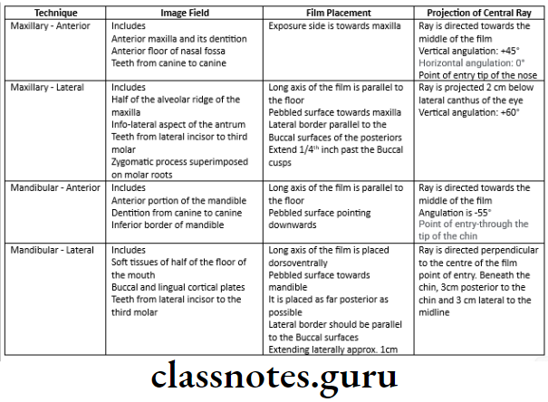
Paranasal lsinuses Techniques:
- Posteroanterior [Granger] projection:
- Structures Seen:
- Inner and middle ear
- Frontal sinuses
- Anterior ethamoidal cells
- Sphenoidal sinus
- Upper part of antrum
- Film Placement:
- Midsagittal plane should be vertical
- It should be perpendicular to the plane of the cassette
- Only forehead and nose should touch the cassette
- Central Ray:
- It is directed to the midline of the skull
- The beam passes through the canthomeatal plane perpendicular to the film plane
Specialized radiographic techniques short essay
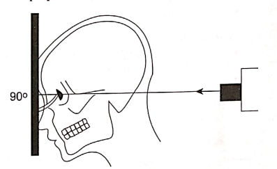
Diagram for the positioning for posteroanterior (Granger) projection
Read And Learn More: Oral Radiology Question and Answers
- Modified method, inclined posterior anterior [Caldwell projection]
- Strucutures Seen:
- Petrous ridges
- Orbits
- Ethamoidal cells
- Film Placement:
- Cassette is placed perpendicular to the floor
- Position of the Patient:
- Mid sagittal plane is perpendicular to the cassette
- Only forehead and nose touches the cassette
- Canthomeatal line is perpendicular to the cassette
- Central Ray:
- Directed 23º to the canthomeatal line
- Enters the skull about 3 cm above the external occipital protuberance and exiting at the glabella
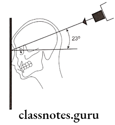
Diagram of the positioning inclined posteroanterior (Caldwell) projection
Short essay on special radiographic procedures
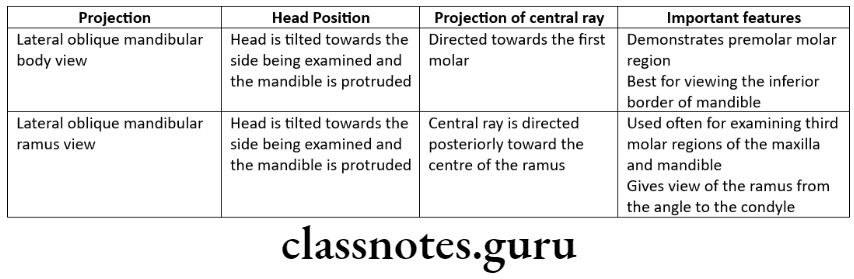
Question 2. Oblique lateral radiograph of mandible.
Answer:
- Anterior body of the mandible:
- Structures Seen:
- Anterior body of mandible
- Position of teeth in that region
- Film Placement:
- Cassette is placed flat against the patient’s cheek
- It is centered over the body of the mandible overlying canine
- Position of the Patient:
- The ala tragus line should be parallel to the floor
- The mandible is protruded slightly
- The inferior borderof the cassette should be parallel to the lower border of the mandible
- The sagittal plane is tilted so that it is 5º to the vertical and rotated 30º from the true lateral position
- The nose and chin should approximate the cassette
- Central Ray:
- Directed from 2 cm below the angle of the mandible opposite to the side of interest
- The beam is directed upward -10º to -15º
- It is centered on the anterior body of the mandible
- The beam is directed perpendicular to the horizontal plane of the film
Short note on specialized radiography
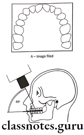
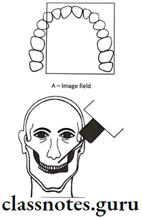
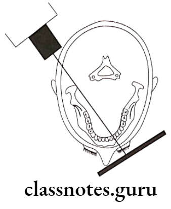
Diagram for the positioning of lateral oblique projection for anterior body of the mandible, film is in contact with the cheek at the canine area, and the X-ray beam aims at the canine area through radiographic key hole
- Posterior Body:
- Structures Seen:
- Body of the mandible
- Position of teeth in that area
- Ramus of the mandible
- Angle of the mandible
- Film Placement:
- The cassette is placed against the patients cheek
- It is centered over the body of the mandible
- The cassette is placed parallel to the body of the mandible
- Position of the Patient:
- The ala tragus line is parallel to the floor
- The mandible is protuded slightly
- The inferior border of the cassette should be parallel to the lower border of the mandible and below it
- The sagittal plane is tilted to 5º to the vertical
- The head is rotated 10º to 15º from the true lateral position
- Central Ray:
- It is directed from 2 cm below the angle of the mandible opposite to the side of interest
- The beam is directed upwards (-10º to -15º)
- It is centered on the body of the mandible
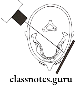
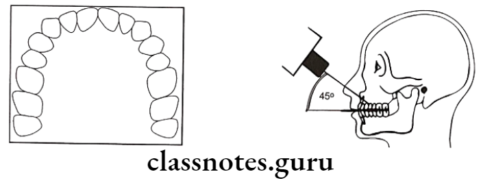
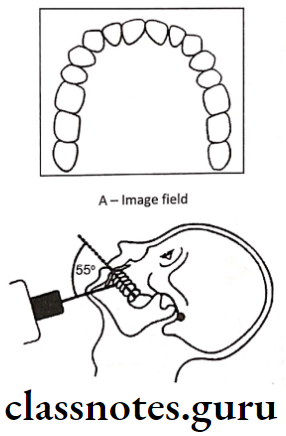
Diagram for the positioning of lateral oblique projection for posterior body of the mandiblem film is in contact with the cheek at the premolar area, and the X-ray beam aims at the premolar area, through the radiographic key hole
- Ramus of Mandible:
- Structures Seen:
- Ramus from the angle of the mandible to the condyles
- Film Placement:
- The cassette is placed against the patients cheek
- It is centered over the ramus of mandible
- It should be parallel to ramus
- Position of the Patient:
- The ala tragus line should be parallel to the floor
- The mandible is protruded slightly
- The inferior border should be parallel to the lower border of the mandible and below it
- The sagittal plane is tilted 10º to the vertical
- The head is rotated 5º from the true lateral
- Central Ray:
- It is directed from 2 cm below the angle of the angle of the mandible opposite to the side of interest to a point posterior to the third molar region
- The beam is directed upwards (-10º to -15º)
- It is centered on the ramus of the mandible
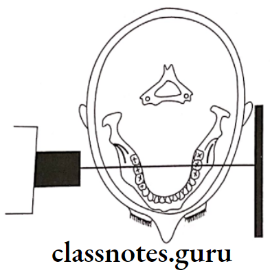
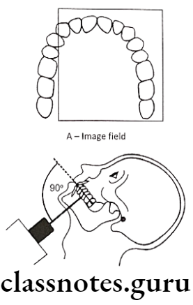
Diagram from the positioning of PA water’s projection, the radiographic baseline is at 37º to the film, and the X-ray is perpendicular to the film
Dental specialized radiographic techniques short answer
Question 3. Water’s projection.
Or
PA Water’s view.
Answer.
Water’s projection
- Structures Seen:
- Maxillary sinus
- Frontal sinus
- Ethamoidal sinus
- Orbit
- Frontozygomatic suture
- Nasal cavity
- Coronoid process
- Zygomatic arch
- Film Placement:
- The cassette is placed perpendicular to the floor
- Position of the Patient:
- The mid sagittal plane should be perpendicular to the plane of the film
- The patient’s head is extended so that only the chin touches the cassette
- The cassette is centered around the acanthion
- The canthomeatal line should be 37º to the plane of the film
- The line from the external auditory meatus to the mental protuberance should be perpendicular to the film
- Central Ray:
- It is directed perpendicular and to the midpoint of the film
- It enters from the vertex and exists from the acanthion
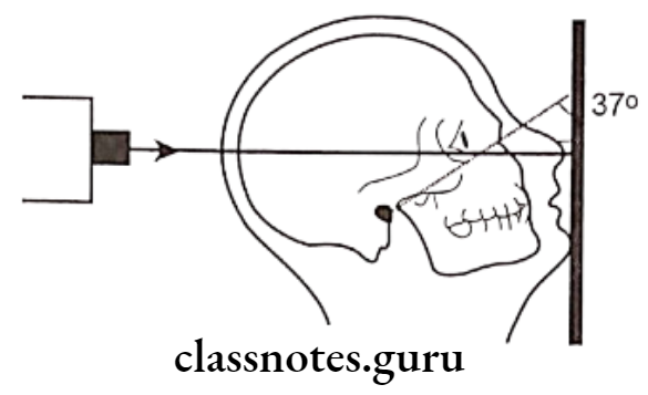
Diagram for the positioning of PA Water’s projection, the radiographic baseline is at 37º to the film, and the X-ray is perpendicular to the film
Short essay on advanced radiographic methods
Question 4. Sialography.
Answer.
Sialography Technique:
- Identification of duct:
- The parotid duct is located at the base of the papilla in the buccal mucosa adjacent to the first or second molar
- The area over the mucosa should be dried with a small sponge
- The submandibular duct orifice is situated on the submitting of the small papilla at the side of the lingual frenum
- Exploring of the duct:
- The duct can be explore with lacrimal probe
- In the case of the submandibular duct, the probe should pass through the length of the floor of the mouth to the level of the posterior border of the mylohyoid muscle i.e. about 5cm
- Eversion of cheek should be done in case of parotid duct
- By it, the duct is adequatly enlarged
- Introduction of cannula:
- The sialographic cannula is inserted into the duct so that the tissue sop presses firmly into the orifice to prevent dye reflux
- Introduce contrasting media:
- Liquid soluble or Water soluble agent is slowly introduced
- Amount of the agent:
- Submandibular glandL 0.5 – 0.75ml
- Parotid gland: 0.76 – 1ml
- Radiograph is taken:
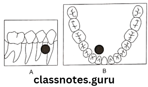
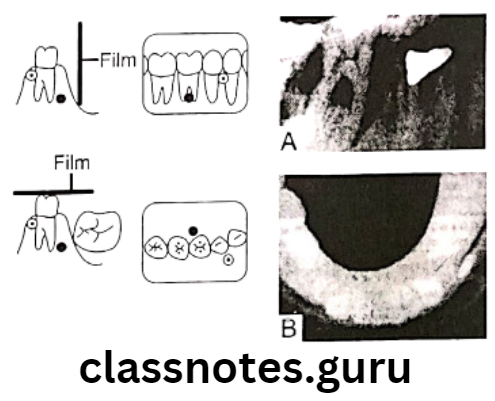
- Occlusal view/lateral oblique view is used to delineate the submandibular gland
- A sialolith is better viewed in occlusal view
- AP view it used for both the glands
- It demonstrates the medial and lateral gland structures
- Evacuation:
- After the radiograph is taken, the cannula should be removed
- The patient is instructed to chew gum or the lemon slice and then asked to rinse
- This is done to stimulate the gland and cause excretion of the dye.
Extraoral radiographic techniques short essay
Question 5. MRI – Principles and indications.
Answer.
MRI – Principles and indications
- It uses nonionizing radiation from the radiofrequency band of the electromagnetic spectrum
MRI Mechanism:
- The patient is placed inside a large magnet
- This induces a strong external magnetic field that causes the nuclei of many atoms in the body including hydrogen to align themselves with the magnetic field
- After application of radiofrequency signal, energy is released from the atoms that can be deteched and used to construct the image by computer
MRI Advantages:
- High sensitivity to detect tissue differences
- No radiation exposure hence no radiation affects the body
- Excellent imaging techniques especially for soft tissues
- It gives the best resolution of tissues of low inherent contrast
MRI Disadvantages:
- Long imaging times
- It gives the potential hazards in a patient with implanted metallic foreign objects like caradiac pacemakers, cerebral aneurysm clips.
- Some patients suffer from claustrophobia when positioned in a MRI machine.
MRI Indications:
- Diagnosing a suspected internal derangement of the TMJ
- Postsurgical evaluation of TMJ
- Identifying and localizing orofacial soft tissue lesions
- Provides the image of salivary gland parenchyma
Intraoral and extraoral specialized imaging short essay
Question 6. Scintigraphy.
Answer.
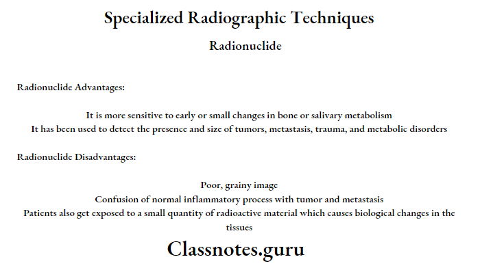
Scintigraphy
- It is based on the radiotracer method
- Radioactive atoms or molecules in organs behave in a manner identical to their counterpart in the body
- The radiotracers allow measurement of tissue function and provide early markers of disease through measurement of biochemical change in tissue before any physical signs and symptoms occur
Method:
- Radioactive substances should be injected innntravenously into the patient
- Rectilinear scanner or gamma scintillation camera records the gamma emission from the patient
- The camera uses a scintillation crystal that can fluorescence on interaction with gamma rays emitting from the radioactive substances
- The emitting light fluorescence is detected by a photomultiplier tube that magnifies and amplifies the signals many times to produce an image
Atom Used:
- Iodine
- Gallium
- Selenium
- Technetium
Scintigraphy Advantages:
- It is more sensitive to early or small changes in bone or salivary metabolism
- It has been used to detect the presence and size of tumors, metastasis, trauma and metabolic disorders
Scintigraphy Disadvantages:
- Poor, grainy image
- Confusion of normal inflammatory process with tumor and metastasis
- Patients also get exposed to a small quantity of radioactive material which causes biological changes in the tissues
Radiographic special procedures short essay
Question 7. Digital radiography.
Answer.
Digital radiography
- The use of digital technology results in a 50 to 90% reduction in patient radiation exposure because of the greater sensitivity of the digital receptor
- Elimination of film processing and no need for dark room
- Considerable reduction in the time lapse between image acquisition and display
Digital radiography Mechanism:
- In digital imaging, the sensor is used i.e., CCD Charged Couple Device instead of radiographic film in the patient’s mouth
- After radiation exposure, the signal from the CCD is sent to the computer where it is digitalized into gray levels
- The image can then be displayed on a monitor, where it can be enhanced by varying the density and contrast
- The image may also be stored for future used
Digital radiography Types:
- Direct digital radiography
- Indirect digital radiography
Digital radiography Advantages:
- Eliminates the X-ray film, thereby reduces the cost of the film
- It serves as a recording, display, and storage for diagnostic images
- It requires less exposure time because of the grater sensitivity of the digit receptor there by preventing the patient from being exposed to radiation
- Eliminates the chemical processing and dark room so that preventing the cause of alllergy and pollution and also considerable reduction in time lapse between image acquisition and display
- Film contrast, density, brightness and color may be manipulated so that image information can be increased
- Reduction in the number of images that need to he remade because of over exposure or under exposure
- Transmission of image to remote sites in a digital format
- Image can be viewed on computer monitor to get an print out on paper
Digital radiography Disadvantages:
- Equipment is expensive
- Trained persons are required
Digital radiography Uses:
- It can be used to view the images where multiple images are required for analyzing
- In endodontic practice to measure the root canal length, working lenght and distance between obturating material and the root apex
- In perioidontics, to assess and measure the height of the alveoplar bone
- It can be used in a patient who is un cooperativge for regular radiographic techiniques
- To evaluate the bony changes in pathology of jaws
- To detect early dental caries
Specialized dental X-ray techniques short note
Question 8. Indications of CT [Computed tomography].
Answer.
Indications of CT [Computed tomography]
- Investigations of intracranial diseases including diseases tumors, hemorrhage and airfacts
- Investigations of suspected intracranial and spinal cord damage following trauma to the head and neck
- Assessment of fractures involving
- Orbits and nasoethamodial complex
- The cranial base
- The odontoid peg
- The cervical spine
- Tumor stagingassessement of site, size and extent of benign and malignant tumors affecting
- The maxillary antra
- The base of the skull
- The pterygoid region
- The pharynx
- The larynx
- Investigations of tumors and tumor like discrete swellings intrinsic and extrinsic to the salivary glands
- Investigation of the TMJ
- Preoperative assessment of maxillary alveolar bone height and thickness before inserting implants
Occlusal radiographic technique short essay
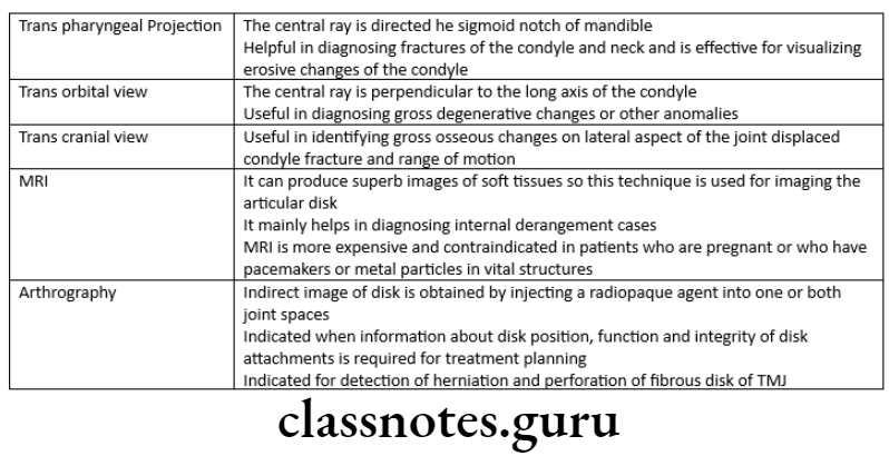
Question 9. Tranpharyngeal view
Answer.
Structures Seen:
- Medial surface of the condylar head and neck
Film Placement:
- The cassette is placed flat against the patient’s ear
- It is centered to a point 1/2″ anterior to the external auditory meatus, over the TMJ of interest
Position of the Patient:
- Sagittal plane should be vertical and parallel to the film
- The film is centered to a point 1/2 “anterior to the external auditory meatus
- The occlusal plane should be parallel to the transverse axis of the film
- The patient should open his mouth
Central Ray:
- It is directed from opposite side cranially at an angle of -5 to -10 degree posteriorly
- It is directed through the Mandibular notch of the opposite side below the base of the skull to the TMJ of interest
Sialography and its radiographic technique
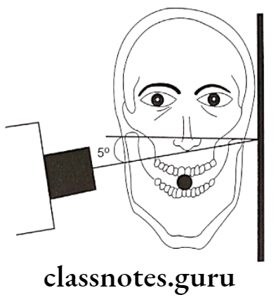
A – Tranpharyngeal projection. The central ray is orient superiorly 5º to 10º and posteriorly approximately 10º, centered over the TMJ of interest. The mandible is positioned at maximal opening
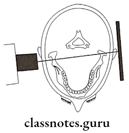
B – Tranpharyngeal projection, showing positioning from above, showing the X-ray beam aimed slightly posteriorly across the pharynx