Development Of Dentition And Occlusion Definitions
- Primate spaces/Simian spaces/Anthropoid spaces
- These are spaces present mesial to the maxillary canines and distal to the mandibular canines
- Incisal liability
- The difference between the amount of space needed for the accommodation of incisors and the amount of space available is called incisal liability.
- Leeway space of Nance
- The differences between the combined mesiodistal width of deciduous canine and molars to the combined mesiodistal width of permanent canine and premolar is called the leeway space of Nance
Development Of Dentition And Occlusion Important Notes
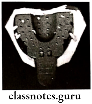
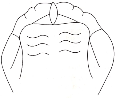
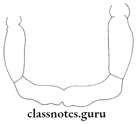
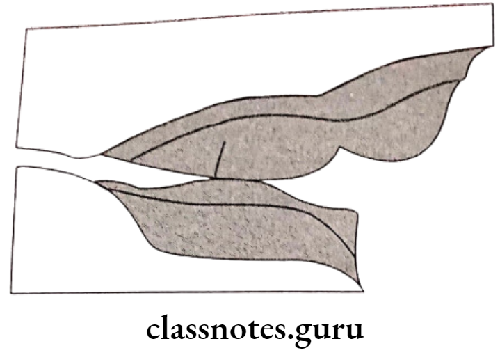
- Gum Pads
- These are alveolar processes present at the time of birth
- They are developed in two parts – labiobuccal and lingual portion
- Both parts are separated by a dental groove
- Gum pads are separated into 10 segments by a transverse groove
- The groove between the canine and first deciduous molar called lateral sulci determines inter arch relationship.
- The shift of lower molars from the flush terminal plane to class 1 occurs by
- Early shift – by utilizing primate spaces
- Late shift – by utilizing leeway space
- Transient maloccusions are
- Open bite in gum pads
- Deep bite
- Spacing in deciduous dentition
- Flush terminal plane
- Ugly duckling stage
- Incisal liability is overcome by
- Utilizing physiologic spaces
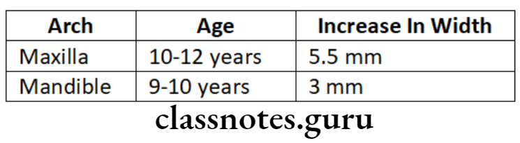
- Increase in inter canine width
- More labial inclination of permanent incisors
- Safety valve mechanism
- An increase in inter-canine width is one of the important factors in overcoming incisal liability
- At the age of 12, maxillary anterior prolines such that inter-canine width increase
- Significance:
- This increase in maxillary intercanine width hinders the forward growth of the mandible
- This increase in width behaves like it holds the forwardly growing mandible
- Maximum intercanine width occurs with the eruption of incisors
- It is more in closed arches than in spaced arches
Read And Learn More: Orthodontics Short And Long Essay Question And Answers
Development Of Dentition And Occlusion Long Essays
Question 1. Describe in detail the developmental periods of occlusion.
Answer.
Periods Of Occlusion Development:
Pre-dental period [after birth upto 6 neonates
Neonats do not have any teeth
- Gum Pads:
- It is the alveolar process at the time of birth
- Pink, firm covered by fibrous periosteum
- Horseshoe shaped
Portions: labio-buccal and lingual – separated by a dental groove
- The transverse groove divides gum pads into 10 segments for 10 deciduous teeth
- Lateral sulcus present between canine and 1st deciduous molar
- Helps for interarch relationship
Upper Gum Pads: Longer and wider
Occlusion: Contact occurs between the upper and lower gum pads at the region of the first molar only. This facilitates sucking.
- Status of Dentition:
- Usually, no teeth are present at birth
- Teeth present at the time of birth – Natal teeth
- Teeth present during 1st month of age – Neonatal
- Both are located in mandibular incisor regions
Deciduous dentition period:
- Period – 6 months – 2 1/2 – 3 1/2 years
- The sequence of eruption – A – B – D – C – E
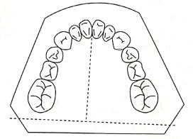
- SPACING – [Called Physiological spaces]
- Present mesial to maxillary canine and distal to mandibular canine
- Common in primates
Significance Of Periods Of Occlusion:
- Helps in the placement of canine cusps of the opposite arch
- Its absence leads to crowding
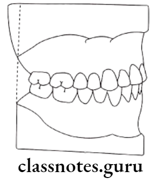
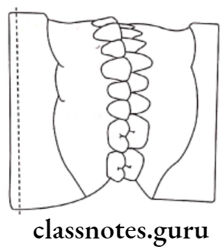
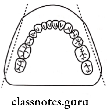
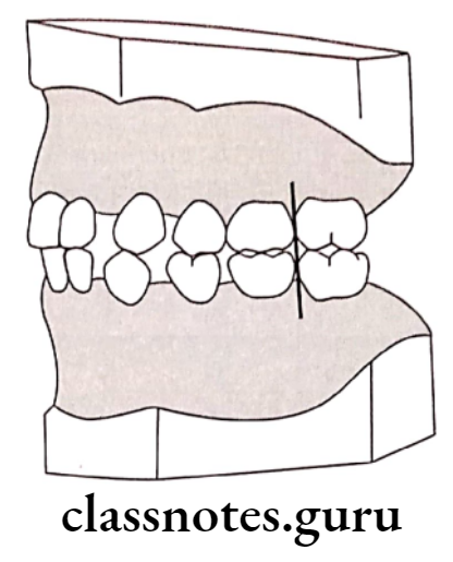
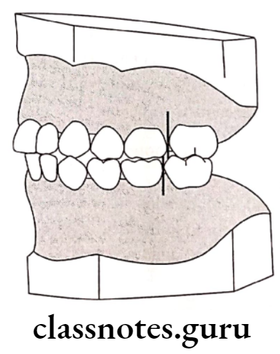
- Flush Terminal Plane:
- Mesio-distal relation between the distal surfaces of upper and lower second deciduous molars is called the terminal plane
- It lies in the same vertical plane
- Deep bite:
- Due to the presence of more upright deciduous incisors
- It overcomes by the following
- Forward growth of the mandible
- Attrition of incisors
- Eruption of deciduous molars
Mixed dentition period:
- Age: 6 years of age
- Consists of: Both deciduous and permanent teeth
Phases:
First Transitional period:
- Emergence of first permanent molar:
- At the age of 6 years
- Its location depends upon the flush terminal plane
- Flush Terminal Plane:
- Digital surfaces of upper and lower 2nd deciduous molars lie in the same vertical plane
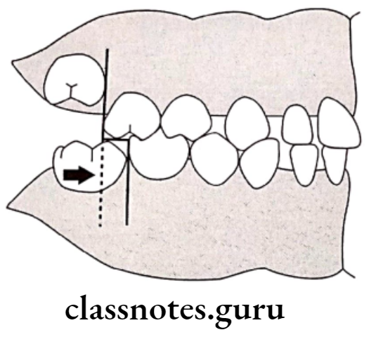
- Erupting 1st permanent molar forms end in relation
- This is transferred to class 1 relation by the movement of the lower molar by 3-5 mm
- Utilization of physiological spaces and leeway spaces
- At the early stage of life By utilization of leeway space late shift
- By utilization of physiological spaces
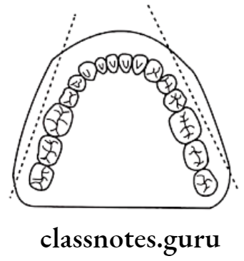
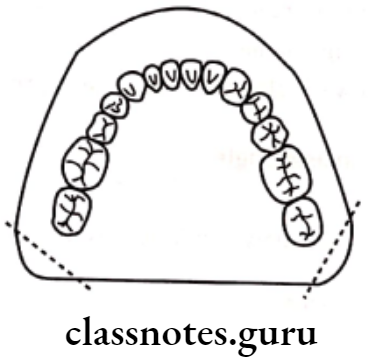
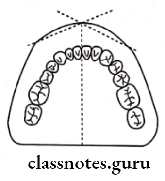
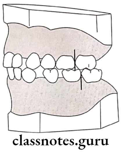
- Mesial Step terminal plane:
- Here the distal surface of the lower deciduous 2nd molar is located mesial to that of the upper 2nd deciduous molar
- Eruption of permanent molar occurs in class 1 relation
- If further mandibular growth occurs, it leads to class 3 relation
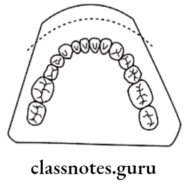
- Distal step terminal plane:
- The distal surface of the lower deciduous 2ndmolar is located distal to that of the upper deciduous 2nd molar
- Eruption of permanent molar occurs in class 2 relation
Exchange of incisors:
- Exchange of deciduous incisors by permanent incisors
- Difference between the amount of space needed for accumulating permanent incisors and the amount of space that exists occurs
- This is called Incisor liability
- Maxilla – 7mm
- Mandible – 5mm
- Incisor liability is overcome by
- Utilization of interdental spaces
- Increase in inter-canine width
- Change in incisor inclination
- Inter transitional period:
- Consists of
- Permanent incisors
- Permanent first molars
- Canines and deciduous molars
- Consists of
Second transitional period:
- It is the replacement of deciduous canines and molars by their permanent successors
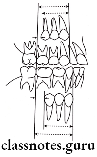
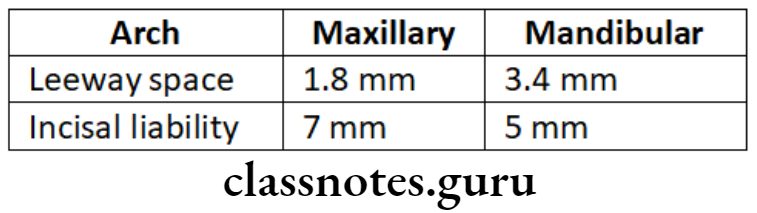
Leeway space of Nance:
- The combined mesiodistal width of premolars and permanent canine is less than that of deciduous molars and canines
- This is called the Leeway space of Nance.
- Value: Maxillary arch – 1.8mm
- Mandibular arch – 3.4mm
Significance Of Leeway Space of Nance:
- Utilization of this space during the late shift
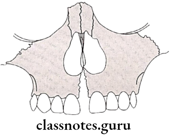
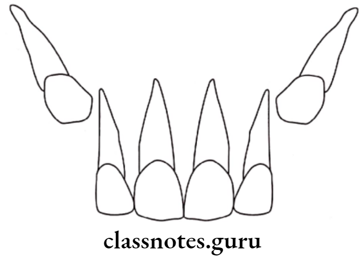
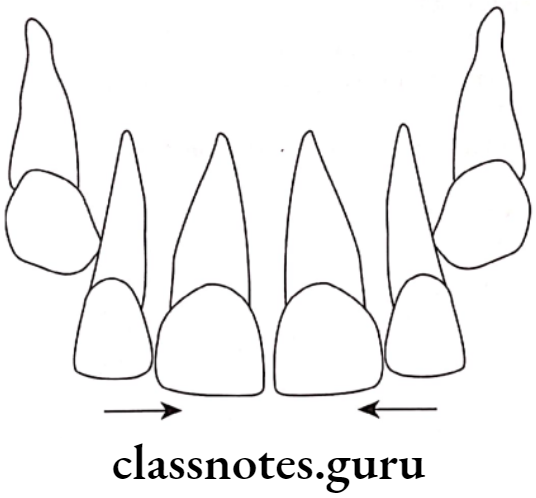
Ugly Duckling Stage:
- Described by Broadbent
- Age – 8-9 years
- At the time of the eruption of canines
Stage Feature:
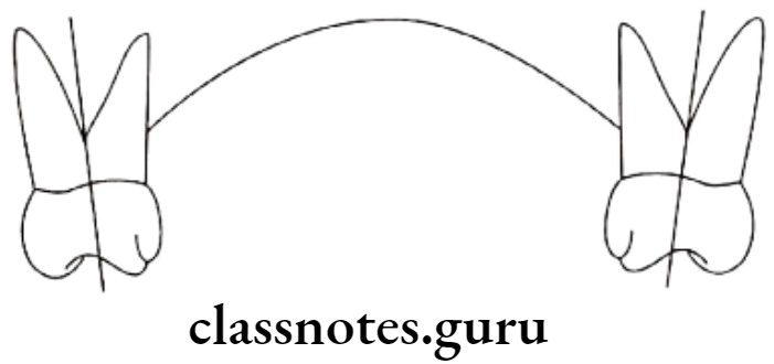
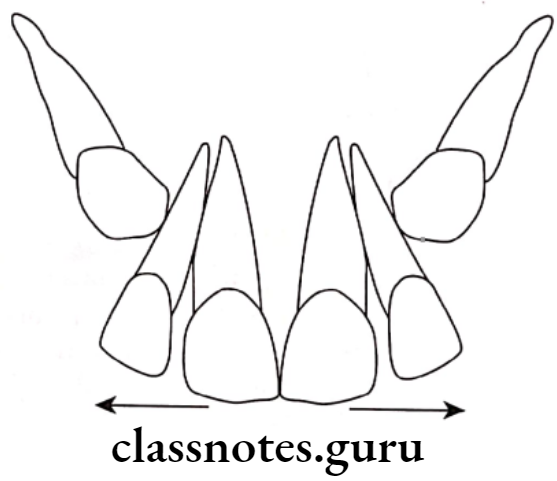
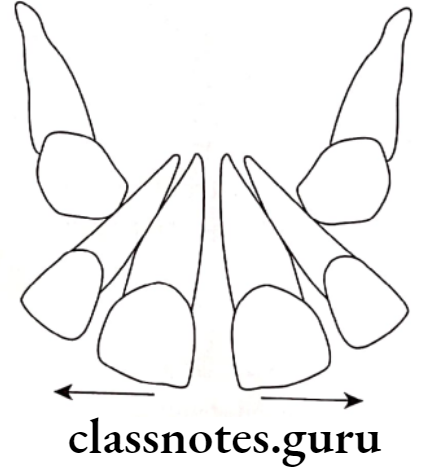
- As the permanent canine erupts, it pushes the root of the lateral incisor in turn pushes the root of the central incisor
Result Of Ugly Duckling Stage:
- Mesially displaced roots of incisors
- Distally displaced crowns of incisors
- Results in mid-line spacing
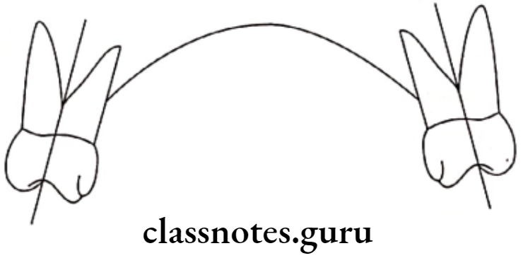
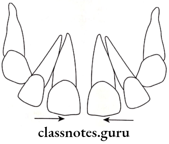
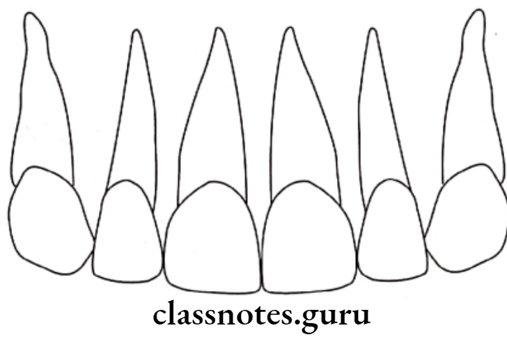
Significance Of Ugly Duckling Stage:
- It is a a self-correcting anomaly
- Corrected by the completion of the eruption of permanent canine
- Due to the transfer of force from the roots to the crowns
Permanent dentition period:
- Eruption sequence for both the arches
6-1-2-4-3-5-7 or 6-1-2-3-4-5-7
Question 2. What are the stages of development of dentition? Write in detail about the self-correcting malocclusion
Answer.
Stages Of Development Of Dentition:
Pre-dental period [after birth upto 6 months]:
Neonates do not have any teeth
- Gum Pads:
- It is the alveolar process at the time of birth
- Pink, firm covered by fibrous periosteum
- Horseshoe shaped
- Status of Dentition:
- Usually, no teeth are present at birth
Deciduous dentition period:
- Period – 6 months – 2 1/2 – 3 1/2 years
Mixed dentition period:
- Age: 6 years of age
- Consists of: Both deciduous and permanent teeth
Phases:
First Transitional period:
- Emergence of first permanent molar:
- At the age of 6 years
- Its location depends upon the flush terminal plane
- Exchange of incisors:
- Exchange of deciduous incisors by permanent incisors
Inter transitional period:
- Consists of
- Permanent incisors
- Permanent first molars
- Canines and deciduous molars
- Stable period
Second transitional period:
- It is the replacement of deciduous canines and molars by their permanent successors
Permanent dentition period:
- Eruption sequence for both the arches
6-1-2-4-3-5-7 or 6-1-2-3-4-5-7
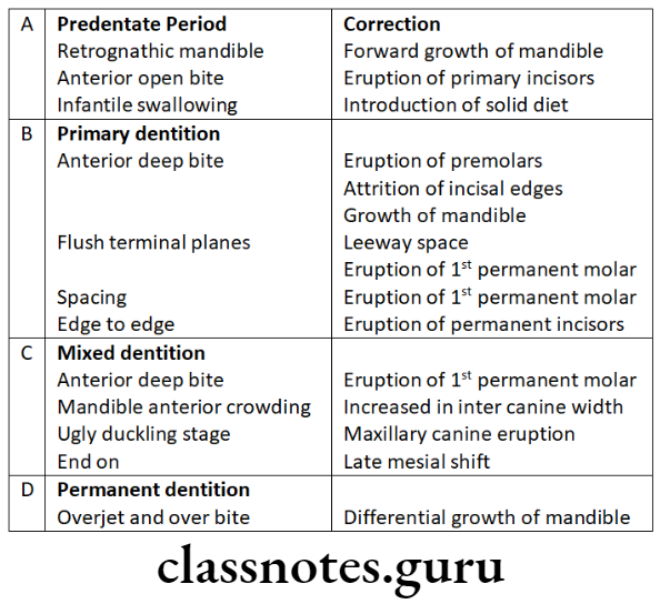
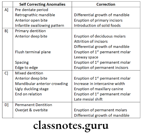
Self-correcting malocclusion:
Development Of Dentition And Occlusion Short Essays
Question 1. Gum Pads.
Answer.
- It is the alveolar process at the time of birth
- Pink, firm covered by fibrous periosteum
- Horseshoe shaped
Portions Of Gum Pads:
- Labio-buccal and lingual – separated by a dental groove
- The transverse groove divides gum pads into 10 segments for 10 deciduous teeth
- Lateral sulcus present between canine and 1st deciduous molar
- Helps for interarch relationship
Upper Gum Pads:
- Longer and wider
Occlusion:
- Contact occurs between the upper and lower gum pads at the region of the first molar only. This facilitates sucking.
Question 2. Self Correcting anomalies
Answer.
Question 3. Broadbent phenomenon.
Answer.
- The ugly duckling stage was described by Broadbent
- Thus it is known as the Broadbent phenomenon
Ugly Duckling Stage:
- Described by Broadbent
- Age – 8-9 years
- At the time of the eruption of canines
Stage Feature:
- As the permanent canine erupts, it pushes the root of lateral incisors this in turn pushes the root of the central incisor
Result Of Ugly Duckling Stage:
- Mesially displaced roots of incisors
- Disatally displaced crowns of incisors
- Results in mid-line spacing
Significance Of Ugly Duckling Stage:
- It is a self-correcting anomaly
- Corrected by the completion of the eruption of permanent canine
- Due to the transfer of force from the roots to the crowns
Development Of Dentition And Occlusion Short Questions And Answers
Question 1. Physiological spacing.
Answer.
- Present mesial to maxillary canine and distal to mandibular canine
- Common in primates
Significance Of Physiological Spacing:
- Helps in the placement of canine cusps of the opposite arch
- Its absence leads to crowding
Question 2. Incisal liability.
Answer.
- Difference between the amount of space needed for accumulating permanent incisors and the amount of space that exists occurs
- This is called Incisor liability
- Maxilla – 7mm
- Mandible – 5mm
- Incisor liability is overcome by
- Utilization of interdental spaces
- Increase in inter-canine width
- Change in incisor inclination
Question 3. Leeway space of Nance.
Answer.
- The combined mesiodistal width of premolars and permanent canine is less than that of deciduous molars and canines
- This is called the Leeway space of Nance.
- Value: Maxillary arch – 1.8mm
- Mandibular arch – 3.4mm
- Significance Of Leeway Space of Nance: Utilization of this space during the late shift
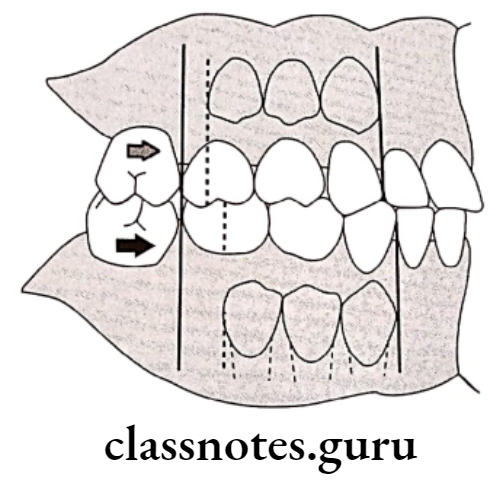
Question 4. Late mesial shift.
Answer.
- Many children lack physiological spaces
- Thus erupting permanent molars are unable to move forward to establish a Class 1 relationship
- In these cases, when the deciduous second molars exfoliate the permanent first mol. ars drift mesially utilizing the leeway space
- This occurs in the late mixed dentition period
- Thus it is called late shift
Question 5. Enumerate the stages of tooth development.
Answer.
- The development of tooth was divided into 10 stages by Nolla as follows
- Stage 1 – Presence of crypt
- Stage 2 – Initial calcification
- Stage 3 – One-third of crown completion
- Stage 4 – Two-thirds of crown completion
- Stage 5 – Crown almost completed
- Stage 6 – Crown completed
- Stage 7 – One-third of the root completed
- Stage 8 – Two-thirds of the root completed
- Stage 9 – Root almost completed with open apex
- Stage 10 – Apical end of the root completed
Development Of Dentition And Occlusion Viva Voce
- The stages of tooth development are the bud cap and bell stage.
- Lateral sulci present between canine and deciduous first molar determine interact relation
- The mixed dentition period can be classified into 3 phases – first transitional, transitional, and second transitional.
- The first transitional period is characterized by the emergence of the first permanent molars and the exchange of deciduous incisors with permanent incisors
- Inter transitional period is relatively stable and no change occurs
- The second transitional period is characterized by the replacement of deciduous molars and canines by premolar and permanent canines
- Primate spaces help in the placement of canine cusps on the opposing arch
- Values
- Ugly duckling stage is transient malocclusion
- Primate spaces are utilized during the early medial shift of molars
- Initiation of primary dentition occurs in 6 weeks of IU life
- Broadbent coined the term ugly duckling stage
- Mandibular central incisors are the first tooth to erupt in primary dentition
- Nance determined the leeway space
- The ugly duckling stage is seen between 8-9 years