Specialized Radiographic Techniques Long Essays

Specialized Radiographic Techniques Long Essays

Question 1. Enumerate techniques for TMJ imaging. Describe any two in detail.
Answer.

Techniques For TMJ Imaging:

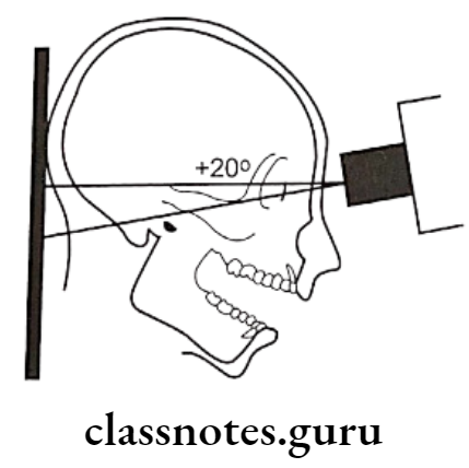
  • Transcranial projection:
    • Structure Seen:
      • Useful in detecting arthritis of the articular surfaces
      • To evaluate the joint’s bony relationship
    • Film Position:
      • The cassette is placed against the patient’s ear and centered over the TMJ of interest
      • It is placed parallel to the sagittal plane
    • Patient’s Position:
      • The sagittal plane must be vertical
      • The ala tragus line should be parallel to the floor
      • The view is taken with
        • Open mouth
        • Rest position
        • Closed mouth
    • Central Ray:
      • It differs according to the technique
      • Postauricular
        • Point of entry is 1/2 “behind and 2” above the auditory meatus
      • Grewcock approach
        • The path of entry is through point 2 above the auditory meatus
      • Gill’s approach
        • Point of entry is 1/2 “anterior and 2” above the auditory meatus
    • Angulation: +20º To +25º
    • Point Of Exit: TMJ of interest

Oral Radiology Specialized Radiographic Techniques Transcranial projection 1

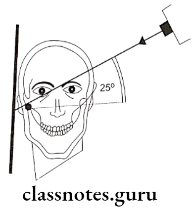
A – Transcranial projection, the central ray is oriented at 25º positive angle from the opposite side and anteriorly 20º, centered over the TMJ of interest, mouth closed

Oral Radiology Specialized Radiographic Techniques Transcranial projection 2

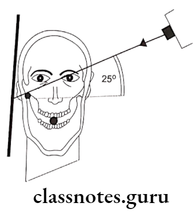
B – Transcranial projection, the central ray is oriented at 25º positive angle from the opposite side and anteriorly 20º, centered over the TMJ of interest, mouth open

  • Tranpharyngeal projection:
    • Structures Seen:
      • The medial surface of the condylar head and neck
    • Film Placement:
      • The cassette is placed flat against the patient’s ear
      • It is centered to a point 1/2″ anterior to the external auditory meatus, over the TMJ of interest

Read And Learn More: Oral Radiology Question and Answers

    • Position of the Patient:
      • The sagittal plane should be vertical and parallel to the film
      • The film is centered to a point 1/2 “anterior to the external auditory meatus
      • The occlusal plane should be parallel to the transverse axis of the film
      • The patient should open his mouth
    • Central Ray:
      • It is directed from the opposite side cranially at an angle of -5 to -10 degrees posteriorly
      • It is directed through the Mandibular notch of the opposite side below the base of the skull to the TMJ of interest

Oral Radiology Specialized Radiographic Techniques Transpharyngeal projection 1

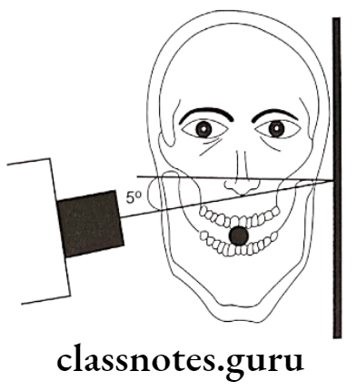
A – Transpharyngeal projection. The central ray is oriented superiorly 5º to 10º and posteriorly approximately 10º, centered over the TMJ of interest. The mandible is positioned at the maximal opening

Oral Radiology Specialized Radiographic Techniques Transpharyngeal projection 2

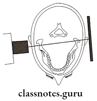
B – Transpharyngeal projection, showing positioning from above, showing the X-ray beam aimed slightly posteriorly across the pharynx

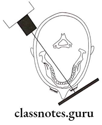
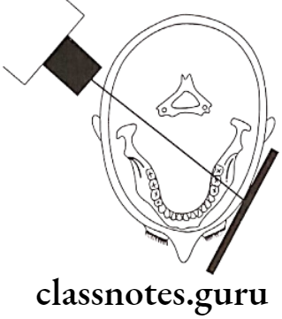
  • Transorbital Projection:
    • Structures Seen:
      • The anterior view of TMJ
    • Film Placement:
      • The film is positioned behind the patient’s head at an angle of 45 degrees to the sagittal plane
    • Position of the Patient:
      • The Sagittal Plane should be vertical
      • The canthomeatal line should be 10 degrees to the horizontal
      • Head tipped downwards
      • The mouth should be widely open
    • Central Ray:
      • Directed to the joint of interest at an angle of +20 degree
      • Strike the cassette at a right angle
        • Point of entry
        • A pupil of the same eye
        • Medial canthus of the same eye
        • Medial canthus of the opposite eye

Oral Radiology Specialized Radiographic Techniques Transorbital projection 1

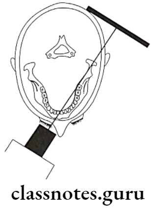
A – Transorbital projection, the central ray is oriented downward approximately 20º and laterally approximately 30º through the contralateral orbit, centered over the TMJ of interest

Oral Radiology Specialized Radiographic Techniques Transorbital projection 2

B – Transorbital projection, positioning from above, showing the cassette behind the condyletown’sray beam aimed across the orbit

  • Reverse towne’s projection:
    • Structures Seen:
      • Condylar head and neck
    • Film placement:
      • The cassette is placed perpendicular to the floor
    • Position of the Patient:
      • The sagittal plane should be vertical and perpendicular to the film
      • Lips should be centered on the film
      • Only the patient’s forehead should touch the film
      • The patient is asked to keep his mouth wide open
      • Angulation is -30º to the film
    • Central Ray:
      • It is directed through the midsagittal plane at the level of the mandible
      • It is perpendicular to the film

Oral Radiology Specialized Radiographic Techniques Diagram for the positioning of Reverse Townes projection

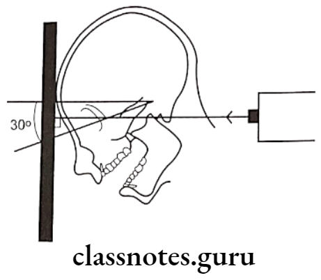
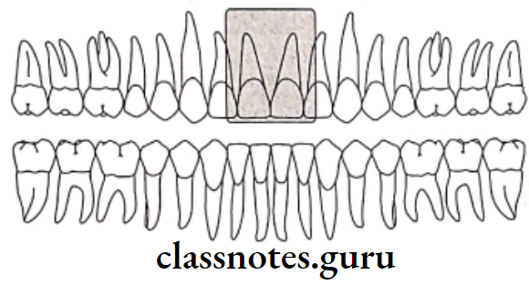
Diagram for the positioning of Reverse Towne’s projection, the radiographic baseline is 30º to the film and the X-ray is directed perpendicular to the film

Question 2. Describe sialography in detail.
Or
Describe indications, contraindications, and technique of sialography.
Or
Describe sialography and write on its signs in various salivary gland disorders.
Answer.

Sialography Indications:

  • Detection of calculus or foreign bodies
  • Determination of the extent of destruction of the gland secondary to obstructing calculi or foreign bodies
  • Detection of fistula, diverticula, or strictures
  • Determination and diagnosis of recurrent swellings and inflammatory processes
  • Demonstration of a tumor and the determination of its location, size, and origin
  • Selection of a site for biopsy
  • Outline of the plane of the facial nerve
  • Detection of residual stones
  • Sialography can be used for therapeutic procedures

Sialography  Contradictations:

  • Patients with knowacutesitivity of iodine
  • During the presence of avute inflammation
  • It may interfere with subsequent thyroid function tests

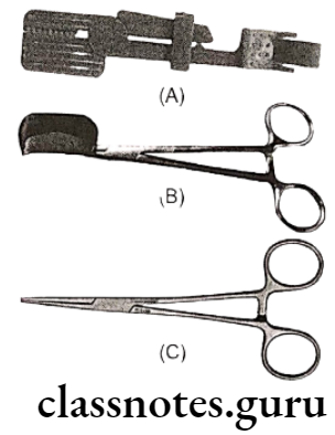
Sialography  Technique:

  • Identification of duct:
    • The parotid duct is located at the base of the papilla in the buccal mucosa adjacent to the first or second molar
    • The area over the mucosa should be dried with a small sponge
    • The submandibular duct orifice is situated on the summit of the small papilla at the side of the lingual frenum
  • Exploring of the duct:
    • The duct can be explored with a lacrimal probe
    • In the case of the submandibular duct, the probe should pass through the length of the floor of the mouth to the level of the posterior border of the mylohyoid muscle i.e. about 5cm
    • Eversion of the cheek should be done in case of parotid duct
    • By it, the duct is adequately enlarged
  • Introduction of cannula:
    • The sialographic cannula is inserted into the duct so that the tissue stop presses firmly into the orifice to prevent dye reflux
  • Introduce contrasting media:
    • Liquid-soluble or water-soluble agents are slowly introduced
  • Amount of the agent:
    • Submandibular gland: 0.5 – 0.75 ml
    • Parotid gland 0.76 – 1ml
  • Radiograph is taken:
    • Occlusal view/ lateral oblique view is sialolith delineate the submandibular gland
    • view itith is better viewed in an occlusal view
    • AP viewit is used for both the glands
    • It demonstrates the medial and lateral gland structures
  • Evacuation:
    • After the radiography is taken, the cannula should be removed
    • The patient is instructed to chew gum or the lemon slice and then asked to rinse
    • This is done to stimulate the gland and cause excretion of the dye

Radiographic Appearance In Different Disorders:

  • Parotid Gland – tree in winter appearance
  • Submandibular gland – Bush in winter appearance
  • Sjogren’s syndrome – Cherry blossom appearance
    • Results in thinning of individual ducts and decrease in number of ducts
  • Malignant tumor – Ball holding in hand appearance
  • Stones within duct
  • Results in filling defect distal to the site of obstruction
  • There can be dilatation of the duct proximal to the obstruction

Question 3. Enumerate various radiographic techniques for the diagnosis of fracture of the mandible.
Answer.

Radiographic Techniques For Diagnosis Of Fracture Of Mandible:

  • Orthopantomogram:
    • It is a technique for producing a single tomographic image of the facial structures that induce both the maxillary and mandible dental arches and their supporting structures
    • Principle:
      • This is based on the curvilinear variant of conventional tomography
      • The movement of the tube head and the film produces images through the process known as tomography
      • Curvilinear tomography is also based on the principle of reciprocal movement of an X-ray source and an image receptor around a central point or plane called an image layer
    • Procedure:
      • Explain the procedure to the patient
      • Make the patient remove all the accessories that may interfere with the image
      • Position the patient such that he is in the focal trough
      • Instruct the patient to look straight
      • The patient is positioned such that dental arches are located in the middle of the focal trough
      • Mid sagittal plane is kept perpendicular to the floor
      • The patient back and spine are adjusted in an erect position
      • The occlusal plane is adjusted such that the Frankfort plane is parallel to the floor
      • This is done by placing the central incisor into a notched incisal device with a lead marker
      • Center the lower border of the mandible on the chin rest and is equidistant
      • Instruct the patient to position the tongue on the palate
      • Exposure the film
      • Process it as usual
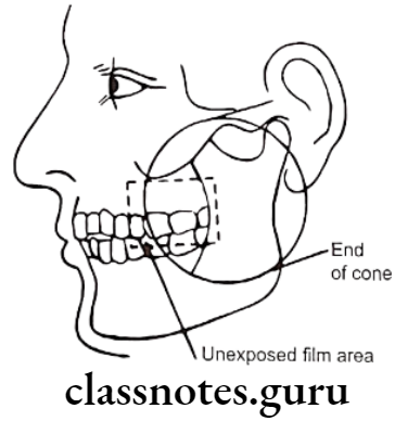
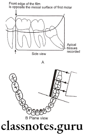
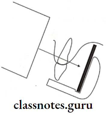
  • Lateral oblique view:
    • Anterior body of the mandible:
      • Structures Seen:
        • Anterior body of mandible
        • Position of teeth in that region
      • Film Placement:
        • The cassette is placed flat against the patient’s cheek
        • It is centered over the body of the mandible overlying the canine
      • Position of the Patient:
        • The ala tragus line should be parallel to the floor
        • The mandible iscassetteded slightly
        • The inferior border of the casette should be parallel to the lower border of the mandible
        • The sagittal plane is tilted so that it is 5º to the vertical and rotated 30º from the true lateral poscassettehe nose and chin should approximate the casette
      • Central Ray:
        • Directed from 2 cm below the angle of the mandible opposite to the side of interest
        • The beam is directed upward from -10º to -15º
        • It is centered on the anterior body of the mandible
        • The beam is directed perpendicular to the horizontal plane of the film

Oral Radiology Specialized Radiographic Techniques Diagram for the positioning of lateral oblique projection 1

Diagram for the positioning of lateral oblique projection for the anterior body of the mandible, the film is in contact with the cheek at the canine area, and the X-ray beam aims at the canine area, through the radiographic keyhole
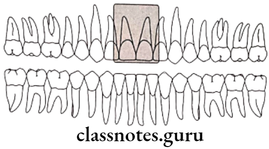
    • Posterior Body:
      • Structures Seen:
        • Body of the mandible
        • Position of teeth in that area
        • Ramus of the mandible
        • The angle of the mandible
      • Film Placement:
        • The cassette is placed against the patient’s cheek
        • It is centered over the body of the mandible
        • The cassette is placed parallel to the body of the mandible
      • Position of the Patient:
        • The ala tragusprotruded parallel to the floor
        • The mandible is protuded slightly
        • The inferior border of the cassette should be parallel to the lower border of the mandible and below it
        • The sagittal plane is tilted to 5º to the vertical
        • The head is rotated 10º to 15º from the true lateral position
      • Central Ray:
        • It is directed from 2 cm below the angle of the mandible opposite to the side of interest
        • The beam is directed upwards (-10º to -15º)
        • It is centered on the body of the mandible

Oral Radiology Specialized Radiographic Techniques Diagram for the positioning of lateral oblique projection 2

The diagram for the positioning of lateral oblique projection for the posterior body of the mandible film is in contact with the cheek at the premolar area, and the X-ray beam aims at the premolar area, through the radiographic keyhole
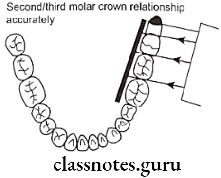
  • Ramus of Mandible:
    • Structures Seen:
      • Ramus from the angle of the mandible to the condyles
    • Film Placement:
        • The cassette is placed against the patient’s cheek
      • It is centered over the ramus of the mandible
      • It should be parallel to the ramus
    • Position of the Patient:
      • The ala tragus line should be parallel to the floor
      • The mandible protrudes slightly
      • The inferior border should be parallel to the lower border of the mandible and below it
      • The sagittal plane is tilted 10º to the vertical
      • The head is rotated 5º from the true lateral
    • Central Ray:
      • It is directed from 2 cm below the angle of the angle of the mandible opposite to the side of interest to a point posterior to the third molar region
      • The beam is directed upwards (-10º to -15º)
      • It is centered on the ramus of the mandible
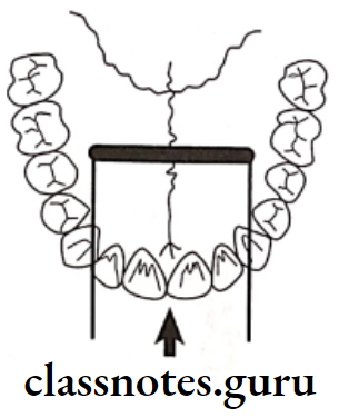
  • Posteroanterior or anteroposterior view:
    • Film Placement:
      • The cassette is placed perpendicular to the floor
    • Position of the Patient:
      • The mid-sagittal plane should be perpendicular to the plane of the film
      • The patient’s head is extended so that only the chin touches the cassette
      • The cassette is centered around the acanthion
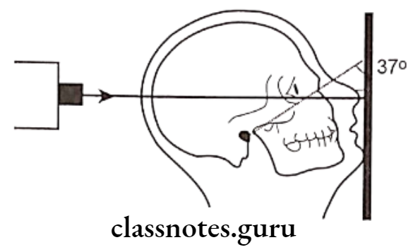
      • The canthomeatal line should be 37º to the plane of the film
      • The line from the external auditory meatus to the mental protuberance should be perpendicular to the film
    • Central Ray:
      • It is directed perpendicular and to the midpoint of the film
      • It enters from the vertex and exists from the acanthion

Oral Radiology Specialized Radiographic Techniques Diagram for the positioning of PA Water projection

Diagram for the positioning of PA water’s projection, the radiographic baseline is at 37º to the film, and the X-ray is perpendicular to the film

  • Reverse Towne view:
    • Film Placement:
      • The cassette is placed perpendicular to the floor
    • Position of the Patient:
      • The sagittal plane should be vertical and peronndicular to the film
      • Lips should be centered to the film
      • Only the patient’s forehead should touch the film
      • The patient is asked to keep his mouth wide open
      • Angulation is -30º to the film
    • Central Ray:
      • It is directed through the midsagittal plane at the level of the mandible
      • It is perpendicular to the film

Oral Radiology Specialized Radiographic Techniques Diagram for the positioning of Reverse Townes projection

Diagram for the positioning of Reverse Towne’s projection, the radiographic baseline is 30ºto the film, and the X-ray is directed perpendicular to the film

Intraoral Radiographic Techniques Long Essays

Intraoral Radiographic Techniques Important Notes

Intraoral Radiographic Techniques

  • Paralleling Technique:
    • Also called as right angle or long cone technique
    • The film is placed parallel to the long axis of the teeth (object).
    • The central ray is perpendicular to both the object and the film.
    • This technique minimizes distortion, as it obeys the imaging principles.
    • The paralleling technique is the preferred method of taking IOPA
      Disadvantages

      • To position the film parallel to the teeth, the film should be placed away from the teeth making it difficult to hold without the use of film holders.
      • The increased object film distance can result in some image magnification and loss of definition by increasing the penumbra.
  • Bisecting Angle Technique:
    • It is based on CIEZYNSKI’s rule of isometry
    • The film is placed closer to the teeth and is not parallel to the long axis of the teeth.
    • The central ray is perpendicular to the imaginary plane that bisects the angle formed by the film with the axis of the object
    • This arrangement inherently causes some distortion.
  • Angulations for bisecting angle technique:

Oral Radiology Intraoral Radiographic Techniques Angulations for bisecting angle technique

  • Vertical angulations for child patients:

Oral Radiology Intraoral Radiographic Techniques Vertical angulations for child patient

  • The number of radiographs required according to age is

Oral Radiology Intraoral Radiographic Techniques The number of radiographs required according to age

Intraoral Radiographic Techniques Long Essays

Question 1. Compare short-cone and long-cone techniques. Describe the technique of radiography of the lower third molar.
Answer.

Comparison of short-cone and long-cone techniques

Oral Radiology Intraoral Radiographic Techniques Short and Long Cone Technique

Oral Radiology Intraoral Radiographic Techniques Diagram showing vertical angulations of bisecting angle

Read And Learn More: Oral Radiology Question and Answers

Oral Radiology Intraoral Radiographic Techniques Vertical X ray beam directions

Oral Radiology Intraoral Radiographic Techniques Shallow palate vault

Oral Radiology Intraoral Radiographic Techniques Cone cutting of the mesial portion

Bisecting Angle Technique:

  • The main difficulty is the placement of the film packet sufficiently posteriorly to record the entire third Mandibular molar and surrounding tissues, including the inferior dental canal
  • The possible solutions are
    • Using a surgical needle holder to hold and position the film packet in the mouth as follows
    • The film holder is clipped securely on the top edge of the film packet
    • With the mouth open, the film packet is positioned gently in the lingual sulcus as far posteriorly as possible
    • The patient is asked to close the mouth on the handles and at the same time the film packet is eased further back into the mouth
    • The patient is asked to support the handles of the needle holder in position
    • The X-ray tube is positioned at right angles to the third molar and the film packet
    • It is centered 1 cm above the lower border of the mandible on a vertical line dropped from the outer canthus of the eye

Oral Radiology Intraoral Radiographic Techniques Diagram showing ideal film packet position

Oral Radiology Intraoral Radiographic Techniques A selection of film packet holders for mandibular third molars

  • Taking two radiographs of the third molar using two different horizontal tube head angulations
  • The film packet is positioned as posteriorly as possible
  • The X-ray tube is aimed at ideal horizontal angulations
  • A second film packet is placed in the same position, but the X-ray tube is positioned further posteriorly to project the apex of the third molar onto the film
  • The vertical angulations are the same for both projections

Oral Radiology Intraoral Radiographic Techniques Plane view showing X ray tube head position 1

Image Field:

  • The projection should show the three molars

Film Placement:

  • The film should be placed with the inferior border positioned beneath the lateral border of the tongue and against the lingual surface of the mandible
  • The superior border should be just above the cusps of the Mandibular molars
  • The anterior border should cover the mesial half of the first molar

Projection Of Central Ray:

  • It Should pass through the interproximal space between the molar teeth
  • The point of entry is on the cheek below, a little posterior to the lateral canthus of the eye, approximately 3cm above the inferior border of the mandible
  • The central ray is angled perpendicular to the bisector through the middle of the canine with a vertical angulation of about -5 to -10 degrees

Oral Radiology Intraoral Radiographic Techniques A Image field The projection should show the three mandibular molars

Oral Radiology Intraoral Radiographic Techniques Film should be placed with the inferior border

Oral Radiology Intraoral Radiographic Techniques C projection of central ray

Oral Radiology Intraoral Radiographic Techniques D Radiograph of mandibular third molar

Question 2. Describe in detail about bisecting angle technique.
Or
Write a note on the principles of imaging. Describe the bisecting angle technique.
Answer.

Principle Of Imaging

  • The focal spot should be as small as possible
  • The focal spot-object distance should be as long as possible
  • The object-film distance should be as small as possible
  • The long axis of the object and the film planes should be parallel
  • The X-ray beam should strike the object and the film planes at right angles
  • There should be no movement of the tube, film, or patient during exposure

Bisecting Angle Technique:

  • It is also called Short Cone Technique
  • It is based on the principle known as “Ciesenzky’s rule of isometry”
  • It states that the two triangles at equal if they have two equal angles and share a common side
  • The X-ray beam should bisect the imaginary bisector that bisects the angle formed by the film and the long axis of the tooth
  • When the rule is strictly followed, the resultant image obtained is accurate

Oral Radiology Intraoral Radiographic Techniques Angle A is bisected by line AC

Oral Radiology Intraoral Radiographic Techniques The image on the film is equal to the length of the tooth

Film Stabilization:

  • The film-holding devices or the patient’s finger is used to position and stabilize the film
  • The patient’s finger or thumb is used
  • It is always placed behind the film and teeth
  • The patient’s thumb is used to position maxillary films
  • While index finger to stabilize Mandibular films
  • The patient’s left hand is used for exposure on the right side of the mouth
  • Right hand for exposure on the left side of the mouth

Guidelines:

  • The white side of the film always faces the teeth
  • Anterior films are always placed vertically
  • Posterior films are always placed horizontally
  • The incisal or occlusal edge of the film must extend approximately 1/8th inch beyond the incisal or occlusal surface of the tooth
  • Always center the film over the area to be examined
  • If the patient’s finger is used for stabilization, instruct the patient to gently push the film against the lingual/palatal surface of the tooth

Patient’s Position:

  • Explain the procedure to the patient
  • Position the patient comfortably on the chair
  • Adjust the patient such that the arch being examined is parallel to the floor and the mid-sagittal plane is perpendicular to the floor
  • Place and secure the lead aprons and thyroid collars
  • Remove the accessories that may interfere with the exposure

Angulations:

  • Horizontal angulation is achieved by directing the central ray perpendicular to the curvature of the arch to be examined

Oral Radiology Intraoral Radiographic Techniques Correct horizontal angulation

  • Vertical angulations:
  • Maxillary teeth
  • Incisors: +40 to +50
  • Canines: +45 to +55
  • Premolars: +30 to +40
  • Molars: +20 to +30
  • Mandibular teeth
  • Incisors: -15 to -25
  • Canines: -20 to -30
  • Premolars: -10 to -15
  • Molars: -5 to 0

Oral Radiology Intraoral Radiographic Techniques All vertical angualtions above th eocclusal plane or termed positive

Basic Rules:

  • Film placement: the film should be placed to cover the area of interest
  • Film position – the film must be placed against the lingual surface of the tooth
  • Vertical angulation: the central ray of the X-ray beam must be directed perpendicular to the image of the bisector that divides the angle formed by the film and the long axis of the tooth
  • Horizontal angulation: the central beam must be directed through the contact areas between the teeth
  • Film exposure – the center of the beam should be such that all the areas of the film are exposed

Advantages:

  • It can be used in patients with shallow palate, bony growth
  • It is quick and comfortable
  • Decreased exposure time required
  • Short PID is used
  • If angulations are correct, the image obtained is of the same size
  • No sterilization of holders is required as they are not used

Disadvantages:

  • Image distortion may occur due to the use of short PID
  • By using a film holder it becomes difficult to visualize the imaginary bisector
  • Incorrect horizontal angulation results in overlapping
  • Incorrect vertical angulation leads to elongation or foreshortening
  • If the patient’s finger is used for stabilization, the patient may shift the film before or during exposure
  • The patient’s hand is exposed unnecessarily
  • The periodontal tissues are poorly represented
  • Overlapping of shadows of Zygomatic bone occurs
  • The Buccal roots of premolars and molars are foreshortened
  • The crowns of the teeth are often distorted

Question 3. Enumerate types of intraoral radiographs. Describe briefly the technique of obtaining IOPA if the maxillary central incisor.
Answer.

Intraoral Radiographic Techniques:

  • Periapical showing all of the tooth and the surrounding bone
  • Bite-wing showing crowns of maxillary and Mandibular teeth and adjacent alveolar crests
  • Occlusal shows images of the incisal edges and occlusal surfaces of teeth and cross-section of the dental arches

Technique For Obtaining Radiograph Of Maxillary Central Incisor:

  • Parallel technique:
    • Image Field:
      • The film should include both the central incisors and their periapical areas
    • Film placement:
      • It should be placed at the level of the second premolars or first molars
      • The long axis should be parallel to the long axis of the maxillary central incisors
    • Projection of the Central Ray:
      • Directed high on the lip in the midline, just below the septum of the nostrils
      • Through the high of the lip in the midline, just below the septum of the nostrils
      • It should be perpendicular to the plane of the film and the roots of the teeth
    • Vertical Angulation 15 to 20:

Oral Radiology Intraoral Radiographic Techniques Image field should include both central incisors

Oral Radiology Intraoral Radiographic Techniques Film placement should be placed at the level of the second premolars

Oral Radiology Intraoral Radiographic Techniques Projection of the central ray

  • Bisecting angle technique:
    • Image Field:
      • It should include both the central incisors
    • Film Placement:
      • The film is placed behind the maxillary central incisors
      • It is placed in the line with the midline of the arch
      • The film is placed with the superior border extending just beyond the incisal edges of the teeth
    • Projection of Central Ray:
      • The point of entry is through the midline, through the tip of the nose, through the contact point of the central incisors
      • It should be perpendicular to the plane bisecting the angle between the long axis of the film and the roots of the teeth
        Angulation +45 to +50

Oral Radiology Intraoral Radiographic Techniques Image filed the field of view on these radiographs

Oral Radiology Intraoral Radiographic Techniques Film placement

Oral Radiology Intraoral Radiographic Techniques Projection of central ray

Question 4. How will you take an intraoral radiograph using a long cone technique?
Answer.

  • In this technique the X-ray film is placed parallel to the long axis of the tooth and the central ray of the X-ray beam is directed at right angles to the tooth and film
  • The film must be placed away from the tooth and towards the middle of the oral cavity
  • The object film distance must be increased
  • It is also referred to as the long-cone technique

Target Film Distance:

  • The target film distance is large
  • This results in less image magnification and better definition

Film Holders:

  • This technique requires filmholders

Film:

  • Ideally, the size of the film used will depend upon the teeth being radiographed
    • Size 1: used for interiors
    • Size 2: used for posteriors

Film Placement:

  • The white side of the film always faces the teeth
  • For interiors, the film is placed vertically
  • For posteriors, the film is placed horizontally
  • The identification dot on the film is always placed toward the occlusal surface
  • Always place the film away from the teeth and towards the middle of the oral cavity
  • The film must be positioned to cover the prescribed area of the teeth to be examined

Patient Position:

  • Explain the procedure to the patient
  • Position the patient comfortably on the chair
  • Adjust the patient’s head such that the occlusal place of the upper arch is parallel to the floor
  • Mid sagittal plane is perpendicular to the floor
  • Secure lead apron and thyroid collar
  • Remove all objects from the mouth that may interfere with the film exposure

Basic Rules:

  • Film placement film must cover the prescribed area of the teeth to be examined
  • Film position the film must be placed parallel to the long axis of the tooth
  • The holder is rotated so that the teeth to be examined are touching the block
  • The correct focal spot to film distance is determined
    • In vertical angulation, the central ray of the X-ray beam is directed perpendicular to ,the film and the long axis of the tooth
    • In horizontal, regulation the central ray of the X-ray beam is directed through the contact areas of the film are exposed
    • Film exposure the X-ray beam must be centered on the film to ensure that all areas of the film are exposed

Exposure is made

Oral Radiology Intraoral Radiographic Techniques Positions of the film tooth and the central ray of the x ray beam

Oral Radiology Intraoral Radiographic Techniques The film is placed closed to the tooth and is not parallel to the long axis of the tooth

Oral Radiology Intraoral Radiographic Techniques Increased object film distance the film is placed

Oral Radiology Intraoral Radiographic Techniques In this diagram the x rays pass through the contact areas

Advantages:

  • This technique produces an image that has dimensional accuracy
  • It is simple and easy to learn and use
  • It is easy to standardize and can be accurately duplicated or repeated
  • Facial screens can be used
  • There is decreased secondary radiation
  • The shadow of the Zygomatic bone appears above the apices of the molar teeth
  • The periodontal levels are well represented
  • There is minimal foreshortening or elongation
  • Good detection of interproximal caries
  • Useful in handicapped and compromised patients as the relative position of the film packet, teeth, and X-ray beam are always maintained

Disadvantages:

  • The film-holding device is difficult to place in children and patients with shallow palate
  • The film-holding device causes discomfort to the patient
  • Object film distance is increased
  • There is an increase in the exposure time
  • It is more space-consuming
  • Sometimes the apices of the teeth are very close to the edge of the film and so not well appreciated
  • The holders need to be autoclaved

Question 5. Discuss techniques of intraoral periapical radiographs and advantages and disadvantages
Answer.

Intraoral Periapical Techniques

Bisecting Angle Technique:

  • It is also called Short Cone Technique
  • It is based on the principle known as “Ciesenzky’s of isometry”
  • It states that the two triangles are equal if they have two equal angles and share a common side
  • The X-ray beam should bisect the imaginary bisector that bisects the angle formed by the film and the long axis of the tooth
  • When the rule is strictly followed, the resultant image obtained is accurate

Oral Radiology Intraoral Radiographic Techniques Angle A is bisected by line AC

Oral Radiology Intraoral Radiographic Techniques The image on the film is equal to the length of the tooth

Bisecting Angle Technique Guidelines:

  • The white side of the film always faces the teeth
  • Anterior films are always placed vertically
  • Posterior films are always placed horizontally
  • The incisal or occlusal edge of the film must extend approximately 1/8th inch beyond the incisal or occlusal surface of the tooth
  • Always center the film over the area to be examined
  • If the patient’s finger is used for stabilization, instruct the patient to gently push the film against the lingual/palatal surface of the tooth

Bisecting Angle Technique Basic Rules:

  • Film placement: the film should be placed to cover the area of interest
  • Film position – the film must be placed against the lingual surface of the tooth
  • Vertical angulation: the central ray of the X-ray beam must be directed perpendicular to the image of the bisector that divides the angle formed by the film and the long axis of the tooth
  • Horizontal angulation: the central beam must be directed through the contact areas between the teeth
  • Film exposure – the center of the beam should be such that all the areas of the film are exposed

Bisecting Angle Technique Advantages:

  • It can be used in patients with shallow palate, bony growth
  • It is quick and comfortable
  • Decreased exposure time required
  • Short PID is used
  • If angulations are correct, the image obtained is of the same size
  • No sterilization of holders is required as they are not used

Bisecting Angle Technique Disadvantages:

  • Image distortion may occur due to the use of short PID
  • By using a film holder it becomes difficult to visualize the imaginary bisector
  • Incorrect horizontal angulation results in overlapping
  • Incorrect vertical angulation leads to elongation or foreshortening
  • If the patient’s finger is used for stabilization, the patient may shift the film before or during exposure
  • The patient’s hand is exposed unnecessarily
  • The periodontal tissues are poorly represented
  • Overlapping of shadows of Zygomatic bone occurs
  • The Buccal roots of premolars and molars are foreshortened
  • The crowns of the teeth are often distorted

Parallel Technique

  • In this technique the X-ray film is placed parallel to the long axis of the tooth and the central ray of the X-ray beam is directed at right angles to the tooth and film
  • The film must be placed away from the tooth and towards the middle of the oral cavity
  • The object film distance must be increased
  • It is also referred to long-coming cone technique

Parallel Technique Basic Rules:

  • Film placement film must cover the prescribed area of the teeth to be examined
  • Film position the film must be placed parallel to the long axis of the tooth
  • The holder is rotated so that the teeth to be examined are touching the block
  • The correct focal spot to film distance is determined
    • In vertical angulation, the central ray of the X-ray beam is directed perpendicular to, the film and the long axis of the tooth
    • Horizontal, regulation the central ray of the X-ray beam is directed through the contact areas of the film are exposed
    • Film exposure the X-ray beam must be centered on the film to ensure that all areas of the film are exposed
  • Exposure is made

Oral Radiology Intraoral Radiographic Techniques Positions of the film tooth and the central ray of the x ray beam

Oral Radiology Intraoral Radiographic Techniques The film is placed closed to the tooth and is not parallel to the long axis of the tooth

Oral Radiology Intraoral Radiographic Techniques Increased object film distance the film is placed

Oral Radiology Intraoral Radiographic Techniques In this diagram the x rays pass through the contact areas

Parallel Technique Advantages:

  • This technique produces an image that has dimensional accuracy
  • It is simple and easy to learn and use
  • It is easy to standardize and can be accurately duplicated or repeated
  • Facial screens can be used
  • There is decreased secondary radiation
  • The shadow of the Zygomatic bone appears above the apices of the molar teeth
  • The periodontal levels are well represented
  • There is minimal foreshortening or elongation
  • Good detection of interproximal caries
  • Useful in handicapped and compromised patients as the relative position of the film packet, teeth, and X-ray beam are always maintained

Parallel Technique Disadvantages:

  • The film-holding device is difficult to place in children and patients with shallow palate
  • The film-holding device causes discomfort to the patient
  • Object film distance is increased
  • There is an increase in the exposure time
  • It is more space-consuming
  • Sometimes the apices of the teeth are very close to the edge of the film and so not well appreciated
  • The holders need to be autoclaved

Intraoral Radiographic Techniques Short Answers

Question 1. Indicates for bitewing technique.
Answer.

Indicates for bitewing technique

  • Detection of interproximal caries
  • Monitoring the progression of dental caries
  • Detection of secondary caries
  • Evaluating periodontal conditions
  • Useful for evaluating alveolar bone crest and changes in height
  • For detecting calculus deposited in the interproximal areas

Question 2. Angulations for upper molar.
Answer.

Angulations for upper molar

  • For the bisecting angle technique
  • Universal standard +20 to +30
  • Indian standard +30
  • For parallel technique
  • It is perpendicular to the film
  • For bitewing technique
  • The central ray is directed at +10 degrees to the occlusal plane

Question 3. Duplicate radiographs.
Answer.`

Duplicate radiographs

  • Used to separate patient’s records, insurance party, and third-party requirements

Types of methods used for it

  • Photographic method
    • Most common method
    • Film is exposed to a source of light and then subjected to transillumination
    • A radiograph is placed between the light source and the film
  • Double film packet
    • Used for intraoral and extraoral films
  • Radiographic method
    • X-rays and intensifying screens are used
    • In this, the intensifying screens should be kept above, then reverse film, and then unexposed film.

Intraoral Radiographic Techniques Short Essays

Intraoral Radiographic Techniques Short Essays

Question 1. Paralleling technique/Long cone technique.
Answer.

Paralleling technique

  • In this technique the X-ray film is placed parallel to the long axis of the tooth and the central ray of the X-ray beam is directed at right angles to the tooth and film
  • The film must be placed away from the tooth and towards the middle of the oral cavity
  • The object film distance must be increased
  • It is also referred to as the long-cone technique

Long Cone Technique Target Film Distance:

  • The target film distance is large
  • This results in less image magnification and better definition

Long Cone Technique  Film Holders:

  • This technique requires filmholders

Long Cone Technique  Film:

  • Ideally, the size of the film used will depend upon the teeth being radiographed
    • Size 1: used for interiors
    • Size 2: used for posteriors

Long Cone Technique  Film Placement:

  • The white side of the film always faces the teeth
  • For interiors, the film is placed vertically
  • For posteriors, the film is placed horizontally
  • The identification dot on the film is always placed toward the occlusal surface
  • Always place the film away from the teeth and towards the middle of the oral cavity
  • The film must be positioned to cover the prescribed area of the teeth to be examined

Long Cone Technique  Patient Position:

  • Explain the procedure to the patient
  • Position the patient comfortably on the chair
  • Adjust the patient’s head such that the occlusal place of the upper arch is parallel to the floor
  • Mid sagittal plane is perpendicular to the floor
  • Secure lead apron and thyroid collar
  • Remove all objects from the mouth that may interfere with the film exposure

Long Cone Technique  Basic Rules:

  • Film placement film must cover the prescribed area of the teeth to be examined
  • Film position the film must be placed parallel to the long axis of the tooth
  • The holder is rotated so that the teeth to be examined are touching the block
  • The correct focal spot to film distance is determined
    • In vertical angulation, the central ray of the X-ray beam is directed perpendicular to the film, and the long axis of the tooth
    • In horizontal angulation, the central ray of the X-ray beam is directed through the contact areas of the film are exposed
    • Film exposure the X-ray beam must be centered on the film to ensure that all areas of the film are exposed
  • Exposure is made

Oral Radiology Intraoral Radiographic Techniques Positions of the film tooth and the central ray of the x ray beam

Oral Radiology Intraoral Radiographic Techniques The film is placed closed to the tooth and is not parallel to the long axis of the tooth

Read And Learn More: Oral Radiology Question and Answers

Oral Radiology Intraoral Radiographic Techniques Increased object film distance the film is placed

Oral Radiology Intraoral Radiographic Techniques In this diagram the x rays pass through the contact areas

Long Cone Technique  Advantages:

  • This technique produces an image that has dimensional accuracy
  • It is simple and easy to learn and use
  • It is easy to standardize and can be accurately duplicated or repeated
  • Facial screens can be used
  • There is decreased secondary radiation
  • The shadow of the Zygomatic bone appears above the apices of the molar teeth
  • The periodontal levels are well represented
  • There is minimal foreshortening or elongation
  • Good detection of interproximal caries
  • Useful in handicapped and compromised patients as the relative position of the film packet, teeth, and X-ray beam are always maintained

Long Cone Technique  Disadvantages:

  • The film-holding device is difficult to place in children and patients with shallow palate
  • The film-holding device causes discomfort to the patient
  • Object film distance is increased
  • There is an increase in the exposure time
  • It is more space-consuming
  • Sometimes the apices of the teeth are very close to the edge of the film and so not well appreciated
  • The holders need to be autoclaved

Question 2. Principles of projection geometry.
Answer.

Principles of projection geometry

  • The basic principles of projection geometry are as follows:
    • The focal spot should be as small as possible
    • The focal spot object distance should be as long as possible
    • The object film distance should be as small as possible
    • The long axis of the object and the film planes should be paralleling
    • The X-ray beam should strike the object and the film planes at tight angles
    • There should be no movement of the tube, film, or patient during exposure

Oral Radiology Intraoral Radiographic Techniques The smaller the focal spot area

Oral Radiology Intraoral Radiographic Techniques A longer PID and target film

Oral Radiology Intraoral Radiographic Techniques To limit distortion the central ray

Oral Radiology Intraoral Radiographic Techniques Illustrating the influence of motion

Question 3. Bitewing radiograph
Answer.

Bitewing radiograph

  • It is also called Short Cone Technique
  • It is based on the principle known as “Ciesenzky’s rule of isometry”
  • It states that the two triangles at equal if they have two equal angles and share a common side
  • The X-ray beam should bisect the imaginary bisector that bisects the angle formed by the film and the long axis of the tooth
  • When the rule is strictly followed, the resultant image obtained is accurate

Oral Radiology Intraoral Radiographic Techniques Angle A is bisected by line AC

Oral Radiology Intraoral Radiographic Techniques The image on the film is equal to the length of the tooth

Bitewing Radiograph Guidelines:

  • The white side of the film always faces the teeth
  • Anterior films are always placed vertically
  • Posterior films are always placed horizontally
  • The incisal or occlusal edge of the film must extend approximately 1/8th inch beyond the incisal or occlusal surface of the tooth
  • Always center the film over the area to be examined
  • If the patient’s finger is used for stabilization, instruct the patient to gently push the film against the lingual/palatal surface of the tooth

Bitewing Radiograph Basic Rules:

  • Film placement film must cover the prescribed area of the teeth to be examined
  • Film position the film must be placed parallel to the long axis of the tooth
  • In vertical angulation, the central ray of the X-ray beam is directed perpendicular to the film and the long axis of the tooth
  • In horizontal angulation, the central ray of the X-ray beam is directed through the contact areas of the film are exposed
  • Film exposure the X-ray beam must be centered on the film to ensure that all areas of the film are exposed

Bitewing Radiograph Advantages:

  • It can be used in patients with shallow palate, bony growth
  • It is quick and comfortable
  • Decreased exposure time required
  • Short PID is used
  • If angulations are correct, the image obtained is of the same size
  • No sterilization of holders is required as they are not used

Bitewing Radiograph Disadvantages:

  • Image distortion may occur due to the use of short PID
  • By using a film holder it becomes difficult to visualize the imaginary bisector
  • Incorrect horizontal angulation results in overlapping
  • Incorrect vertical angulation leads to elongation or foreshortening
  • If the patient’s finger is used for stabilization, the patient may shift the film before or during exposure
  • The patient’s hand is exposed unnecessarily
  • The periodontal tissues are poorly represented
  • Overlapping of shadows of Zygomatic bone occurs
  • The Buccal roots of premolars and molars are foreshortened
  • The crowns of the teeth are often distorted.

Intraoral Radiographic Techniques.

Faulty Radiographs Notes and Long Essays

Faulty Radiographs Important Notes

  • Image shape distortion can be minimized by:
    • Positioning the film parallel to the long axis of the object.
    • Orienting the central ray perpendicular to the object and film.
  • Causes of image foreshortening:
    • The central ray is perpendicular to the film but not to the object.
    • More positive vertical angulation
  • Cause of image elongation:
    • The central ray is perpendicular to the object but not to the film.
    • More negative vertical angulation.
  • Common problems

Oral Radiology Faulty Radiograph Common problems 1

Oral Radiology Faulty Radiograph Common problems 2

Read And Learn More: Oral Radiology Question and Answers

Oral Radiology Faulty Radiograph Common Problems 3

Faulty Radiographs Long Essays

Question 1. Faulty Radiographs.
Or
Discuss in detail various causes for faulty radiographs and measures to rectify them.
Or
Describe artifacts, blemishes, and faults in dental radiographs.
Answer.

Faulty Radiographs

Faults in dental radiograph 1

Oral Radiology Faulty Radiograph Faults in dental radiograph 2

Oral Radiology Faulty Radiograph Faults in denta radiograph 3

Faulty Radiographs Short Answers

Question 1. Cone Cut.
Answer.

Cone Cut Causes:

  • The cone of the tube did not cover the area of interest
  • Improper alignment of PID
  • Placement of clip of hanger
  • The top of the film is not immersed in the developing solution
  • Shape distortion

Cone Cut Correction:

  • Place the cone properly
  • Position PID properly
  • Immerse the film properly in the developer

Question 2. Dark radiograph.
Answer.

Dark radiograph

Oral Radiology Faulty Radiograph Dark radiograph

Question 3. Static Electricity.
Answer.

Static Electricity

These are caused by electrical discharges that produce no visible light but occur on the surface of the emulsion

Static Electricity Causes:

  • Rapidly removing the film from the packet
  • This may result from visible light produced by sparks caused by a relatively low potential electrical discharge in the air next to the film surface
  • The discharge follows a path induced by dust or a roughened intensifying screen

Static Electricity Correction:

  • Install an electric humidifier in the darkroom
  • Avoid rapid removal of film
  • Handle the film carefully
  • Coat the intensifying screen with an antistatic solution

Question 4. Film fog.
Answer.

Film fog Causes:

  • Light:
    • Light leaks in the darkroom
    • Improper safe light
    • Improper filter in safe light
    • Prolong exposure of the film to the safelight
  • Scattered radiation:
    • Scattered, stray, leakage or any other radiation not belonging to the primary beam is undesirable as it produces film fog
    • For intraoral films, filtration, collimation, and film packets that lead to backed sheets should be used to reduce scattered and secondary radiation
    • For intraoral films, grids are used
  • Chemical fog:
    • It is produced by prolonged development
    • Development at high temperature
    • Potassium bromide or restrainer prevents chemical fogging in the X-ray film by restraining the action of developing agents on the unexposed silver halide crystals
    • After fixing the radiograph should be thoroughly washed to remove all residual processing chemicals and silver salts from the film surface
    • If the temperature differences between the processing solution and the rinsing water are more than 15º F an orange peel appearance will appearance

Question 5. Tyre track effect.
Answer.

Track Effect Cause:

  • The film is reversed while placed in the patient’s mouth
  • Thus the tab side of the film faces the beam

Effect:

  • The X-rays are partially absorbed by the lead backing
  • Tyre track or herringbone pattern is produced on the film
  • The film appears light, underexposed and foggy

Track Effect Correction:

  • Place the pebbled surface towards the cone

Faulty Radiographs Viva Voce

  • Excessive peak kilovoltage leads to insufficient image contrast
  • The high temperature of the developer, high concentration of developer, and inadequate fixation lead to dark radiograph

Faulty Radiographs

Ideal Radiograph Long Essays

Ideal Radiographs Important Notes

  • kVp controls the wavelength and penetration power of X-rays.
  • Whenever kVp is increased, X-rays of shorter wavelength and high penetration power are produced. They are called hard X-rays.
  • Whenever kVp is decreased, X-rays of longer wavelength and the least penetrating power are produced. They are called soft X-rays.

Ideal Radiographs Long Essays

Question 1. Ideal radiograph.
Answer.

Ideal radiograph Definition:

  • An ideal radiograph provides a great deal of information, the image exhibits proper density & contrast, has sharp outlines & is of the same shape & size as the object being radiographed

Ideal radiograph Characteristics:

  • Visual characteristics:
    • Density:
      • It is the overall blackness or darkness of a dental radiograph
      • If the density is too dark, the film will appear too dark
      • As a result, images cannot be visualized properly
      • A radiograph with correct density enables the radiographer to view black areas, white areas & gray areas

Factors Affecting The Density:

First Degree Factors:

  • Milliampere
    • An increase in milliampere results in increased density of the film
  • Exposure time
    • If the exposure time is increased, then film density is increased
  • Kilovoltage peak [kVp]
    • If kVp increases, then film density increases
    • Density varies directly to the square of the relative kVp
      D ∝ [kVp]2
  • Source film distance
    • Density varies inversely to the square of the source film distance
      Density = [kVp]2 x mA x s/[S-F distance]2

Second Degree Factors:

  • Subject thickness
    • Density decreases in patients with increased subject thickness
  • Developmental conditions
    • Overdevelopment of film leads to dark films
  • Type of films
    • High-speed films change the density
  • Screens
    • Screens require fewer mAs
  • Grids
    • Grids require more mAs
  • Amount of filtration used
    • Reduction in the use of filtration increases the density
  • Fog
    • Results in darkening of film
    • Contrast:
      • It is the difference in the degree of blackness between adjacent areas on a dental radiograph
      • Dental radiographs with very dark areas & with very light areas are said to have ‘high contrast’
      • Depends On The Following:
        • Quality of film
        • Film processing
        • Subject thickness
        • kVp
        • Exposure time
  • Geometric characteristics:
    • Sharpness:
      • It is capable of reproducing even the smallest details of the object on a radiograph

Factors:

  • Geometric unsharpness:
    • Size of the focal spot
    • Object film distance
    • Target film distance
  • Motion unsharpness
    • Patient
    • Tube
    • Film
  • Film unsharpness
    • Grain size
    • Emulsion
    • Film thickness
  • Fog unsharpness
  • Intensifying screens unsharpness

Oral Radiology Ideal Radiograph Decreasing the angle of the target perpendicular to the long axis

Read And Learn More: Oral Radiology Question and Answers

  • Magnification:
    • It refers to the image that appears larger than the actual size of the object

Oral Radiology Ideal Radiograph Diagram illustrating magnification as a result of the divergent paths of the X ray beam

Factors:

  • Target film distance:
    • It is determined by the length of the position indicating device [PID]
    • The longer the PID, the more parallel X-rays, therefore less magnification
  • Object film distance
    • Less the object film distance, less the magnification
  • Use of intensifying screens
    • It increases the film object distance & thus creates a magnification
  • Distortion:
    • It is a variation of the actual size & shape of the object
    • Increasing the vertical angulation leads to the shortening of the image
    • Decreasing the vertical angulation leads to the elongation of the image

Oral Radiology Ideal Radiograph Foreshortening of a radiographic image

Oral Radiology Ideal Radiograph Elongation of a radiographic image

  • Anatomical accuracy of radiographic image:
    • Labial & lingual CEJ should superimposed
    • Buccal & lingual cusps should superimposed
    • The buccal portion should superimposed over the lingual portion of the alveolar bone
    • No superimposition of zygoma
  • Adequate coverage of the anatomic region of interest:
    • Proper alignment of the film must be present
    • The proper film should be selected
    • Proper technique should be selected

Ideal Radiographs Short Essays

Question 1. Density
Answer.

Density

  • It is the overall blackness or darkness of a dental radiograph
  • If the density is too dark, the film will appear too dark
    • As a result, images cannot be visualized properly
    • A radiograph with correct density enables the radiographer to view black areas, white areas & gray areas

Factors Affecting The Density:

First Degree Factors:

  • Milliampere
    • An increase in milliampere results in increased density of the film
  • Exposure time
    • If the exposure time is increased, then film density is increased
  • Kilovoltage peak [kVp]
    • If kVp increases, then film density increases
    • Density varies directly to the square of the relative kVp
      D ∝ [kVp]2
  • Source film distance
    • Density varies inversely to the square of the source film distance
      Density = [kVp]2 x mA x s/[S-F distance]2

Second Degree Factors:

  • Subject thickness
    • Density decreases in patients with increased subject thickness
  • Developmental conditions
    • Overdevelopment of film leads to dark films
  • Type of films
    • High-speed films change the density
  • Screens
    • Screens require fewer mAs
  • Grids
    • Grids require more mAs
  • Amount of filtration used
    • Reduction in the use of filtration increases the density
  • Fog
    • Results in darkening of film

Question 2. Target film distance.
Answer.

Target film distance

  • This is determined in the intraoral machine by the length of the position indicating device [PID]
  • The longer the PID, the more parallel X-rays from the middle of the beam strike the object rather than the diverging rays from the periphery of the beam
  • Therefore there is less magnification
  • The shorter the PID, the fewer parallel X-rays from the middle of the beam strike the object and more of the diverging rays from the periphery of the beam strike the object
  • Therefore, there is more magnification

Oral Radiology Ideal Radiograph Diagram illustrating magnification as a result of the divergent paths of the X ray beam

Ideal Radiographs Short Answers

Question 1. Density and Contrast.
Answer.

Density and Contrast

  • When contrast is altered, is also changed
  • However, when the density is altered by itself, there is no change in contrast
  • This is because
    • Change in kVp produces a change in contrast and density
    • Change in mA alone does not change the contrast
  • Thus if there is a change in contrast, density also changes
  • mA is a prime factor in controlling density, but not a controlling factor for contrast
  • Therefore a change in mA will produce a change in density but not in contrast

Question 2. Define ideal radiograph.
Answer.

Ideal radiograph

An ideal radiograph provides a great deal of information, the image exhibits proper density & contrast, has sharp outlines, and is of the same shape & size as the object being radiographed

Question 3. Contrast.
Answer.

Contrast

  • It is the difference in the degree of blackness between adjacent areas on a dental radiograph
  • Dental radiographs with very dark areas & with very light areas are said to have ‘high contrast’

Depends On the Following:

  • Quality of film
  • Film processing
  • Subject thickness
  • kVp
  • Exposure time

Ideal Radiographs Viva Voce

  • Density is in direct proportion to milliamperage and kilo voltage and is inversely proportional to focal spot [target] film distance
  • Exposure time is inversely proportional to milliamperage and kVp. It is directly proportional to the square of the focal spot film distance
  • The useful range of density for a dental X-ray is 0.3 – 2. Density increases with an increase in film fog
  • Magnification = Target – film distance/Object – film distance

Radiographic Film Processing Long and Short Essays

Radiographic Film Processing Long Essays

Question 1. Write about the composition of X-ray film. Describe the mechanism of image formation. Write a note on the composition of developing and fixing solution and their functions.
Answer.

Composition Of Film:

Emulsion:

  • It is sensitive to X-rays and visible light
  • It records the image
  • It consists of:
  • Silver halide crystals
  • They are composed of mainly silver bromide and lesser content of silver iodide which are photosensitive
    • Each silver grain diameter is 1.8μm
    • Gold may be added to improve its sensitivity
    • Gelatin matrix
    • It suspends silver halide crystals evenly in the gel made from cattle bone
    • It absorbs the processing solution
    • This allows the chemicals to react with silver halide crystals

Base:

  • It is made up of Polyethylene terephthalate (polyester)
  • Its diameter is 0.18mm
  • The function of the base is to support the light-sensitive silver halide crystals
  • The base is a slightly blue-tinted to enhance the image quality
  • Its translucency cast no patterns on the resultant radiograph
  • It withstands exposure during processing without distortion
  • It is flexible for proper handling
  • Adhesive layer
    • It is applied to the base before the emulsion is applied for proper adaptation

Oral Radiology Film Processing Schematic diagram of the components of a typical dental X ray film

Formation Of Image:

  • The film emulsion is made up of silver bromide crystals and silver iodide crystals that are precipitated in gelatin
  • When the silver halide crystals are irradiated by X-ray photons it will result in the release of electrons usually by the bromide ions
  • This leads to the conversion of bromide ions to bromine atoms by removing electrons
  • This recoil electron thus produced has sufficient kinetic energy with which it moves in the crystal and strikes the image site
  • This imparts a negative charge to that region
  • The free positively charged interstitial silver ions are attracted to the negative latent image site
  • This neutralizes the image site with the result that an atom of metallic silver is deposited at the site
  • After exposure of a film to radiation, the aggregate of silver atoms at the latent image sites comprises the latent image

Oral Radiology Film Processing Schematic of distribution of silver halide grains

Composition Of Developer:


Oral Radiology Film Processing Composition Of Developer

Read And Learn More: Oral Radiology Question and Answers

Fixing Solution

Oral Radiology Film Processing Fixing Solution

Question 2. Write in detail about the processing of X-ray film.
Or
Enumerate various film processing techniques. Describe in detail the manual procession.
Answer.

x-ray film Types:

  • Manual method:
    • Time-temperature
    • Visual method
    • Rapid processing method
  • Automatic method:
  • Monobath method
  • Daylight method
  • Digitalized processing method
  • Self-developing films

Time Temperature Method:

  • Initially replenish the developer & fixer solutions
  • Set the temperature of the developer
  • Unwrap the film
  • Hold the film along the sides, & clip it to the hanger
  • Agitate the film
  • Keep it for the predetermined time
  • After that place it in the circulating water
  • Agitate for 20 – 30 seconds to remove excess solution
  • According to the time & temperature of the developer, set that of the fixer
  • Immerse the film in The Fixer
  • Agitate for 5 of every 30 seconds
  • After it, allow to drain the excess fixer solution
  • Place it in circulating water for at least 20 minutes
  • Dry the film

Visual Method:

  • Place the film in the developer
  • View them from time to time
  • Look for the degree of darkness in the safelight

x-ray film Advantages:

  • Developing to desired darkness is possible
  • Fewer chances of errors

x-ray film Disadvantages:

  • Individually processing required
  • Thus, time-consuming

Automatic Film Processing

  • This method uses equipment that automates all the processing steps

Automatic Film Processing Advantages:

  • Rapid process
  • Uniformity of the results is obtained
  • Less space required
  • The density and contrast of the film are consistent

Automatic Film Processing Disadvantages:

  • Low quality as compared to that processed manually
  • High cost of equipment

Automatic Film Processing Mechanism:

  • The apparatus consists of a transport mechanism
  • This picks up the unwrapped films which are passed through the developer, fixer, and drying sections
  • The system uses a series of rollers driven by a constant-speed motor that operates through gears, belts, or chains
  • The rollers consist of assemblies of multiple rollers
  • It is so designed that the film crosses over from one roller to the next
  • The operator may also be able to remove them independently for soaking, cleaning, and repairing

Oral Radiology Film Processing Components parts of the automatic processor

Question 3. Formation of latent image. Add a note about a fixer and developer solution
Answer.

Formation Of Image:

  • The film emulsion is made up of silver bromide crystals and silver iodide crystals that are precipitated in gelatin
  • When the silver halide crystals are irradiated by X-ray photons it will result in the release of electrons usually by the bromide ions
  • This leads to the conversion of bromide ions to bromine atoms by removing an electron
  • This recoil electron thus produced has sufficient kinetic energy with which it moves in the crystal and strikes the image site
  • This imparts a negative charge to that region
  • The free positively charged interstitial silver ions are attracted to the negative latent image site
  • This neutralizes the image site with the result that an atom of metallic silver is deposited at the site
  • After exposure of a film to radiation, the aggregate of silver atoms at the latent image site comprises the latent image

Fixing Solution:

Oral Radiology Film Processing Fixing Solution

Composition Of Developer

Oral Radiology Film Processing Composition Of Developer

Radiographic Film Processing Short Essays

Question 1. Developer and fixing solution.
Answer.

Composition Of Developer:

Oral Radiology Film Processing Composition Of Developer

Fixing Solution:

Oral Radiology Film Processing Fixing Solution

Question 2. Formation of latent image.
Answer.

Formation of the latent image

  • The film emulsion is made up of silver bromide crystals and silver iodide crystals that are precipitated in gelatin
  • When the silver halide crystals are irradiated by X-ray photons it will result in the release of electrons usually by the bromide ions
  • This leads to the conversion of bromide ions to bromine atoms by removing an electron
  • This recoil electron thus produced has sufficient kinetic energy with which it moves in the crystal and strikes the image site
  • This imparts a negative charge to that region
  • The free positively charged interstitial silver ions are attracted to the negative latent image site
  • This neutralizes the image site with the result that an atom of metallic silver is deposited at the site
  • After exposure of a film to radiation, the aggregate of silver atoms at the latent image site comprises the latent image

Question 3. Film processing.
Answer.

Film Processing Types:

  • Manual method:
    • Time-temperature
    • Visual method
    • Rapid processing method
  • Automatic method:
  • Monobath method
  • Daylight method
  • Digitalized processing method
  • Self-developing films

Time Temperature Method:

  • Initially replenish the developer & fixer solutions
  • Set the temperature of the developer
  • Unwrap the film
  • Hold the film along the sides, & clip it to the hanger
  • Agitate the film
  • Keep it for the predetermined time
  • After that place it in the circulating water
  • Agitate for 20 – 30 seconds to remove excess solution
  • According to the time & temperature of the developer, set that of the fixer
  • Immerse the film in The Fixer
  • Agitate for 5 of every 30 seconds
  • After it, allow to drain the excess fixer solution
  • Place it in circulating water for at least 20 minutes
  • Dry the film

Film Processing Visual Method:

  • Place the film in the developer
  • View them from time to time
  • Look for the degree of darkness in the safelight

Film processing Advantages:

  • Developing to desired darkness is possible
  • Fewer chances of errors

Film processing Disadvantages:

  • Individually processing required
  • Thus, time-consuming

Question 4. Manual film processing.
Answer.

Time Temperature Method:

  • Initially replenish the developer & fixer solutions
  • Set the temperature of the developer
  • Unwrap the film
  • Hold the film along the sides, & clip it to the hanger
  • Agitate the film
  • Keep it for the predetermined time
  • After that place it in the circulating water
  • Agitate for 20 – 30 seconds to remove excess solution
  • According to the time & temperature of the developer, set that of the fixer
  • Immerse the film in The Fixer
  • Agitate for 5 of every 30 seconds
  • After it, allow to drain the excess fixer solution
  • Place it in circulating water for at least 20 minutes
  • Dry the film

Manual Film Processing Visual Method:

  • Place the film in a developer
  • View them from time to time
  • Look for the degree of darkness in the safelight

Manual Film Processing Advantages:

  • Developing to desired darkness is possible
  • Fewer chances of errors

Manual Film Processing Disadvantages:

  • Individually processing required
  • Thus, time-consuming

Question 5. Automatic Film Processing.
Answer.

Automatic Film Processing

  • This method uses equipment that automates all the processing steps

Automatic Film Processing Advantages:

  • Rapid process
  • Uniformity of the results is obtained
  • Less space required
  • The density and contrast of the film are consistent

Automatic Film Processing Disadvantages:

  • Low quality as compared to that processed manually
  • High cost of equipment

Automatic Film Processing Mechanism:

  • The apparatus consists of a transport mechanism
  • This picks up the unwrapped films which are passed through the developer, fixer, and drying sections
  • The system uses a series of rollers driven by a constant-speed motor that operates through gears, belts, or chains
  • The rollers consist of assemblies of multiple rollers
  • It is so designed that the film crosses over from one roller to the next
  • The operator may also be able to remove them independently for soaking, cleaning, and repairing

Oral Radiology Film Processing Components parts of the automatic processor

Question 6. Coin test.
Answer.

Coin test AIM:

  • To evaluate safelight requirements

Coin test Method:

  • Shut all the lights
  • Put on the safe light
  • Open the film packet
  • Place the film over the unwrapped surface
  • Place a coin over it
  • Leave it for approximately the time required for unwrapping the full-mouth radiograph which is about 5 minutes
  • Develop the film

Coin test Result:

  • If the image of the coin can be seen on the resultant film, the room is not light-safe

Radiographic Film Processing Short Answers

Question 1. Latent image.
Answer.

Latent image

  • When the radiographic film is exposed to the information-carrying beam of photons exiting an object, the photosensitive silver halide crystals in the film emulsion interact with these photons and are chemically changed
  • These chemically altered crystals constitute the latent image of the film
  • This increases the liability of crystals to the chemical action of the developing process that converts the latent image into a visible image

Question 2. Composition of developer
Answer.

Composition Of Developer:

Oral Radiology Film Processing Composition Of Developer

Question 3. Fixing solution
Answer.

Fixing Solution:

Oral Radiology Film Processing Fixing Solution

Question 4. Darkroom requirements.
Answer.

Size:

  • 3 feet x 3 feet for an individual dentist
  • 16 – 20 square feet for group practice
    • Should have sufficient space to accommodate the processing tanks
    • It must include an adequate working area where the films are unwrapped
    • It must contain a storage space
    • It should be well-ventilated
    • Room temperature must be 70 degrees
    • Humidity levels must be between 50-70%
    • The room must include both hot & cold running water
    • Wastebasket for disposal of all film wrappings
    • Safe light mounted on the wall or ceiling
    • It should be at least 4 feet from the work surface

Radiographic Film Processing Viva Voce

  • The height of safe light from the working area should be 1.22m [4 feet]
  • The temperature of X-ray processing tanks should be between 60-75°F
  • In developer, sodium sulfite acts as a preservative
  • Hydroquinone in developer is added to increase the contrast of the image

X-Ray Film And Accessories Notes And Short Essays

X-Ray Film And Accessories Important Notes

  • Half value layer {HVL} characterizes the penetrating quality of x-ray beam.
    • HLV is the thickness of aluminium required to reduce half the number of X-ray photons passing through it.
  • Aluminium filter selectively removes the less penetrating photons, which only contributes to patient exposure and doesn’t have enough energy to reach the film.
    • Its thickness is 1.5 mm for 70 kVp.
  • Collimator is a radiopaque material (usually lead), which reduces the size of X-ray beam.
    • Thus it reduces patient exposure and increase quality of X-ray film by reducing the formation of scattered radiation and penumbra.
    • X-ray beam is collimated to a circle of 2.75 inches or 7cm.
  • IOPA film
    • Size – 0 – 22 x 35 mm – For small children
    • Size – 1 – 24 x 40 mm – For anterior projection
    • Size – 2 – 32 x 41 mm – For adults
  • Bitewing film
    • Size – 0 – For very small children
    • Size – 1 – Children
    • Size – 2 – For adults
  • Occlusal film
    • 3 times larger than a size 2 film – 57 x 76 mm
  • Screen film
    • 8 x 10 inches – for extra oral projection along with the intensifying screen
  • Composition of film
    • Emulsion:
      • It is sensitive to X-rays and visible light
      • It records the image
      • It consists of:
        • Silver halide crystals
        • Gelatin matrix
    • Base:
      • It is made up of polyethylene terephthelate (polyester)
    • Adhesive layer:
      • It is applied to base before emulsion is applied for proper adaptation
  • Film packet
    • It consists of:
      • An outer plastic wrapping
      • It is made of white paper or soft vinyl
      • It has two sides: label side and tube side
      • The label side has a flap to open the film packet
      • A thin sheet of lead foil
      • It is placed in the plastic wrapper
      • It absorbs most of the X-rays which pass through the film
      • A sheet of black paper
      • It protects the film from any light leak
      • X-ray film
        • It has rounded corners and an embossed raised dot for orientation
  • Types of collimator
    • Diaphragm
      • Tubular
      • Rectangular
  • Types of filtration
    • Inherent filtration
    • External filtration
  • Types of intensifying screens
    • Blue emitting visible light
    • Green emitting visible light
  • Composition of intensifying screen
    • Base
      • It is made of polyester plastic with 0.25 mm thickness
    • Reflecting layer
      • It is made up of titanium dioxide coated on the base material and lies below the phosphor layer
    • Protective coat
      • It is made of plastic about 8 mm thickness placed over the phosphor layer to provide protection for the phosphor layer
  • Types of grid
    • Stationary grids
      • Parallel grids
      • Focused grids
    • Moving grids
      • Potter bucky grids

Read And Learn More: Oral Radiology Question and Answers

X-Ray Film And Accessories Short Essays

Question 1. Collimation and filtration. Or Collimator
Answer:

Collimation:

  • When an X-ray beam is directed at the patient, 90 percent of the X-ray photons are absorbed by the tissues and remaining 10 percent pass through as the information carrying beam results in the formation of image on a film
  • Many of the absorbed photons generate scattered radiation that travels in all directions results in film fog which degrades the image contrast
  • To reduce a lead collimator in the path of the X-ray beam can be placed
  • Collimation means reducing the size of the X-ray beam by placing a radiopaque barrier containing aperture in the path of beam and thus reduces the volume of irradiated tissue by absorbing scattered radiation
  • Thus it reduces patient exposure and increases the film quality
  • Collimator is the device which collimates the X-ray beam thus reduces the formation of scattered radiation

Collimation Types:

  • Diaphragm
  • Tubular
  • Rectangular

Oral Radiology X- Ray Film & Accessories Collimation of an X-ray beam is achieved by restricting its useful size

Oral Radiology X- Ray Film & Accessories Diaphragm Collimator and Tubular Collimator

Oral Radiology X- Ray Film & Accessories Rectangular Collimator

Filtration:

  • X-ray beam emitted from the X-ray tube consists of not only high energy but also of low energy photons
  • Low-energy photons have little penetrating power
    • They are absorbed within the tissues causing hazards to the patient and give no contribution to image formation
    • The purpose of adopting filtration is to selectively remove these low-energy photons from the X-ray beam by placing an aluminum filter in the path of the beam
    • It also allows high-energy photons to pass through which results in reduced patient exposure

Filtration Types:

  • Inherent filtration:
    • This filters the X-ray beam within X-ray machine by glass wall of the X-ray tube, insulating oil that surrounds the X-ray tube and barrier material that prevents the oil escaping out
  • External filtration:
    • External filtration is applied in the form of aluminum discs placed in the path of the beam

E:\Flow Charts\Oral medicine\Oral Radiology X-Ray Film And Accessories External filtration.png

Question 2. X-Ray Film.
Answer:

X-Ray Film

It is a type of photographic film.

X-Ray Film Types:

  • Intraoral films
  • Extraoral films

X-Ray Film Composition:

  • Emulsion:
    • It is sensitive to X-rays and visible light
    • It records the image
    • It consists of:
      • Silver halide crystals
        • They are composed of mainly silver bromide and lesser content of silver iodide which are photosensitive
        • Each silver grain diameter is 1.8 μm
        • Gold may be added to improve its sensitivity
      • Gelatin matrix
        • It suspends silver halide crystals evenly in the gel made from cattle bone
        • It absorbs the processing solution
        • Thus allows the chemicals to react with silver halide crystals

X-Ray Film Base:

  • It is made up of polyethylene terephtlelate (polyester)
  • Its diameter is 0.18 mm
  • The function of the base is to support the light sensitive silver halide crystals
  • Base is slightly blue tint to enhance the image quality
  • Its translucency cast no pattern on the resultant radiograph
  • It with stands exposure during processing without distortion
  • It is flexible for proper handling

X-Ray Film Adhesive layer:

  • It is applied to base before emulsion is applied for proper adaptation

Oral Radiology X- Ray Film & Accessories Schematic diagram of the components of a typical dental X ray film

X-Ray Film Sizes:

  • Periapical radiograhic films:
    • Size 0: small children, 22 x 35 mm
    • Size 1: children, 24 x 40 mm
    • Size 2: adult, 31 x 41 mm
  • Occlusal films:
    • Size: 57 x 76 mm

Question 3. Film Packet.
Answer:

Film Packet

  • It consists of:
    • An outer plastic wrapping
      • It is made of white paper or soft vinyl
      • It is sealed, semistiff, moisture proof, light proof and clear
      • It should be directed towards the tube
      • It protects the film from exposure to light and saliva
      • It has two sides: label side and tube side
      • The label side has a flap to open the film packet
      • An embossed dot is present for positioning the film
      • The dot must be placed occlusally

Oral Radiology X- Ray Film & Accessories Back of an opened dental film packet

Oral Radiology X- Ray Film & Accessories Contents of an film packet

    • A thin sheet of lead foil
      • It is placed in the plastic wrapper
      • It absorbs most of the X-rays which pass through the film
      • Thus prevents the soft tissues from it
      • It absorbs the back scattered radiation
      • It prevents fogging
    • A sheet of black paper
      • It protects the film from any light leak
    • X-ray film
      • It has rounded corners and an embossed raised dot for orientation

Question 4. Intensifying Screens.
Answer:

Intensifying Screens

These are image receptors used in combination with the X-ray film for all extraoral radiographic procedures such as panoramic, cephalometric and skull radiography

Intensifying Screens Types:

  • Blue emitting visible light
  • Green emitting visible light

Intensifying Screens Mechanism:

  • Intensifying screens contain various inorganic salts or phosphors would fluoresce when exposed to a X-ray beam
  • The intensity of it is directly proportional to intensity of the X-ray beam, which strikes the phosphors crystals
  • Each X-ray photon convert into multiple visible light which strikes the X-ray film thus reducing amount of radiation required to expose film
  • But it results in loss of fine detail on image because of dispersion of visible lights from phosphor crystals

Intensifying Screens Composition:

  • Base:
    • It is made of polyester plastic with 0.25 mm thickness
    • It provides mechanical support for the intensifying screen
  • Reflecting layer:
    • It is made up of titanium dioxide coated on the base material and lies below the phosphor layer
    • The main function is to reflect any visible light emitted from the phosphor layer back to the film
    • Devoid of this layer is to get sharpness of the image because this layer produce divergence of the visible light reflected back to the film causing unsharpened image
  • Phosphor layer:
    • It is composed of light sensitive phosphor crystals suspended in a plastic material
    • When the phosphors are struck by X-ray photons they emit visible light that exposes the X-ray film
  • Protective coat:
    • It is made of plastic about 8 mm thickness placed over the phosphor layer to provide protection for the phosphor layer

Oral Radiology X- Ray Film & Accessories Phosphors in the intensifying screen emit visible light

Question 5. Grids.
Answer:

Grids

It is a device which consists of an alternative strip of radiopaque and radiolucent material which is placed between the object and the film to improve the quality of the image by removal of scattered radiation that causes fog and reduces film contrast

Composition:

  • It is composed of alternate strips of radiopaque that are lead and radiolucent often plastic

Grids Functions:

  • When the X-ray photons hit the object secondary photons are generated and they are scattered towards the film
  • These scattered photons are deviated in their direction of travel from that of primary beam would cause film fog and reducing the film contrast
  • Grids are placed between the object and the film absorbs all scattered radiation that are deviated from the primary beam by radiopaque material and allow only the primary beam through the radiolucent material of plastic into the films

Grids Types:

  • Stationary grids:
    • Parallel grids
    • Focused grids
  • Moving grids:
    • Potter bucky grids

Oral Radiology X- Ray Film & Accessories Obliquely moving scattered radiation is stopped by the grid

Oral Radiology X- Ray Film & Accessories A pseudo focused grid

Question 6. Potter Bucky Grid.
Or
Potter bucky diaphragm.
Answer.

Potter Bucky Grid

  • In this the grid is moved sideways across the film during exposure
  • This leads to the blurring out of the shadows of grid strips
  • Thus they are not visible on the film
  • The image of the radiopaque grid lines on the film can be deleted by mechanically moving the grid in the direction of 90 degree to the grid lines during exposure
  • This results in blurring out of radiolucent lines
  • Results in uniform exposure
  • It does not interfere with the absorption of scattered radiation

Question 7. Filtration.
Answer.

Filtration

  • X-ray beam emitted from the X-ray tube consists of not only high energy but also of low energy photons
  • Low energy photons have little penetrating power
    • They are absorbed within the tissues causing hazards to the patient and gives no contribution to image formation
    • The purpose of adopting filtration is to selectively remove these low energy photons from the X-ray beam by placing an aluminium filter in the path of the beam
    • It also allows high energy photons to pass through which results in reduced patient exposure

Filtration Types:

  • Inherent filtration:
    • This filters the X-ray beam within X-ray machine by glass wall of the X-ray tube, insultating oil that surrounds the X-ray tube and barrier material that prevents the oil escaping out
  • External filtration:
    • External filtration is applied in the form of aluminium discs placed in the path of the beam.

X-Ray Film And Accessories Short Answers

Question 1. Composition of X-Ray Film.
Answer:

Composition of X-Ray Film

It is a type of photographic film.

X-Ray Film Types:

  • Intraoral films
  • Extraoral films

X-Ray Film Composition:

Emulsion:

  • It is sensitive to X-rays and visible light
  • It records the image
  • It consists of:
    • Silver halide crystals
      • They are composed of mainly silver bromide and lesser content of silver iodide which are photosensitive
      • Each silver grain diameter is 1.8 μm
      • Gold may be added to improve its sensitivity
    • Gelatin matrix
      • It suspends silver halide crystals evenly in the gel made from cattle bone
      • It absorbs the processing solution
      • Thus allows the chemicals to react with silver halide crystals

X-Ray Film Base:

  • It is made up of polyethylene terephtlelate (polyester)
  • Its diameter is 0.18 mm
  • The function of the base is to support the light sensitive silver halide crystals
  • Base is slightly blue tint to enhance the image quality
  • Its translucency cast no pattern on the resultant radiograph
  • It with stands exposure during processing without distortion
  • It is flexible for proper handling

X-Ray Film Adhesive layer:

  • It is applied to base before emulsion is applied for proper adaptation

Oral Radiology X- Ray Film & Accessories Schematic diagram of the components of a typical dental X ray film

Film Sizes:

  • Periapical radiographic films:
    • Size 0: small children, 22 x 35 mm
    • Size 1: children, 24 x 40 mm
    • Size 2: adult, 31 x 41 mm
  • Occlusal films:
    • Size: 57 x 76 mm

Question 2. Composition of Intensifying Screens.
Answer:

Composition:

Base:

  • It is made of polyester plastic with 0.25 mm thickness
  • It provides mechanical support for the intensifying screen

Reflecting layer:

  • It is made up of titanium dioxide coated on the base material and lies below the phosphor layer
  • The main function is to reflect any visible light emitted from the phosphor layer back to the film
  • Devoid of this layer is to get sharpness of the image because this layer produce divergence of the visible light reflected back to the film causing unsharpened image

Phosphor layer:

  • It is composed of light sensitive phosphor crystals suspended in a plastic material
  • When the phosphors are struck by X-ray photons they emit visible light that exposes the X-ray film

Protective coat:

  • It is made of plastic about 8 mm thickness placed over the phosphor layer to provide protection for the phosphor layer

Oral Radiology X- Ray Film & Accessories Phosphors in the intensifying screen emit visible light

Question 3. Collimation
Answer:

Collimation

  • When an X-ray beam is directed at the patient, 90 percent of the X-ray photons are absorbed by the tissues and remaining 10 percent pass through as the information carrying beam results in the formation of image on a film
  • Many of the absorbed photons generate scattered radiation that travels in all directions results in film fog which degrades the image contrast
  • To reduce a lead collimator in the path of the X-ray beam can be placed
  • Collimation means reducing the size of the X-ray beam by placing a radiopaque barrier containing aperture in the path of beam and thus reduces the volume of irradiated tissue by absorbing scattered radiation
  • Thus it reduces patient exposure and increases the film quality
  • Collimator is the device which collimates the X-ray beam thus reduces the formation of scattered radiation

Types:

  • Diaphragm
  • Tubular
  • Rectangular

Oral Radiology X- Ray Film & Accessories Collimation of an X-ray beam is achieved by restricting its useful size

Oral Radiology X- Ray Film & Accessories Diaphragm Collimator and Tubular Collimator

Oral Radiology X- Ray Film & Accessories Rectangular Collimator

Viva Voce

  • For a given beam the intensity is inversely proportional to the square of the distance from the source
  • Base of x-ray film is composed of polyester polyethylene teraphalate
  • Emulsion of x-ray film consists of gelatin and silver halide
  • Intensifying screen is composed of base, titanium oxide, phosphor and protective coat
  • Potty Bucky diaphragm absorbs scattered radiation

Biological Effects Of Radiation Long And Short Essays

Radiation Biology Important Notes

  • The action of radiation can be direct or indirect
    • Direct effect occurs when the energy of a photon is transferred directly to biological molecules.
    • The indirect effect occurs when a photon is absorbed by water and from free radicals which in turn reacts with biological macromolecules.
    • About two-thirds of radiation-induced biological damage results from indirect effects.
  • The order of tissue susceptibility affected by radiation are:
    • Spermatozoa and oogonia (most susceptible)
    • Bone marrow with immature cells including lymphocytes
    • Intestinal mucosa
    • Epithelium of skin
    • Muscle cells
    • Nerves
  • For osteoradionecrosis to occur, three factors should be present. They are:
    • Radiation at the site
    • Injury at the site and
    • Infection at the site
  • Susceptibility of different tissues to radiation-induced cancer

Oral Radiology Radiation Biology Different tissues of radiation

  • Linear Energy Transfer (LET): The rate of loss of energy from a particle as it moves through the irradiated material is called LET.
    • The dose required to produce a certain biological effect is reduced as the Linear Energy Transfer (LET) of the radiation is increased.
  • The amount of radiation necessary to produce a noticeable skin reaction is called an Erythema dose.
    • The skin erythema dose is 300 – 400R.

Radiation Biology Long Essays

Question 1. Enumerate hazards of radiation. Discuss the effects of radiation on oral tissues.
Or
What is ionizing radiation? Describe the biological effects of excessive radiation on orofacial tissues.
Or
What are the effects of radiation in the oral cavity? Write in detail about osteo-radionecrosis.
Or
Describe in detail the effects of radiation on the oral cavity.
Answer.

Ionizing Radiation:

  • It is defined as radiation that is capable of producing ions by removing or adding electrons to an atom

Hazards Of Radiation:

  • Biologic changes
    • Changes in DNA:
      • Change in base
      • Disruption of hydrogen bonds
      • Breakage of DNA strands
      • Cross-linking of DNA strands
    • Proteins:
      • Denaturation of proteins
  • Cellular changes:
    • Nuclear changes
    • Chromosome aberration
    • Cytoplasmic changes
  • Tissue changes:
    • Non stochastic Effects
    • Stochastic Effects

Radiation Effects On Oral Tissues:

  • Oral Mucous Membrance:
    • Mucositis
    • Desquamation of epithelial layer
    • Infection of the oral cavity
    • Candidiasis
    • Atrophic mucosa
    • Ulceration
    • Radiation necrosis

Read And Learn More: Oral Radiology Question and Answers

  • Taste buds:
    • Degeneration
    • Loss of taste sensation
  • Salivary glands:
    • Xerostomia
    • Loss of salivary secretion
    • Difficult & painful swallowing
    • Decreased buffering capacity
    • Susceptibility to radiation caries
  • Teeth:
    • Retards growth of teeth
    • Inhibit cellular differentiation
    • Premature eruption
    • Retard root formation
    • Fibroatrophy of pulp

Radiation Caries:

Pathogenesis:

Biological Effects Of Radiation

Types:

    • Superficial
    • Involving cervical region
    • Dark pigmentation
  • Bone:
    • Osteoradionecrosis
    • Hypocellularity
    • Hypoxia
    • Hypovascularity

Osteoradionecrosis:

  • It is a radiation-induced pathologic process characterized by chronic and painful infection and necrosis is accompanied by late sequestration and sometimes permanent deformity.
  • This is one of the most serious complications of radiation to the head and neck seen frequently

Factors Leading To Osteoradionecrosis:

  • Irradiation of an area of previous surgery before adequate healing has taken place
  • Irradiation of lesion near the bone
  • Poor oral hygiene and continued use of irritants
  • Poor patient cooperation in managing irradiated tissue
  • Surgery in the irradiated area
  • Failure to prevent trauma to the irradiated area

Clinical Features:

  • Nonhealing dead bone
  • The bone becomes hypovascular, hypocellular, and hypomineralized
  • Mandible is more effected than maxilla

Treatment:

  • Debridement of necrotic tissue should be done along with the removal of the sequestrum
  • Administration of intravenous antibiotics and hyperbaric oxygen therapy
  • Maintenance of oral hygiene is necessary

Radiation Biology Short Essays

Question 1. Osteoradionecrosis
Answer.

Osteoradionecrosis

  • It is a radiation-induced pathologic process characterized by chronic and painful infection and necrosis is accompanied by late sequestration and sometimes permanent deformity.
  • This is one of the most serious complications of radiation to the head and neck seen frequently

Factors Leading To Osteoradionecrosis

  • Irradiation of an area of previous surgery before adequate healing has taken place
  • Irradiation of lesion near the bone
  • Poor oral hygiene and continued use of irritants
  • Poor patient cooperation in managing irradiated tissue
  • Surgery in the irradiated area
  • Failure to prevent trauma to the irradiated area

Osteoradionecrosis Clinical Features:

  • Nonhealing dead bone
  • The bone becomes hypovascular, hypocellular, and hypomineralized
  • Mandible is more effected than maxilla

Osteoradionecrosis Treatment:

  • Debridement of necrotic tissue should be done along with the removal of the sequestrum
  • Administration of intravenous antibiotics and hyperbaric oxygen therapy
  • Maintenance of oral hygiene is necessary

Question 2. Effects of radiation
Or
Hazards of radiation.
Answer.

Effects of radiation

  • Biological effects:
    • Nucleic acids
      • X-ray damages the DNA molecules causing cellular death by the following changes
      • Change in the base
      • Disruption of H+ bond
      • Breakage of DNA strand
      • Crosslinking of the DNA Strands
    • Proteins
      • Causes
      • Breakage of hydrogen bonds
      • Denaturation of proteins
      • Crosslinking
  • Cellular effects:

Oral Radiology Radiation Biology Cellular effects

    • Effects at tissue and organ level
      • Non – stochastic effects
        • It has specific damaging effects on the body of the person exposed to the high dose of radiation
        • Ex: reddening of skin, cataract
      • Stochastic effects
        • It refers to the radiation that may/may not affect the person
    • Short term effects
      • It depends on the radiosensitivity of cells
      • More injury occurs to the proliferating tissues
      • Ex: bone marrow
      • While less proliferating cells have no sign of injury
      • Ex: muscles
    • Long term effects
      • Depends on the radiosensitivity of cells
      • Proliferating tissues are more affected compared to that of less proliferating tissues
      • Example: more injury occurs to bone marrow as compared to that of muscles

Question 3. Effects of radiation on oral tissues.
Answer.

  • Oral Mucous Membrance
    • Mucositis
    • Desquamation of epithelial layer
    • Infection of the oral cavity
    • Candidiasis
    • Atrophic mucosa
    • Ulceration
    • Radiation necrosis
  • Taste buds:
    • Degeneration
    • Loss of taste sensation
  • Salivary glands:
    • Xerostomia
    • Loss of salivary secretion
    • Difficult & painful swallowing
    • Decreased buffering capacity
    • Susceptibility to radiation caries
  • Teeth:
    • Retards growth of teeth
    • Inhibit cellular differentiation
    • Premature eruption
    • Retard root formation
    • Fibroatrophy of pulp

Types:

    • Superficial
    • Involving cervical region
    • Dark pigmentation
  • Bone:
    • Osteoradionecrosis
    • Hypocellularity
    • Hypoxia
    • Hypovascularity

Question 4. Radiotherapy
Answer.

Radiotherapy

  • It is the treatment of the disease using ionizing radiation

Principle:

  • Rapidly proliferating cells are more sensitive to ionizing as compared to normal cells

Advantages:

  • No function loss
  • Cosmetic
  • Protect adjacent uninvolved area
  • Possible to treat in inaccessible areas

Disadvantages:

  • Development of secondary tumours
  • Mucositis
  • Dysguea
  • Xerostomia

Types Of Therapy:

  • Curative
    • It permanently eradicates the disease
  • Palliative
    • It leads to a temporary improvement in the patient’s condition

Types Of Radiation:

  • External radiation
  • Internal radiation
  • Brachytherapy

Question 5. Radiation hazards of jaws.
Answer.

Radiation hazards of jaws

  • The marrow is replaced by fatty marrow and fibrous connective tissue
  • The endosteum becomes atrophic
  • The bone becomes hypovascular, hypocellular, and hypomineralized
  • The complication following irradiation i.e. “Osteoradionecrosis”
  • Necrosis of bone may result in nonhealing ulcers which may occur after tooth extraction
  • Lack of osteoblastic and osteoclastic activity in endosteum
  • Mandible is more commonly affected than maxilla
  • On the radiograph, osteoradionecrosis does not show any periosteal reaction as that seen in the case of osteomyelitis

Radiation Biology Short Answers

Question 1. Effects of radiation on developing tooth.
Answer.

Effects of radiation on developing tooth

Oral Radiology Radiation Biology Developing tooth

Question 2. Radiation mucositis.
Answer.

Radiation mucositis

  • The oral mucous membrane contains the basal layer of differentiating intermitotic cells which are highly radiosensitive at the end of the second week of therapy the mucous membrane begins to show areas of redness and inflammation, this state is called “Mucositis”
  • As the therapy continues the mucous membrane breaks down with the formation of white or yellow pseudo-membrane
  • At the end of the therapy, the mucositis is severe, leading to difficulty in talking, eating, and swallowing
  • After termination of therapy, the healing may be complete after about two months, but the mucous membrane tends to become thin, atrophic, and relatively avascular
  • Secondary infection by candida albicans is a prevalent complication
  • The patient is usually prone to oral ulcerations and unable to tolerate dentures

Question 3. Types of radiation caries.
Answer.

Types of radiation caries

  • Primarily involving cementum and dentin in the cervical areas
    • This lesion progresses around the teeth circumference and ultimately results in amputation of the crown
  • Generalized superficial lesions attacking the Buccal, occlusal, incisal, and palatal surfaces of the teeth
  • Dark pigmentation of the crown

Question 4. Acute radiation syndrome.
Answer.

Acute radiation syndrome

Collective signs and symptoms occurring after whole-body radiation exposure

Oral Radiology Radiation Biology Active radiation syndrome

Question 5. Units of radiation
Answer.

Units of radiation

  • Exposure:
    • It refers to the measurement of ionization in air produced by X-rays
    • The unit of exposure is roentgen [R]
    • One roentgen is the quantity of gamma radiation that produces an electrical charge of 2.58 x 10⁻⁴coulombs in a kilogram of air at standard temperature and pressure
    • It is also defined as the amount of gamma radiation that will be produced in 1 cc of air
    • It is used to measure the intensity of radiation to which an object is exposed
      1R = 2.58 x 10⁻⁴ C/kg
      1C/kg = 3.88 x 10³ R
  • Absorbed dose:
    • It is the amount of energy absorbed by a tissue
    • Radiation absorbed dose or rad is the unit of dose
    • It is equal to the deposition of 100 ergs of energy per gram of tissue
    • In the SI system, the unit of measurement of dose is Gray (GY)
      1Gy = 1 joule/kg or 100 rads
      1 rad = 100 ergs/g of absorber
  • Dose equivalent:
    • It is used to compare the biological effects of different types of radiation
    • Its unit is roentgen equivalent – man, rem
    • In the SI system, the unit of dose-equivalent is the Sievert {Sv}
      1 rem = 0.01 Sv
  • Quality factor:
    • It refers to its biological effect relative to standard exposure to X-ray
  • Relative biological effectiveness:
    • It is similar to the quality factor
  • Radioactivity:
    • It refers to the decay rate of a sample of radioactive material
    • Its traditional unit of radioactivity is curie [Ci]
    • SI unit is Becquerel [Bq]
      1 mCi = 37 mega Bq
      1 Bq = 2.7 x 10⁻¹¹ Ci

Radiation Biology Viva Voce

  • The unit of measurement of radiation exposed to the patients during dental X-ray procedures is Roentgen
  • SI unit of measuring radioactivity is BecquerelThe most radio-susceptible organ for radiation cancer is the stomach
  • The tissue most susceptible to radiation is blood-forming cells
  • The most sensitive period in humans for inducing developmental abnormalities is during the period of organogenesis (18 – 45 days of gestation)
  • The sensitive sites within the nucleus are DNA and chromosomes
  • The order of the cell cycle is G1 S G2 M
  • If the radiation exposure occurs after DNA synthesis [i.e. in G2 or late S], only one arm of the affected chromo will be broken.
  • If the radiation exposure occurs before DNA replication [i.e. in G1 or early S], the damage occurs in both arms.
  • The most sensitive phase to radiation is the G2 phase while the least sensitive phase is the ‘S’ phase
  • The mean exposure to radiation from one IOPA is 300 mR
  • Mean exposure from dental X-ray can be reduced to as low as 1 – 10 mR by using improved techniques
  • The mean exposure of radiation to gonads from one IOPA is 1/1000 x 300 mR = 0.03 mR
  • In the treatment of oral cancers, the fraction of the total dose given in each appointment is in the range of 150 rads.

Radiation Protection Long and Short Essays

Radiation Protection Important Notes:

  • Lead aprons and collars
    Advantages:

    • Lead aprons reduce 94% if scattered radiation to the gonads
    • Protects gonads from radiation exposure
    • Thyroid collars reduce the exposure of this gland by 92%
  • Position distance rule
    • The operator should stand at least 6 feet from the patient, at an angle of 90 degrees to 135 degrees to the central ray beam when the exposure is made.
    • This called as Position – – distance rule.
  • E speed films
    Advantages:

    • The most effective method of reducing patient dose
    • The risk is reduced by a factor of 2
    • Contains large tubular grains which increase the speed
    • The exposure time is 0.2 sec compared to regular film which is 9 sec
    • Disadvantage
    • Decreases image sharpness.

Radiation Protection Long Essays

Question 1. Enumerate hazards of radiation. Describe protective measures for the patient and the operator against it.
Answer.

Hazards Of Radiation:

  • Biologic changes:
    • Changes in DNA:
      • Change in base
      • Disruption of hydrogen bonds
      • Breakage of DNA strands
      • Cross-linking of DNA strands
    • Proteins:
      • Denaturation of proteins
  • Cellular changes
    • Nuclear changes
    • Chromosome aberration
    • Cytoplasmic changes
  • Tissue changes:
    • Non stochastic Effects
    • Stochastic Effects

Radiation Protection:

  • Radiation protection for the patient:
    • Patient selection:
      • Professional judgment should be used to select the patient for an X-ray examination
    • Choice of equipment:
      • Image receptor – to reduce the exposure time
      • A focal spot to film distance
      • With the increase in distance, the exposure time reduces
      • Collimation – it reduces the size of the X-ray beam
      • Filtration – to remove low-energy photons
      • Use of lead aprons and collars
      • It minimizes unnecessary radiation exposure
    • Choice of intraoral technique:
      • Parallel radiographic technique causes less exposure, hence used
    • X-ray equipment:
      • Make use of:
      • High kVp
      • Increased made
      • Reduced exposure time

Read And Learn More: Oral Radiology Question and Answers

    • Processing of film:
      • Make use of the proper method of processing
      • Avoid repetition of X-ray
    • Interpretation of image:
      • Properly interpreted the X-ray in a semi-darkened room
      • Note down all the necessary details
  • Radiation protection to the operator:
    • The following measures must be carried out by the operator to avoid unnecessary radiation exposure
    • During exposure, the operator must leave the room/stand behind a suitable barrier
    • The operating room should meet the minimum shielding requirements
    • The position of the operator during exposure should be 6 feet away from the source
    • At an angle of 90 – 135°
    • Avoid holding the film intraorally
    • Avoid stabilizing the tube during exposure
    • Use a lead apron in the absence of a barrier
    • Avoid the use of fluorescence mirror during exposure
    • Make use of filtration
    • Carry out personal radiation monitoring periodically

Question 2. Discuss various measures for radiation protection.
Answer.

  • Radiation protection for the patient:
    • Patient selection:
      • Professional judgment should be used to select the patient for an X-ray examination
    • Choice of equipment:
      • Image receptor – to reduce the exposure time
      • A focal spot to film distance
      • With the increase in distance, the exposure time reduces
      • Collimation – it reduces the size of the X-ray beam
      • Filtration – to remove low-energy photons
      • Use of lead aprons and collars
      • It minimizes unnecessary radiation exposure
    • Choice of intraoral technique:
      • Parallel radiographic technique causes less exposure, hence used
    • X-ray equipment:
      • Make use of:
        • High kVp
      • Increased mA
      • Reduced exposure time
    • Processing of film:
      • Make use of the proper method of processing
      • Avoid repetition of X-ray
    • Interpretation of image:
      • Properly interpret the X-ray in a semi-darkened room
      • Note down all the necessary details
  • Radiation protection to the operator:
    • The following measures must be carried out by the operator to avoid unnecessary radiation exposure
    • During exposure, operator must leave the room/stand behind a suitable barrier
    • The operating room should meet the minimum shielding requirements
    • The position of the operator during exposure should be 6 feet away from the source
    • At an angle of 90 – 135°
    • Avoid holding the film intraorally
    • Avoid stabilizing the tube during exposure
    • Use a lead apron in the absence of a barrier
    • Avoid the use of fluorescence mirror during exposure
    • Make use of filtration
    • Carry out personal radiation monitoring periodically
  • Radiation protection to the public:
    • X-ray room must be
    • Lined with lead
    • Constructed with gypsum
    • Painted with barium

Radiation Protection Short Essays

Question 1. Radiation protection for patients.
Answer.

  • Patient selection:
    • Professiojudgmentment should be used to select the patient for an X-ray examination
  • Choice of equipment:
    • Image receptor – to reduce the exposure time
    • A focal spot to film distance
    • With the increase in distance, the exposure time reduces
    • Collimation – it reduces the size of the X-ray beam
    • Filtration – to remove low-energy photons
    • Use of lead aprons and collars
    • It minimizes unnecessary radiation exposure
  • Choice of intraoral technique:
    • Parallel radiographic technique causes less exposure, hence used
  • X-ray equipment:
    • Make use of:
    • High kVp
    • Increased made
    • Reduced exposure time
  • Processing of film:
    • Make use of the proper method of processing
    • Avoid repetition of X-ray
  • Interpretation of image:
    • Properly interpret the X-ray in a semi-darkened room
      Note down all the necessary details

Question 2. Radiation protection for the operator.
Answer.

Radiation protection for the operator

  • The following measures must be carried out by the operator to avoid unnecessary radiation exposure
  • During exposure, the operator must leave the room/stand behind a suitable barrier
  • The operating room should meet the minimum shielding requirements
  • The position of the operator during exposure should be 6 feet away from the source
  • At an angle of 90 – 135°
  • Avoid holding the film intraorally
  • Avoid stabilizing the tube during exposure
  • Use a lead apron in the absence of a barrier
  • Avoid the use of fluorescence mirror during exposure
  • Make use of filtration
  • Carry out personal radiation monitoring periodically

Question 3. Image receptors.
Answer.

  • E-speed films:
    • Used to reduce the exposure time
  • Double-sided emulsion:
    • Reduces exposure
  • Double film packets:
    • Reduces the radiation needed
  • Xeroradiography
    • Good edge enhancement
    • Good image quality
    • Reduces exposure
  • Intensifying screens:
    • Used in extraoral radiography
    • Contains phosphors that fluorescence on exposure to the x-ray beam
    • The intensity of it is directly proportional to the intensity of the x-ray beam

Question 4. Intensifying Screens.
Answer.

Intensifying Screens

These are used with all extraoral radiographs

Intensifying Screens Types:

  • Blue emitting
  • Green emitting

Intensifying Screens Mechanism:

Radiation Protection

Intensifying Screens Composition:

  • Base
  • Reflecting layer
  • Phosphor layer
  • Protective coat

Radiation Protection Short Answers

Question 1. ALARA principle.
Answer.

ALARA principle

  • It is the abbreviation of “As Low As Reasonably Achievable”
  • It suggests that no matter how small the dose is, the stochastic effect may result.
  • Following are the guidelines of the ALARA principle
  • For radiation workers
  • For occupational exposure – 50 mSv in 1 year
  • For reproductive age – 10 mSv in 1 year
  • For general public
  • Annual effective dose – 1 mSv

Question 2. Dosimetry
Answer.

Dosimetry

  • It is the measurement of the quantity of the radiation exposure or the amount of the energy absorbed per unit mass at an interest site

Dosimetry Techniques:

  • Ionization chamber:
    • Plates with opposite charges are connected to an electrometer
    • These are separated by a standard volume of air
    • The X-ray beam is passed through the air
    • This leads to the generation of positive and negative ions
    • These are attracted to the plates
    • The potential difference between the plates is measured
  • Film badges:
    • A worn film with metallic badges is used
    • It is processed along with the films of known amount of exposure
    • Next, the degree of darkening is measured and compared
  • Thermoluminescent dosimeters:
    • Crystals like lithium fluoride are used
  • These crystals absorb radiation energy:
    • It results in the release of visible light
    • This is proportional to the absorbed energy

Question 3. Leakage radiation/Stray radiation.
Answer.

Leakage radiation/Stray radiation

  • It is defined as radiation emitted by any other part of the X-ray tube other than the focal spot
  • It can be prevented by
  • Avoid holding of the tube during exposure
  • Check the X-ray machine periodically for leakage

Question 4. Thermoluminescence dosimeter.
Answer.

Thermoluminescence dosimeter

  • Crystals like lithium fluoride are used
  • These crystals absorb radiation energy
  • It results in the release of visible light
  • This is proportional to the absorbed energy

Oral Radiology Radiation Protection The drawer and heater arrangement in a thermoluminescence dosimeter

Question 5. Position & distance rule.
Answer.

Position & distance rule

  • The operator should stand at least 6 feet from the patient, at an angle of 90 – 135° to the central ray beam when the exposure is made.
  • This is called the position and distance rule.

Radiation Protection Viva Voce

  • The gonadal dose is 1/1000 of exposure to skin
  • Dosimetry – Determining the quantity of radiation exposure or does.
  • The distance of the safe light from the working area in a dark room is 4 feet

Production Of X Ray Long And Short Essays

Production Of Ray

Important Notes

  • The X-ray machine has an X-ray tube, which consists of
    • Cathode, which serves as a source of electrons.
    • Anode (target) at which beam of high-speed electrons are directed
  • The cathode has filaments and a focusing cup.
    • Filaments are coils of Tungsten, which is the source of electrons within the X-ray tubes.
    • The Molybdenum Focusing Cup focused the electrons within the X-ray tubes.
  • The anode is composed of a Tungsten Target and Copper Steam.
    • The target serves the purpose of converting the kinetic energy of electrons emitted from the cathode source into X-ray photons.
    • Tungsten is selected because of its properties such as high atomic number, high melting point, and low vapor pressure.
    • Copper Stem dissipates heat thereby reducing the risk of target melting.

Production Of Ray

Production Of Ray Long Essays

Question 1. What are the parts of an X-ray tube? Describe the working of the X-ray tube and add a note on Bremmstrahlung radiation.
Answer.

Apparatus:

  • Cathode:
    • Filaments
    • Focussing cup
  • Anode
    • Tungsten target
    • Copper stem
  • Glass tube:
    • It encloses the above apparatus
    • Cathode:
      • Filaments
        • Made up of tungsten wire
        • It is connected to electric current
        • On passage of electric current through this filament, it gets heated and emits electrons
        • A milliampere current controls the number of electrons
      • Focussing cup
        • It is made up of molybdenum
        • It is a concave reflector cup
        • The electrons emitted from the filament are received by it
        • These electrons are then focused toward the focal spot which is the anode
    • Anode:
      •  Tungsten target
        • This converts the kinetic energy of electrons into X-ray photons
      • Copper stem
        • It is a good thermal conductor

Electric current → heats the filament → Electrons are emitted from it → Electrons get collected towards the focusing cup → this focusing cup reflects the electrons to the tungsten target → this tungsten target converts electrons to X-ray photons

Oral Radiology Production Of X Ray X-ray tube with the major components labeled

Bremmstrahlung Radiation:

  • These are produced due to high-speed electrons
  • These electrons pass just near the nucleus
  • These are attracted by the positively charged nucleus
  • This leads to the loss of some of its kinetic energy
  • Further results in deflected and decelerated electron and low energy photons

Read And Learn More: Oral Radiology Question and Answers

Oral Radiology Production Of X Ray When an electron comes close to the nucleus of a tungsten atom

When an electron comes close to the nucleus of a tungsten atom and is slowed down, an X-ray photo of lower energy known as general radiation results

Oral Radiology Production Of X Ray An electron that dislodges an inner shell electron

An electron that dislodges an inner shell electron from the tungsten atom results in the rearrangement of the remaining orbiting electrons and the production of an X-ray photon known as characteristic radiation

Production of Ray Short Essays

Question 1. X-ray machine/Working of X-ray tube.
Answer.

Apparatus:

  • Cathode:
    • Filaments
    • Focussing cup
  • Anode
    • Tungsten target
    • Copper stem
  • Glass tube:
    • It encloses the above apparatus
    • Cathode:
      • Filaments
        • Made up of tungsten wire
        • It is connected to electric current
        • On passage of electric current through this filament, it gets heated and emits electrons
        • A milliampere current controls the number of electrons
      • Focussing cup
        • It is made up of molybdenum
        • It is a concave reflector cup
        • The electrons emitted from the filament are received by it
        • These electrons are then focused toward the focal spot which is the anode
    • Anode:
      • Tungsten target
        • This converts the kinetic energy of electrons into X-ray photons
      • Copper stem
        • It is a good thermal conductor

Electric current → heats the filament → Electrons are emitted from it → Electrons get collected towards the focusing cup → this focusing cup reflects the electrons to the tungsten target → this tungsten target converts electrons to X-ray photons

Oral Radiology Production Of X Ray X-ray tube with the major components labeled

Oral Radiology Production Of X Ray X ray tube with a rotating anode X ray tube with a rotating anode

Question 2. Position indicating device [PID].
Answer.

Position indicating device [PID]

It is an open-ended lead cylinder that extends from the opening of the metal housing of the tube head also called the “cone”

It appears as an extension of the tube head

Position Indicating Device Types:

  • Conical
  • Rectangular
  • Round

Position Indicating Device Significance:

  • Long PID results in less divergent X-ray beam
  • This minimizes the irradiation of tissues
  • Causes increase in target film distance
  • This further improves the quality of the image

Oral Radiology Production Of X Ray The position indicating device or cone

Question 3. Production of X-ray
Answer.

Production of X-ray

  • Potential differences develop between cathode and anode
  • This results in the emission of electrons from the tungsten filament
  • The emitted electrons are stopped suddenly at the focal spot
  • This sudden stoppage causes the conversion of electrons into X-ray photons
  • The heat generated during the process is absorbed by the oil circulated in the glass of the X-ray tube

Production of X-ray Mechanism:

  • Bremmstrahlung Radiation:
    • These are produced due to high-speed electrons
    • These electrons pass just near the nucleus
    • These are attracted by the positively charged nucleus
    • This leads to the loss of some of its kinetic energy
    • Further results in deflected and decelerated electron and low energy photons
  • Characteristic radiation:
    • The high-energy electrons hit the target atom
    • Electrons are ejected from the inner orbit
    • This leads to a vacancy that is filled with electrons from the outer orbit

This results in the emission of a photon whose energy is equivalent to the difference in the energy levels of two orbits

Oral Radiology Production Of X Ray When an electron comes close to the nucleus of a tungsten atom

When an electron comes close to the nucleus of a tungsten atom and is slowed down, an X-ray photo of lower energy known as general radiation results

Oral Radiology Production Of X Ray An electron that dislodges an inner shell electron

An electron that dislodges an inner shell electron from the tungsten atom results in the rearrangement of the remaining orbiting electrons and the production of an X-ray photon known as characteristic radiation

Production Of Ray Short Answers

Question 1. Bremmstrahlung radiation.
Answer.

Bremmstrahlung radiation

  • These are produced due to high-speed electrons
  • These electrons pass just near the nucleus
  • These are attracted by the positively charged nucleus
  • This leads to the loss of some of its kinetic energy
  • Further results in deflected and decelerated electron and low energy photons

Oral Radiology Production Of X Ray When an electron comes close to the nucleus of a tungsten atom

When an electron comes close to the nucleus of a tungsten atom and is slowed down, an X-ray photo of lower energy known as general radiation results

Oral Radiology Production Of X Ray An electron that dislodges an inner shell electron

An electron that dislodges an inner shell electron from the tungsten atom results in the rearrangement of the remaining orbiting electrons and the production of an X-ray photon known as characteristic radiation

Question 2. Characteristic radiation.
Answer.

Characteristic radiation

  • The high-energy electrons hit the target atom
  • Electrons are ejected from the inner orbit
  • This leads to vacancy that is filled with electrons from the outer orbit

This results in the emission of a photon whose energy is equivalent to the difference in the energy levels of two orbits

X-ray tube with a rotating anode, which allows the head at the focal spot to spread out across a large surface area

Question 3. Focal spot.
Answer.

Focal spot

  • The area of the target at which the electrons are absorbed and X-rays are generated is called the focal spot
  • The size and shape of the focal spot is determined by the size and shape of the electron stream when it hits the anode

Focal spot Types:

  • Actual focal spot
    • It is the area on the anode that is struck by the electrons
  • Effective focal spot
    • It is the length and width of the emitted X-ray beam as projected down the central axis of the X-ray tube

Production Of X-Ray Viva Voce

  • The cathode of the X-ray tube is made up of tungsten
  • Anode is made up of tungsten embedded in copper stem
  • The target is kept at an angle of 20°
  • Radiations produced from focal spots are primary radiations
  • Radiations that are reflected from objects are secondary
  • Factors necessary for the production of X-rays are a source of electrons, an accelerator, and the target
  • 0.2 – 0.8% of cathode rays are transformed into X-rays after striking the anode target.
  • The average wavelengths of X-rays used in dentistry is 0.6 – 1 A.U.
  • X-rays

Oral Radiology Production Of X Ray Types of X Rays