Chapter 2 Measurement Errors And Experiments Errors In Measurement
To get an overview of error, least count, and significant figures, consider the example below.
Suppose we have to measure the length of a rod. How can we?
1. Let’s use a cm scale: (a scale on which only cm marks are there)

We will measure length = 4 cm
Although the length will be a bit more than 4, we cannot say its length to be 4.1 cm or 4.2 cm, as the scale can measure upto cm only, not closer than that.
It (this scale) can measure upto cm accuracy only.
so we’ll say that its least count is 1 cm

Class 12 NEET Physics Measurement Errors and Experiments Notes
2. Let us use an mm scale: (a scale on which mm marks are there)
We will measure length “l”= 4.2 cm, which is a closer measurement. Here also if we observe closely, we’ll find that the length is a bit more than 4.2, but we cannot say its length to be 4.21, 4.22, or 4.20 as this scale can measure upto 0.1 cms (1 mm) only, not closer than that.
It (this scale) can measure upto 0.1 cm accuracy
Its least count is 0.1 cm
Max uncertainty in “l” can be = 0.1cm
Max possible error in “l” can be = 0.1cm
Measurement of length = 4.2 cm. has two significant figures; 4 and 2, in which 4 is correct, and 2 is reasonably correct (Doubtful) because uncertainty of 0.1 cm is there.

3. We can use Vernier calipers: ( which can measure more closely, upto 0.01 cm)
Then we’ll measure length “l” = 4.23 cm which is more closer measurement.
It can measure upto 0.01 cm accuracy
Least count = 0.01 cm Max uncertainty in “l” can be = 0.01cm
Max possible error in “l” can be = 0.01cm
Measurement of length = 4.23 cm. has three significant figures; 4, 2, and 3, in which 4 and 2 are correct, and 3 is reasonably correct (Doubtful) because uncertainty of 0.01 cm is there.
To get further closer measurement:-
4. We can use a Screw Gauge: ( which can measure more closely, upto 0.001 cm )
- We’ll measure length l = 4.234 cm.
- Max possible uncertainty (error) in l can be = 0.001 cm
- Length = 4.234 cm. has four significant figures; 4, 2, 3 and 4.
- Reasonably
- Correct correct correct correct
- To get a furthermore closer measurement
5. We can use a microscope:
- We’ll measure length l = 4.2342 cm.
- Max possible uncertainty (error) in l can be = 0.0001cm
- length = 4.2342cm. has five significant figures; 4, 2, 3, 4, and 2
2. Significant Figures
From the above example, we can conclude that, in a measured quantity, Significant figures are = correct Figures + The first uncertain figure
Common rules of counting significant figures:
Rule 1:
- All non-zero digits are significant e.i. 123.56 has five S.F.
Rule 2:
- All zeros occurring between two non-zeros digits are significant (obviously) e.i. 1230.05 has six S.F.
Rule 3:

So trailing zeroes after the decimal place is significant (Shows further accuracy) Once a measurement is done, significant figures will be decided according to the closeness of measurement.
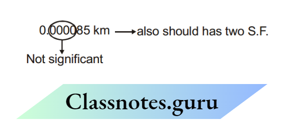
Now if we want to display the measurement in some different units, the S.F. shouldn’t change (S.F. depends only on the accuracy of measurement) Number of S.F. is always conserved, change of units cannot change the S.F. Suppose measurement was done using mm scale, and we get = 85 mm (Two S. F.) If we want to display it in other units.
All should have two S.F.
The following rules support the conservation of S.F.

Rule 4:
From the previous example, we have seen that 8 and 5, So leading Zeros are not significant.

In the number less than one, all zeros after the decimal point and to the left of the first non-zero digit are insignificant (arises only due to change of unit)
0.000305 has three S.F.
⇒ 3.05 × 10⁻⁴ has three S.F.
Rule 5:
From the previous example, we have also seen that, 8 and 5. So the trailing zeros are also not
significant.
The terminal or trailing zeros in a number without a decimal point are not significant. (Also arises only due to change of unit)
154 m = 15400 cm = 15400 mm = 154 × 109 nm
All have only three S.F. All trailing zeros are insignificant
Rule 6:
There are certain measurements, that are exact i.e
Number of apples are = 12 (exactly) = 12.000000……….∞
This type of measurement is infinitely accurate so, it has ∞ S.F.
- Numbers of students in class = 125 (exact)
- Speed of light in the vacuum = 299,792,458 m/s (exact)
Solved Examples:
Example 1. Count the total number of S.F. in 3.0800
Solution: S.F. = Five, as trailing zeros after decimal place are significant.
Example 2. Count the total number of S.F. in 0.00418
Solution: S.F. = Three, as leading zeros are not significant.
Example 3. Count the total number of S.F. in 3500
Solution: S.F. = Two, the trailing zeros are not significant.
Example 4. Count the total number of S.F. in 300.00
Solution: S.F. = Five, trailing zeros after the decimal point are significant.
Example 5. Count the total number of S.F. in 5.003020
Solution: S.F. = Seven, the trailing zeros after the decimal place are significant.
Example 6. Count the total number of S.F. in 6.020 × 10²³
Solution: S.F. = Four; 6, 0, 2, 0; remaining 23 zeros are not significant.
Example 7. Count the total number of S.F. in 1.60 × 10⁻¹⁹
Solution: S.F. = Three; 1, 6, 0; remaining 19 zeros are not significant.
Operations according to significant figures:
Now let’s see how to do arithmetic operations ie. addition, subtraction, multiplication, and division according to significant figures
Addition ←→ subtraction
For this, let’s consider the example given below. In a simple pendulum, the length of the thread is measured (from mm scale) as 75.4 cm. and the radius of the bob is measured (from vernier) as 2.53 cm. Find leg = l+ radius

NEET Physics Chapter 2 Measurement Errors and Experiments Study Notes
l is known upto 0.1 cm( first decimal place) only. We don’t know what is at the next decimal place. So we can write l =75.4 cm = 75.4? cm and the radius r = 2.53 cm. If we add l and r, we don’t know which number will be added with 3. So we have to leave that position.
leq= 75.4? + 2.53 = 77.9? cm = 77.9 cm
Rules for Addition ←→ subtraction: (based on the previous example)
- First, do the addition/subtraction in the normal manner.
- Then round off all quantities to the decimal place of the least accurate quantity.

Rules for Multiply ←→ Division
Suppose we have to multiply 2.11 x 1.2 = 2.11. x 1.2?

- Multiply divide in the normal manner.
- Round off the answer to the weakest link (number having the least S.F.)

Solved Example
Example 8. A cube has a side l= 1.2 × 10⁻² m. Calculate its volume
Solution: l= 1.2 × 10⁻²

Rules of Rounding off
If the removable digit is less than 5 (50%); drop it.
⇒ \(47.833 \frac{\text { Round off }}{\text { till one decimal place }} 47.8\)
If the removable digit is greater than 5(50%), increase the last digit by 1.
⇒ \(47.862 \frac{\text { Round off }}{\text { till one decimal place }} 47.9\)

Example 9. Using a screw gauge radius of the wire was found to be 2.50 mm. The length of wire found by mm. scale is 50.0 cm. If the mass of the wire was measured as 25 gm, the density of the wire in the correct S.F. will be (use π = 3.14 exactly )
Solution:

Least Count
We have studied (from page 1) that no measurement is perfect. Every instrument can measure upto a certain accuracy; called least count.
Least count: The Smallest quantity an institution can measure

Permissible Error
Error in measurement due to the limitation (least count) of the instrument, is called permissible error. From the mm scale → we can measure upto 1 mm accuracy (least count = 1mm). From this, we will get measurements like Δl = 34 mm
But if from any other instrument, we get l= 34.5 mm then max permissible error (Δl) = 0.1 mm, and if from a more accurate instrument, we get l= 34.527 mm then max permissible error (Δl) = 0.001 mm = place value of last number.
Max. Permissible Error In Result Due To Error In Each Measurable Quantity:
Let Result f(x, y) contain two measurable quantities x and y
Let error in x = ± Δx i.e. x Δ (x – Δx, x + Δx) error in y = ± Δy i.e. y Δ (y – Δy, y + Δy)
Case: (1) If f(x, y) = x + y df = dx + dy error in f = Δf = ± Δx ± Δy max possible error in f = (Δf)max = max of (± Δx ± Δy) (Δf)max = Δx + Δy
Case: (2) If f = x – y df = dx – dy (Δf) = ± Δx + Δy
max possible error in f = (Δf)max = max of (± Δx± Δy)
(Δf)max = Δx + Δy
For getting a maximum permissible error, the sign should be adjusted, so that errors get added up to give maximum effect
i.e. f = 2x – 3y – z
(Δf)max = 2Δx + 3Δy + Δz
Solved Examples
Example 11. In resonance tube exp. we find l1 = 25.0 cm and l2 = 75.0 cm. The least count of the scale used to measure l is 0.1 cm. If there is no error in frequency What will be max permissible error in speed of sound (take f0 = 325 Hz.)
Solution: V = 2f0 (l2– l1)
(dV) = 2f0 (dl2 – dl1)
(ΔV)max = max of [2f0(± Δl2 + Δl2] = 2f0 (Δl2 + Δl1)
Δl1 = least count of the scale = 0.1 cm
Δl2 = least count of the scale = 0.1 cm
So max permissible error in speed of sound (ΔV)max = 2(325Hz) (0.1 cm + 0.1 cm) = 1.3 m/s Value of V = 2f
0 (l2 – l1) = 2(325Hz) (75.0 cm – 25.0 cm) = 325 m/s so V = ( 325 ± 1.3 ) m/s
Case (3) If f(x, y, z) = (constant) maybe to scatter all the terms, Let’s take log on both sides ln f = ln (constant) + a ln x + b ln y + c ln z
↓ Differentiating both sides
⇒ \(\begin{aligned}
& \frac{d f}{f}=0+a \frac{d x}{x}+b \frac{d y}{y}+c \frac{d z}{z} \\
& \frac{\Delta f}{f}= \pm a \frac{\Delta x}{x} \pm b \frac{\Delta y}{y} \pm c \frac{d z}{z}
\end{aligned}\)
⇒\(\begin{aligned}
& \left(\frac{\Delta f}{f}\right)_{\max }=\max \text { of }\left( \pm \mathrm{a} \frac{\Delta x}{x} \pm \mathrm{b} \frac{\Delta y}{y} \pm c \frac{\Delta z}{z}\right) \\
& \text { i.e. } \quad f=15 x^2 y^{-3 / 2} z^{-5}
\end{aligned}\)
⇒ \(\begin{aligned}
& \frac{d f}{f}=0+2 \frac{d x}{x}-\frac{3}{2} \frac{d y}{y}-5 \frac{d z}{z} \\
& \frac{\Delta f}{f}= \pm 2 \frac{\Delta x}{x} \mp \frac{3}{2} \frac{\Delta y}{y} \mp 5 \frac{d z}{z}
\end{aligned}\)
⇒ \(\left(\frac{\Delta f}{f}\right)_{\max }=\max \text { of }\left( \pm 2 \frac{\Delta x}{x} \mp \frac{3}{2} \frac{\Delta y}{y} \mp 5 \frac{\Delta z}{z}\right)\)
⇒ \(\left(\frac{\Delta f}{f}\right)_{\max }=2 \frac{\Delta x}{x}+\frac{3}{2} \frac{\Delta y}{y}+5 \frac{\Delta z}{z}\)
Solved Examples
Example 12. If the measured value of resistance R = 1.05Ω, wire diameter d = 0.60 mm, and length l= 75.3 cm. If the maximum error in resistance measurement is 0.01Ω and the least count of diameter and length measuring device are 0.01 mm and 0.1 cm respectively, then find max. permissible error.
⇒ \(\text { in resistivity } \quad \rho=\frac{R\left(\frac{\pi d^2}{4}\right)}{\ell}\)
Solution: \(\left(\frac{\Delta \rho}{\rho}\right)_{\max }=\frac{\Delta R}{R}+2 \frac{\Delta d}{d}+\frac{\Delta \ell}{\ell}\)
ΔR = 0.01
Δd = 0.01 mm (least count)
Δl = 0.1 cm (least count)
⇒ \(\left(\frac{\Delta \rho}{\rho}\right)_{\max }=\left(\frac{0.01 \Omega}{1.05 \Omega}+2 \frac{0.01 \mathrm{~mm}}{0.60 \mathrm{~mm}}+\frac{0.1 \mathrm{~cm}}{75.3 \mathrm{~cm}}\right) \times 100=4.3 \% .\)
Example 13. In Ohm’s law experiment, the potential drop across a resistance was measured as v = 5.0 volt and the current was measured as i = 2.0 amp. If the least count of the voltmeter and ammeter are 0.1 V and 0.01A respectively then find the maximum permissible error in resistance.
solution: \(R=\frac{v}{i}=v \times i^{-1}\)
⇒ \(\left(\frac{\Delta R}{R}\right)_{\max }=\frac{\Delta v}{v}+\frac{\Delta i}{i}\)
Δv = 0.1 volt (least count)
Δi = 0.01 amp (least count)
⇒ \(\%\left(\frac{\Delta R}{R}\right)_{\max }=\left(\frac{0.1}{5.0}+\frac{0.01}{2.00}\right) \times 100 \%=2.5 \%\)
Example 14. In Searle’s exp to find Young’s modulus, the diameter of wire is measured as D = 0.050 cm, the length of wire is L = 125 cm, and when a weight, m = 20.0 kg is put, extension in the length of the wire was found to be 0.100 cm. Find the maximum permissible error in Young’s modulus (Y).
Solution: \(\frac{\mathrm{mg}}{\pi \mathrm{d}^2 / 4}=Y\left(\frac{\mathrm{x}}{\ell}\right) \quad \Rightarrow \quad Y=\frac{\mathrm{mg} \ell}{(\pi / 4) \mathrm{d}^2 x}\)
⇒ \(\left(\frac{\Delta Y}{Y}\right)_{\max }=\frac{\Delta m}{m}+\frac{\Delta \ell}{\ell}+2 \frac{\Delta d}{d}+\frac{\Delta x}{x}\)
Here no information on least count is given so the maximum permissible error is = place value of the last number.
m = 20.0 kg m = 0.1 kg (place value of the last number)
l= 125 cm = 1 cm (place value of last number)
d = 0.050 cm d = 0.001 cm (place value of the last number)
x = 0.100 cm x = 0.001 cm (place value of the last number)
⇒ \(\left(\frac{\Delta Y}{Y}\right)_{\max }=\left(\frac{0.1 \mathrm{~kg}}{20.0 \mathrm{~kg}}+\frac{1 \mathrm{~cm}}{125 \mathrm{~cm}}+\frac{0.001 \mathrm{~cm}}{0.05 \mathrm{~cm}} \times 2+\frac{0.001 \mathrm{~cm}}{0.100 \mathrm{~cm}}\right) \times 100 \%=6.3 \%\)
Example 15. To find the value of ‘g’ using a simple pendulum. T = 2.00 sec; l = 1.00 m was measured. Estimate maximum permissible error in ‘g’. Also, find the value of ‘g’. ( use pi2 = 10 )
Solution:
⇒ \(\mathrm{T}=2 \pi \sqrt{\frac{\ell}{\mathrm{g}}} \quad \Rightarrow \quad \mathrm{g}=\frac{4 \pi^2 \ell}{\mathrm{T}^2}\)
⇒ \(\left(\frac{\Delta \mathrm{g}}{\mathrm{g}}\right)_{\max }=\frac{\Delta \ell}{\ell}+2 \frac{\Delta \mathrm{T}}{\mathrm{T}} \quad=\left(\frac{0.01}{1.00}+2 \frac{0.01}{2.00}\right) \times 100 \% . \quad=2 \%\)
⇒ \(\text { value of } \mathrm{g}=\frac{4 \pi^2 \ell}{\mathrm{T}^2}=\frac{4 \times 10 \times 1.00}{(2.00)^2}=10.0 \mathrm{~m} / \mathrm{s}^2\)
⇒ \(\left(\frac{\Delta \mathrm{g}}{\mathrm{g}}\right)_{\max }=2 / 100 \text { so } \frac{\Delta \mathrm{g}_{\max }}{10.0}=\frac{2}{100} \text { so } \quad(\Delta \mathrm{g})_{\max }=0.2=\text { max error in ‘ } \mathrm{g} \text { ‘ }\)
So g = (10.0+0.2) m/s2
Other Types Of Errors:
1. Error due to external Causes:
These are the errors that arise due to reasons beyond the control of the experimentalist, e.g., change in room temperature, atmospheric pressure, humidity, variation of the accretion due to gravity, etc.
A suitable correction can, however, be applied for these errors if the factors affecting the result are also recorded.
2. Instrumental errors:
Every instrument, however cautiously manufactured, possesses imperfection to some extent. As a result of this imperfection, the measurements with the instrument cannot be free from errors.
Errors, however small, do occur owing to the inherent manufacturing defects in the measuring instruments and are called instrumental errors.
These errors are of constant magnitude and suitable corrections can be applied for these errors. e.i.. Zero errors in vernier calipers, and screw gauge, backlash errors in screw gauge, etc.
Personal or chance error:
Two observers using the same experiment setup, do not obtain the same result. Even the observations of a single experimentalist differ when it is repeated several times by him or her.
Such errors always occur inspire of the best and honest efforts on the part of the experimentalist and are known as personal errors. These errors are also called chance errors as they depend upon chance.
The effect of the chance error on the result can be considerably reduced by taking a large number of observations and then taking their mean. How to take the mean, is described in the next point.
Measurement Errors and Experiments Notes for NEET Physics
4. Errors in Averaging :
Suppose to measure some quantity, we take several observations, a1, a2, a3…. an. To find the absolute error in each measurement and percentage error, we have to follow these steps (a)
First of all mean of all the observations is calculated: a mean = (a1+ a2 +a3 +…+ an) / n. The mean of these values is taken as the best possible value of the quantity under the given conditions of measurements.
Absolute Error:
The magnitude of the difference between the best possible or mean value of the quantity and the individual measurement value is called the absolute error of the measurement. The absolute error in an individual measured value is:
⇒ \(\Delta a_n=\left|a_{\text {mean }}-a_n\right|\)
The arithmetic mean of all the absolute errors is taken as the final or mean absolute error.
⇒ \(\Delta \mathrm{a}_{\text {mean }}=\left(\left|\Delta \mathrm{a}_1\right|+\left|\Delta \mathrm{a}_2\right|+\left|\Delta \mathrm{a}_3\right|+\ldots \ldots \ldots . .+\left|\Delta \mathrm{a}_n\right|\right) / \mathrm{n}\)
⇒ \(\Delta a_{\text {mean }}=\left(\sum_{i=1}^n\left|\Delta a_i\right|\right) / n\)
⇒ \(\text { we can say } \mathrm{a}_{\text {mean }}-\Delta \mathrm{a}_{\text {mean }} \leq \mathrm{a} \leq \mathrm{a}_{\text {mean }}+\Delta \mathrm{a}_{\text {mean }}\)
Relative and Percentage Error
Relative error is the ratio of the mean absolute error and arithmetic mean
⇒ \(\text { Relative error }=\frac{\Delta \mathrm{a}_{\text {mean }}}{\mathrm{a}_{\text {mean }}}\)
When the relative error is expressed in percent, it is called the percentage error. Thus,
⇒ \(\text { Percentage error }=\frac{\Delta \mathrm{a}_{\text {mean }}}{\mathrm{a}_{\text {mean }}} \times 100 \%\)
Solved Examples
Example 16. In some observations, values of ‘g’ are coming as 9.81, 9.80, 9.82, 9.79, 9.78, 9.84, 9.79, 9.78, 9.79, and 9.80 m/s2. Calculate absolute errors and percentage errors in g.
Solution:

Percentage error \(=\frac{\Delta g_{\text {mean }}}{g_{\text {mean }}} \times 100=\frac{0.014}{9.80} \times 100 \%=0.14 \%\)
so ‘g’ = ( 9.80 ± 0.014 ) m/s2
Experiment – 1
Screw gauge (Micrometer)

Screw gauge is used to measure closely upto \(\left(\frac{1 \mathrm{~mm}}{100}\right)\) How can it divide 1 mm in 100 parts! To divide 1 mm into 100 parts, a screw is used. In one rotation, the screw (spindle) moves forward by 1 mm. (Called the pitch of the screw ) The rotation of the screw (spindle) is divided into 100 parts (called circular scale), hence 1 mm is divided into 100 parts

1 rotation= 1 mm
100 circular parts= 1 mm
so 1 circular part= \(\frac{1 \mathrm{~mm}}{100}=\text { Least count of screw gauge }\)
So let’s generalize it

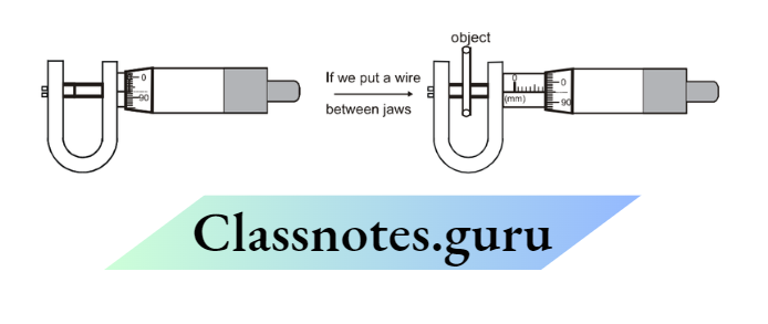
How to find the thickness of an object by screw gauge
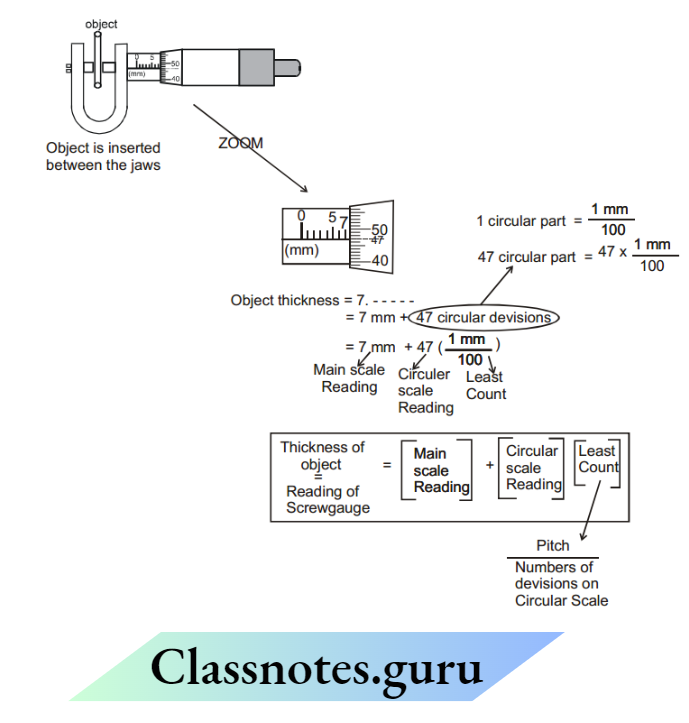
Description of screw gauge:

The object to be measured is put between the jaws. The sleeve is a hollow part, fixed with the frame and the main scale is printed on it. The spindle and thimble are welded and move together utilizing a screw.
The circular scale is printed on the thimble as shown. It generally consists of 100 divisions (sometimes 50 divisions also). The main scale has mm marks (Sometimes it also has 1/2 mm marks below mm marks.)
(Usually, if the pitch of the screw gauge is 1mm then there are 1mm marks on the main scale and if the pitch is 1/2 mm then there are 1/2 mm marks also)
This instrument can read upto 0.01 mm (10 um) with accuracy which is why it is called a micrometer
Solved Examples
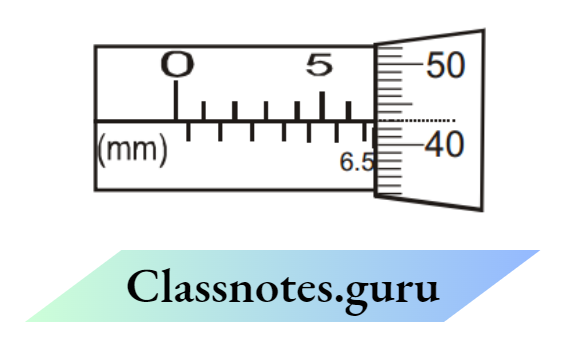
Example 17. Read the normal screw gauge
- The main scale has only mm marks.
- In a complete rotation, the screw advances by 1 mm.
- The circular scale has 100 divisions
Solution:

Example 18. Read the screw gauge
- Main scale has \(\frac{1}{2} \mathrm{~mm}\) marks
- In complete rotation, the screw advances by \(\frac{1}{2}\) mm.
- The circular scale has 50 divisions.
Solution:
Example 19. Read the screw gauge shown below:
- Main scale has \(\frac{1}{2} \mathrm{~mm}\) marks
- In complete rotation, the screw advances by \(\frac{1}{2} \mathrm{~mm} \text {. }\)
- The circular scale has 50 divisions.
Example 20. A wire of resistance R = 100.0Ω and length l = 50.0 cm is put between the jaws of the screw gauge. Its reading is shown in the figure. The pitch of the screw gauge is 0.5 mm and there are 50 divisions on a circular scale. Find its resistivity in correct significant figures and maximum permissible error in p (resistivity).
Solution:

⇒ \(R=\frac{\rho \ell}{\pi d^2 / 4}\)
⇒ \(\rho=\frac{R \pi d^2}{4 \ell}=\frac{(100.0)(3.14)\left(8.42 \times 10^{-3}\right)}{4\left(50.0 \times 10^{-2}\right)}=1.32 \Omega / \mathrm{m}\)
⇒ \(\frac{d \rho}{\rho}=\frac{d R}{R}+\frac{2 d(D)}{D}+\frac{d \ell}{\ell}=\frac{0.1}{100.0}+2 \times \frac{0.01}{8.42}+\frac{0.1}{50}=0.00537(\approx 0.52 \%)\)
Answer:
Example 21. In a complete rotation, the spindle of a screw gauge advances by \(\frac{1}{2} \mathrm{~mm} \text {. }\) There are 50 divisions on a circular scale. The main scale has \(\frac{1}{2} \mathrm{~mm}\) mm marks → (is graduated to \(\frac{1}{2} \mathrm{mm}\) or has least count \(=\frac{1}{2} \mathrm{~mm}\) If a wire is put between the jaws, 3 main scale divisions are visible, and 20 divisions of circular scale co-inside with the reference line. Find the diameter of the wire in the correct S.F
Solution: Diameter of wire \(\left(3 \times \frac{1}{2} \mathrm{~mm}\right)+(20)\left(\frac{1 / 2 \mathrm{~mm}}{50}\right)=1.5+0.20=1.70 \mathrm{~mm}\) (The answer should be upto two decimal places because this screw gauges can measure upto 0.01 mm accuracy).
Example 22. In the previous question if the mass of the wire is measured as 0.53 kg and the length of the wire is measured by an mm scale and is found to be 50.0 cm, find the density of the wire in correct significant figures.
Solution: \(\rho=\frac{\mathrm{m}}{\left(\frac{\pi \mathrm{d}^2}{4}\right) \ell}=\frac{\left(0.53 \times 10^3\right) \times 4}{(3.14)\left(1.70 \times 10^{-3}\right)^2\left(50 \times 10^{-2}\right)} \mathrm{g} / \mathrm{m}^3=4.7 \times 10^8 \text { (2 S.F.) }\)
Example 23. Two measure diameter of a wire, a screw gauge is used. The main scale division is 1 mm. In a complete rotation, the screw advances by 1 mm and the circular scale has 100 divisions. The reading of the screw gauge is shown in the figure.

If there is no error in mass measurement, but an error in length measurement is 1%, then find
max. Possible error in density.
Solution: \(\rho=\frac{\mathrm{m}}{\left(\frac{\pi \mathrm{d}^2}{4}\right) \ell} \quad \Rightarrow \quad\left(\frac{\Delta \rho}{\rho}\right)=2 \frac{\Delta \mathrm{d}}{\mathrm{d}}+\frac{\Delta \ell}{\ell}\)
Δd = least count of \(\frac{1 \mathrm{~mm}}{100}=0.01 \mathrm{~mm}\) and d = 3.07 mm from the figure so \(\left(\frac{\Delta \rho}{\rho}\right)_{\max }=\left(2 \times \frac{0.01}{3.07}+\frac{1}{100}\right) \times 100 \% \quad \Rightarrow \quad\left(\frac{\Delta \rho}{\rho}\right)_{\max }=1.65 \% \text {. }\)
Zero Error:
If there is no object between the jaws (i.e. jaws are in contact), the screw gauge should give zero reading. But due to extra material on jaws, even if there is no object, it gives some excess reading. This excess. Reading is called zero error:

Solved Examples
Example 24. Find the thickness of the wire. The main scale division is 1 mm. In a complete rotation, the screw advances by 1 mm and the circular scale has 100 divisions.

Solution: Excess reading (Zero error) = 0.03 mm It is giving 7.67 mm in which there is 0.03 mm excess reading, which has to be removed ( subtracted) so actual reading = 7.67 – 0.03 = 7.64 mm
Example 25. Find the thickness of the wire. The main scale division is 1 mm. In a complete rotation, the screw advances by 1 mm and the circular scale has 100 divisions. The zero error of the screw gase is –0.07 mm
Solution: Excess reading (Zero error) = – 0.07mm It is giving 7.95 mm in which there is -0.07 mm excess reading, which has to be removed ( subtracted) so actual reading = 7.95 -(- 0.07) = 8.02 mm.
Zero Correction:
- Zero correction is an invert of zero error:
- zero correction = – (zero error)
Actual reading = observed reading – zero error = observed reading + Zero correction
Experiment 2
Vernier calipers
It is used to measure accurately upto 0.1 mm.


- On the upper plate, the main scale is printed which is simply an mm scale.
- On the lower plate, the vernier scale is printed, which is a bit compressed scale. Its one part is 0.9 mm. (10 vernier scale divisions = 9 mm ⇒ 1 vernier scale division = 0.9 mm)
- The object which is to be measured is fitted between the jaws as shown.
NEET Physics Class 12 Measurement Errors Notes
How to read vernier calipers:

Now let’s see How the slight difference between 1 MSD and 1 VSD reflects as least count

Required length = 13 mm + x =?
at point ‘A’, the main scale and vernier scale are matching
so length OA along main Scale = length OA along Vernier Scale
13 mm +3 (Main scale division) = ( 13 mm + x ) + 3 (vernier Scale division )
Get 13 mm + x = 13 mm + 3 (Main scale division – vernier Scale division)
= 13 mm + 3 ( 1 mm – 0.9 mm )

Hence the slight difference between 1 MSD (1 mm ) and 1 VSD (0.9 mm ) reflects as least count (0.1 mm)

Example 26. Read the vernier. 10 divisions of the vernier scale match with 9 divisions of the main scale

Solution: 10 vernier scale divisions = 9 mm
1 vernier scale division = 0.9 mm
least count = (Main scale division – vernier Scale division)
= 1 mm – 0.9 mm (from figure)
= 0.1 mm
Thickness of the object = (main scale reading) + (vernier scale Reading) (least count )
So thickness of the object = 15 mm + (6) (0.1mm ) = 15.6 mm
Example 27. Read the special type of vernier. 20 divisions of the vernier scale match with 19 divisions of main scale.
Solution: 20 vernier scale divisions = 19 mm
1 vernier scale division \(=\frac{19}{20} \mathrm{~mm}\)
where least count = (Main scale division – vernier Scale division)
= 1 mm – 19/20 mm
= 0.05 mm
Thickness of the object = (main scale reading) + (vernier scale Reading) (least count )
So thickness of the object = 13 mm + (12) (0.05mm )
= 13.60 mm
Zero Error:
If there is no object between the jaws (ie. jaws are in contact ), the vernier should give zero reading. But due to some extra material on the jaws, even if there is no object between the jaws, it gives some excess Reading. This excess reading is called a zero error
Example 28. In the vernier calipers, 9 main scale divisions match with 10 vernier scale divisions. The thickness of the object using the defective vernier calipers will be :


Example 29. In the vernier calipers, 9 main scale divisions match with 10 vernier scale divisions.
The thickness of the object using the defective vernier calipers will be :

Solution: From the first figure, Excess reading (zero error ) = 0.6 mm If an object is placed, vernier gives 14.6 mm in which there is 0.6 mm excess reading, which has to be subtracted. So actual thickness = 14.6 – 0.6 = 14.0 mm we can also do it using the formula

Example 30. The main scale reading is –1 mm when there is no object between the jaws. In the vernier calipers, 9 main scale divisions match with 10 vernier scale divisions. The thickness of the object using the defective vernier calipers will be:

Solution: Zero error = main scale reading + ( vernier scale reading ) ( least count ) = –1 mm + 6 (0.1 mm) = –0.4 mm observed reading = 11.8 mm So actual thickness = 11.8 – (-0.4) = 12.2 mm.
Zero Correction:
- Zero correction is an invert of zero error.
- Zero correction = – ( zero error )
- In example 28, zero error was 0.6 mm, so zero correction will be – 0.6 mm
- In example 29, zero error was -0.4 mm, so zero correction will be + 0.4 mm
Example 31. The main scale of the vernier calipers reads 10 mm in 10 divisions. 10 divisions of the Vernier scale coincide with 9 divisions of the main scale. When the two jaws of the calipers touch each other, the fifth division of the vernier coincides with 9 main scale divisions and the zero of the vernier is to the right of zero of the main scale.
When a cylinder is tightly placed between the two jaws, the zero of the vernier scale lies slightly behind 3.2 cm and the fourth vernier division coincides with a main scale division. The diameter of the cylinder is.
Solution: Zero error = 0.5 mm = 0.05 cm. Observed reading of cylinder diameter = 3.1 cm + (4) (0.01 cm). = 3.14 cm Actual thickness of cylinder = (3.14) – (0.05). = 3.09 cm
Example 32. In the previous question if the length of the cylinder is measured as 25 mm, and the mass of the cylinder is measured as 50.0 gm, find the density of the cylinder (gm/cm 3) in proper significant figures
Solution:
⇒ \(\rho=\frac{m}{\pi\left(d^2 / 4\right) h}\)
⇒ \(\rho=\frac{(50.0) \mathrm{gm}}{3.14 \times(3.09 / 2)^2 \times\left(25 \times 10^{-1}\right) \mathrm{cm}^3}=2.7 \mathrm{gm} / \mathrm{cm}^3 \text { (in two S.F.) }\)
Experiment 3
Determining the value of ‘g’ using a simple pendulum

In this exp., a small spherical bob is hung with a cotton thread. This arrangement is called a sample pendulum. The bob is displaced slightly and allowed to oscillate. To find the period, the time taken for 50 oscillations is noted using a stopwatch
⇒ \(\text { Theoretically } T=2 \pi \sqrt{\frac{\mathrm{L}}{\mathrm{g}}} \quad \Rightarrow \quad \mathrm{g}=4 \pi^2 \frac{\mathrm{L}}{\mathrm{T}^2}\)
where L = Equivalent length of pendulum = length of thread (l) + radius (r) of bob,
T = time period of the simple pendulum \(=\frac{\text { Time taken for } 50 \text { oscillations }}{50}\)
so ‘g’ can be easily determined by equation …(1).
Graphical method to find ‘g’:
⇒ \(\mathrm{T}^2=\left(\frac{4 \pi^2}{g}\right) \mathrm{L}\) \(\text { so, } \mathrm{T}^2 \propto \mathrm{L}\)
Find T for different values of L.
Plot T2 v/s L curve. From equation (2), it should be a straight line, with slope \(=\left(\frac{4 \pi^2}{g}\right)\)
Find slope of T2 v/s L graph and equate it to \(\left(\frac{4 \pi^2}{g}\right)\) and get ‘g’.

Example 33. In certain observation, we got l= 23.2 cm, r = 1.32 cm, and the time taken for 10 oscillations was 10.0 sec. Estimate the value of ‘g’ in a proper significant figure. (take π² = 10)
Solution : Equivalent length of pendulum L = 23.2 cm + 1.32 cm
= 24.5 cm (according to the addition rule of S.F.)
And time period \(T=\frac{10.0}{10}=1.00\)
⇒ \(\text { get } \mathrm{g}=4 \pi^2 \frac{\mathrm{L}}{\mathrm{T}^2}=4 \times 10 \frac{24.5 \mathrm{~cm}}{(1.00)^2} \text { (in 3 S.F.) }\)
⇒ \(=4 \times 10 \times \frac{24.5 \times 10^{-2} \mathrm{~m}}{(1.00)^2 \mathrm{sec}^2}=9.80 \mathrm{~m} / \mathrm{sec}^2\)
Example 34. For different values of L, we get different values of ‘T’. The curve between L v/s T² is shown. Estimate ‘g’ from this curve. (take π² = 10)

Solution: \(\mathrm{L}=\left(\frac{\mathrm{g}}{4 \pi^2}\right) \mathrm{T}^2\) \(\mathrm{L} v / s \mathrm{~T}^2=\left(\frac{\mathrm{g}}{4 \pi^2}\right)\) slope \(=\frac{0.49}{2}=\frac{\mathrm{g}}{4 \pi^2} \quad \Rightarrow \quad \mathrm{g}=9.8 \mathrm{~m} / \mathrm{sec}^2\)
Maximum permissible error in ‘g’ due to error in measurement of l, r, and T.
⇒ \(\mathrm{g}=4 \pi^2 \frac{(\ell+r)}{(\mathrm{t} / 50)^2}=4 \pi^2(2500) \frac{\ell+r}{\mathrm{t}^2}\)
⇒ \(\ln \mathrm{g}=\ln 4 \pi^2(2500)+\ln (\ell+\mathrm{r})-2 \ln (\mathrm{t}) \quad\left(\frac{\Delta \mathrm{g}}{\mathrm{g}}\right)_{\max }=\frac{\Delta \ell+\Delta \mathrm{r}}{\ell+\mathrm{r}}+2 \frac{\Delta \mathrm{t}}{\mathrm{t}}\).
Solved Examples
Example 35. In certain observations we got = 23.2 cm, r = 1.32 cm, and the time taken for 10 oscillations was 10.0 sec. Find the maximum permissible error in (g)
solution:
⇒ \(\begin{array}{lll}
\ell=23.2 & \rightarrow & \Delta \ell=0.1 \mathrm{~cm} \\
\mathrm{r}=1.32 \mathrm{~cm} & \rightarrow & \Delta \mathrm{r}=0.01 \mathrm{~cm} \\
\mathrm{t}=10.0 \mathrm{sec} & \rightarrow & \Delta \mathrm{t}=0.1 \mathrm{sec}
\end{array}\)
⇒ \(\left(\frac{\Delta \mathrm{g}}{\mathrm{g}}\right)_{\max }=\left(\frac{0.1 \mathrm{~cm}+0.01 \mathrm{~cm}}{23.2 \mathrm{~cm}+1.32 \mathrm{~cm}}+2 \frac{0.1 \mathrm{sec}}{10.0 \mathrm{sec}}\right) \times 100 \%=2.44 \%\)
Example 36. Time is measured using a stopwatch of the least count of 0.1 seconds. In 10 oscillations, the time taken is 20.0 seconds. Find the maximum permissible error in the period.
Solution: \(\begin{aligned}
& \mathrm{T}=\frac{\text { Total time }}{\text { Total oscillation }}=\frac{\mathrm{t}}{10} \quad \Rightarrow \quad \Delta \mathrm{T}=\frac{\Delta \mathrm{t}}{10}=\frac{0.1}{10} \\
& \Delta \mathrm{T}=0.01 \text { second. }
\end{aligned}\)
Example 37. A student experiments determination of \(\mathrm{g}\left(=\frac{4 \pi^2 \ell}{\mathrm{T}^2}\right), \quad ” \ell ” \approx 1 \mathrm{~m}\) and he commits an error of “Δl”. For T he takes the time of n oscillations with the stopwatch of least count Δt. For which of the following data, the measurement of g will be most accurate?
Solutions:
⇒ \(\begin{gathered}
\text { Here } \mathrm{T}=\frac{\text { total time }}{\text { total oscillation }}=\frac{\mathrm{t}}{\mathrm{n}} \text { so } \mathrm{dT}=\frac{\mathrm{dt}}{\mathrm{n}} \\
\frac{\Delta \mathrm{g}}{\mathrm{g}}=\frac{\Delta \mathrm{L}}{\mathrm{L}}+2 \frac{\Delta \mathrm{T}}{\mathrm{T}}
\end{gathered}\)
⇒ \(\frac{\Delta g}{g}=\frac{0.5}{1}+2 \frac{0.1 / 20}{T}\)
⇒ \(\frac{\Delta g}{g}=\frac{0.5}{1}+2 \frac{0.1 / 50}{T}\)
⇒ \(\frac{\Delta g}{g}=\frac{0.5}{1}+2 \frac{0.02 / 20}{T}\)
⇒ \(\frac{\Delta g}{g}=\frac{0.1}{1}+2 \frac{0.05 / 50}{T}\)
So % error in g will be minimum in option (D)
Experiment 4
Determining Young’s Modulus of a given wire by “Searle’s Method“: An elementary method: To determine Young’s Modulus, we can perform an ordinary experiment. Let’s hang a weight ‘m’ from a wire

from Hook’s law: \(\frac{\mathrm{mg}}{\mathrm{A}}=\mathrm{Y}\left(\frac{\mathrm{x}}{\ell_0}\right) \quad \mathrm{x}=\left(\frac{\ell_0}{\pi \mathrm{r}^2 \mathrm{Y}}\right) \mathrm{mg}\)
If we change the weight, the elongation of the wire will increase proportionally.
If we plot elongation v/s mg, we will get a straight line.
By measuring its slope and equating it to \(\left(\frac{\ell_0}{\pi r^2 Y}\right)\) we can estimate Y.
Limitations in this ordinary method
1. For small loads, there may be some bends or kinks in the wire.

So we had better start with some initial weight (say 2 kg). So that the wire becomes straight.
2. There is a slight difference in the behavior of wire underloading and unloading load

- So we had better take the average during loading and unloading.
- The average load will be more and more linear or accurate.

Modification in “Searle’s Method”.
To keep the experimental wire straight and kink-free, we start with some dead weight (2 kg)

Now we gradually add more and more weight. The extra elongation (Δx) will be proportional to extra weight (Δw).
⇒ \(x=\frac{\ell_0}{\pi r^2 Y} w \quad \Rightarrow \quad \Delta x=\frac{\ell_0}{\pi r^2 Y}(\Delta w)\)
so let’s plot Δx v/s Δw, the slope of which will be \(=\left(\frac{\ell_0}{\pi r^2 Y}\right)\)

Measurement of Young’s modulus.
To measure extra elongation, compared to the initial loaded position, we use a reference wire, also carrying a 2 kg load (dead weight). This method of measuring elongation by comparison also cancels the side effect of tamp and yielding of support.
Observations:
- Initial Reading = x0 = 0.540 mm. (Micrometer Reading without extra load)
- Radius of wire = 0.200 mm. (using screw gauge)

Measurement of extra extension due to extra load.

Method 1
Plot Δx v/s Δw (=Δm g)

⇒ \(\text { slope }=\frac{B P}{A P}=\ldots \ldots . .=\frac{\ell}{Y\left(\pi r^2\right)} \Rightarrow Y=\)
Method: 2
→ Between observation (1) (6)
→ and (2) (7)
→ and (3) (8) 2.5 kg extra weight is added
→ and (4) (9)
→ and (5) (10)
→→ → → So elongation from observation (1) (6), (2) (7), (3) (8), (4) (9), and → (5) (10) will be due to extra 2.5 kg wt. So we can find elongation due to 2.5 kg wt from x6 – x1, x5 – x2, x8 – x3, or x10 – x5, and then we can find average elongation due to 2.5 kg wt.

⇒ \(\Delta x=(\Delta w)\left(\frac{\ell_0}{\pi r^2 Y}\right)\) where Δw = Δm g = 25 N and (Δx) average = 0.5 cm Putting the values find Y = ………….
Solved Examples
Example 38. The adjacent graph shows the extra extension (x) of a wire of length 1m suspended from the top of a roof at one end with an extra load w connected to the other end. If the cross-sectional area of the wire is 10–6 m2, calculate the Young’s modulus of the material of the wire.
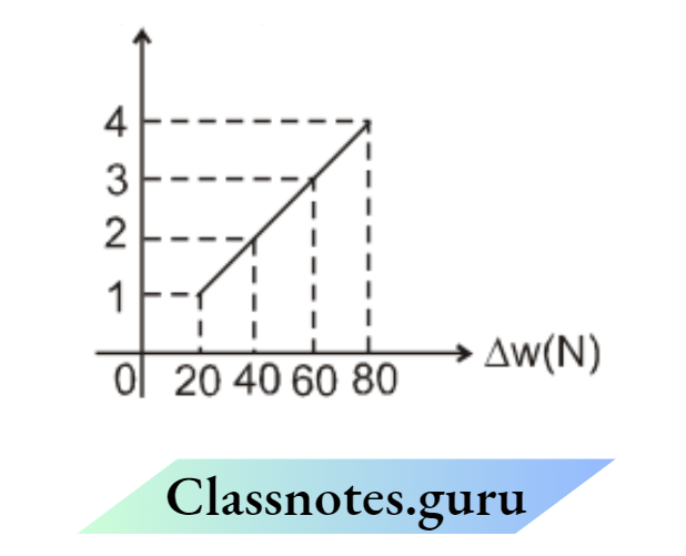
- 2 × 10¹¹ N/m2
- 2 × 10–11 N/m2
- 3 × 10¹³ N/m3
- 2 × 10¹⁶ N/m2
Answer:
Question 39. In the experiment, the curve between Δx and Δw is shown as a dotted line (1). If we use another wire of the same material, but with double length and double radius. Which of the curves is expected?

- 1
- 2
- 3
- 4
Solution: Initially slope \(=\frac{\Delta x}{\Delta w}=\frac{\ell_0}{\left(\pi r^2\right)(Y)}\)
in second case (slope)1 \(=\frac{\left(2 \ell_0\right)}{\pi(2 r)^2 Y}=\frac{1}{2} \frac{\ell_0}{\left(\pi r^2\right) Y}\)
So the slope will be halved.
Answer: 3. 3
NEET Physics Chapter 2 Measurement and Errors Notes
Example 40. Assertion: In Searle’s experiment to find Young’s modulus, a reference wire is also used along with the experiment wire. Reason: Reference wire neutralizes the effect of temperature, yielding of support, and other external factors
- If both Assertion and Reason are true and the Reason is a correct explanation of Assertion
- If both Assertion and Reason and true Reason is not a correct explanation of Assertion.
- If Assertion is true but Reason is false.
- If both Assertion and Reason are false.
Answer: 1. If both Assertion and Reason are true and the Reason is a correct explanation of Assertion
Question 41. If we use very thin and long wire
- Sensitivity \(\left(\frac{\text { output }}{\text { input }}=\frac{\Delta x}{\Delta w}\right)\) of experiment will increase.
- Young’s modulus will remain unchanged
- The wire may break or yield during loading.
- All of the above.
Answer: 4. All of the above.
Maximum permissible error in ‘Y’ due to error in measuring m, l0, r, x: \(Y=\frac{\ell_0}{\pi r^2 x} \mathrm{mg}\)
If there is no tolerance in mass ; max permissible error in Y is \(\left(\frac{\Delta \mathrm{y}}{\mathrm{Y}}\right)_{\max }=\frac{\Delta \ell_0}{\ell_0}+2 \frac{\Delta r}{r}+\frac{\Delta x}{x}\)
Solved Example
Example 42. In Searle’s experiment to find Young’s modulus the diameter of wire is measured as d = 0.050 cm, the length of wire is l = 125 cm and when a weight, m = 20.0 kg is put, extension in the length of wire was found to be 0.100cm. Find the maximum permissible error in Young’s modulus (Y).Use: \(Y=\frac{\mathrm{mg} \ell}{(\pi / 4) \mathrm{d}^2 x} .\)
Solution: \(\frac{\mathrm{mg}}{\pi \mathrm{d}^2 / 4}=Y\left(\frac{\mathrm{x}}{\ell}\right) \Rightarrow \quad \mathrm{Y}=\frac{\mathrm{mg} \ell}{(\pi / 4) \mathrm{d}^2 \mathrm{x}}\)
⇒ \(\left(\frac{d Y}{Y}\right)_{\max }=\frac{\Delta \mathrm{m}}{\mathrm{m}}+\frac{\Delta \ell}{\ell}+2 \frac{\Delta \mathrm{d}}{\mathrm{d}}+\frac{\Delta \mathrm{x}}{\mathrm{x}}\)
m = 20.0 kg Δm = 0.1 kg
Δ= 125 m Δl = 1 cm
d = 0.050 cm Δd = 0.001 cm
x = 0.100 cm Δx = 0.001 cm
⇒ \(\left(\frac{\mathrm{dY}}{\mathrm{Y}}\right)_{\max }=\left(\frac{0.1 \mathrm{~kg}}{20.0 \mathrm{~kg}}+\frac{1 \mathrm{~cm}}{125 \mathrm{~cm}}+\frac{2 \times 0.001 \mathrm{~cm}}{0.05 \mathrm{~cm}}+\frac{0.001 \mathrm{~cm}}{0.100 \mathrm{~cm}}\right) \times 100 \%=6.3 \%\)
Detailed Apparatus and method of Searl’s experiment
Searle’s Apparatus (Static Method)
The figure shows Searle’s apparatus. It consists of two metal frames F1 and F2 hinged together so that they can have only vertical relative motion. A spirit level L is supported at one end on a rigid cross-bar frame whose other end rests on the tip of a micrometer screw S, which moves vertically through the rigid crossbar
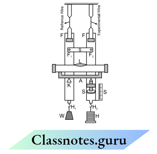
If there is any relative motion between the two frames, the spirit level no longer remains horizontal and the bubble is displaced. To bring the bubble back to its original position, the screw has to be moved up and down.
The distance through which the screw has to be moved gives the relative motion between the two frames. The frames are suspended by two identical long wires of steel from the same rigid horizontal support.
The wire B is an experimental wire and the wire A acts as a reference wire. The two frames are provided with two hooks H1 and H2 at their lower ends. The hook H1 carries a constant weight W to keep the wire taut. To the hook H2, a hanger is attached over which slotted weights can be put to apply the stretching force.
Procedure:
- Measure the length of the experimental wire from the point where it leaves the fixed support to the point where it is fixed in the frame.
- The diameter of the experimental wire is measured with the help of a screw gauge at about five different places and each place in two mutually perpendicular directions.
- Find the pitch and the least count of the micrometer and adjust it such that the bubble in the spirit level is exactly in the center. The initial reading of the micrometer is noted.
- The load on the hanger H2 is gradually increased in steps of 0.5 kg. Observe the reading on the micrometer at each stage after leveling the instrument with the help of the spirit level. To avoid the backlash error, all the final adjustments should be made by moving the screw in the upward direction only. If at any time the screw is raised too much, lower it below the central position and then raise it slowly to the proper position.
- Unload the wire by removing the weights in the same order and taking the reading on the micrometer screw each time. The reading taken for a particular load while loading the wire or unloading the wire should agree closely.
Experiment 5
Determining the specific heat capacity of an unknown liquid using a calorimeter:
The figure shows Regnault’s apparatus to determine the specific heat capacity of an unknown liquid. A solid sphere of known specific heat capacity s1 having mass m1 and initial temperature θ1 is mixed with the unknown liquid filled in a calorimeter.
Let masses of liquid and calorimeter are m2 and m3 respectively, specific heat capacities are s2 and s3 and initially, they were at room temperature θ2.
When the hot sphere is dropped in it, the sphere loses heat and the liquid calorimeter system takes heat. This process continues till the temperature of all the elements becomes the same (sayθ ). Heat lost by hot sphere = m1s1 (θ1 – θ) Heat taken by liquid & calorimeter = m2s2 (θ – θ2) + m3s3 (θ – θ2) If there were no external heat loss Heat given by sphere = Heat taken by liquid-Calorimeter system
⇒ \(\begin{aligned}
& m_1 s_1\left(\theta_1-\theta\right)=m_2 s_2\left(\theta-\theta_2\right)+m_3 s_3\left(\theta-\theta_2\right) \\
\text { Get } \quad & s_2=\frac{m_1 s_1\left(\theta_1-\theta\right)}{m_2\left(\theta-\theta_2\right)}-\frac{m_3 s_3}{m_2}
\end{aligned}\)
By measuring the final (steady state) temperature of the mixture, we can estimate s2: specific heat capacity of the unknown liquid.
To give the initial temperature (θ1) to the sphere, we keep it in the steam chamber (“O”), hanged by thread. Within some time (say 15 min) it achieves a constant temperature θ1.

Now the calorimeter, filled with water (part C) is taken below the steam chamber, the wooden removable disc D is removed, and the thread is cut. The sphere drops into the water-calorimeter system and the mixing starts.
If the sp. heat capacity of liquid (s2) were known and that of the solid ball (s1) is unknown then we can find
⇒ \(s_1=\frac{\left(m_2 s_2+m_3 s_3\right)\left(\theta-\theta_2\right)}{m_1\left(\theta_1-\theta\right)}\)
Solved Examples
Example 43. The mass, specific heat capacity and initial temperature of the sphere were 1000 gm, 1/2 cal/gm°C, and 80°C respectively. The mass of the liquid and the calorimeter are 900 gm and 200 gm, and initially, both were at room temperature 20°C. Both the calorimeter and the sphere are made of the same material. If the steady-state temperature after mixing is found to be 40°C, then the specific heat capacity of the unknown liquid is
- 0.25 cal/gºC
- 0.5 cal/gºC
- 1 cal/gºC
- 1.5 cal/gºC
Answer: 3. 1 cal/gºC
⇒ \(\mathrm{S}_2=\frac{(1000)(1 / 2)\left(80^{\circ}-40^{\circ}\right)}{900\left(40^{\circ}-20^{\circ}\right)}-\frac{(200)(1 / 2)}{900}=1 \mathrm{cal} / \mathrm{gm}^{\circ} \mathrm{C}\)
Example 44. If accidentally the calorimeter remained open to the atmosphere for some time during the experiment, due to which the steady-state temperature comes out to be 30ºC, then total heat loss to surroundings during the experiment, is (Use the specific heat capacity of the liquid from the previous question).
- 20 kcal
- 15 kcal
- 10 kcal
- 8 kcal
Solution: (2) Heat given by the sphere = (1000) (1/2) (80 – 30) = 25,000 cal
Heat absorbed by the water calorimeter system = (900) (1) (40 – 30) + (200) (1/2) (40 – 30) = 10,000 cal.
So heat loss to surrounding = 15,000 cal
Example 45. If the loss in gravitational potential energy due to falling the sphere by h height and heat loss to H surrounding at a constant rate is also taken into account, the energy equation will be modified to
- \(m_1 s_1\left(\theta_1-\theta\right)+\frac{m_1 g h}{J}=m_2 s_2\left(\theta-\theta_2\right)+m_3 s_3\left(\theta-\theta_2\right)-\dot{H} t\)
- \(m_1 s_1\left(\theta_1-\theta\right)-\frac{m_1 g h}{J}=m_2 s_2\left(\theta-\theta_2\right)+m_3 s_3\left(\theta-\theta_2\right)+\dot{H} t\)
- \(m_1 s_1\left(\theta_1-\theta\right)+\frac{m_1 g h}{J}=m_2 s_2\left(\theta-\theta_2\right)+m_3 s_3\left(\theta-\theta_2\right)+\dot{H} t\)
- \(m_1 s_1\left(\theta_1-\theta\right)-\frac{m_1 g h}{J}=m_2 s_2\left(\theta-\theta_2\right)+m_3 s_3\left(\theta-\theta_2\right)-\dot{H} t\)
Solution: 3. \(m_1 s_1\left(\theta_1-\theta\right)+\frac{m_1 g h}{J}=m_2 s_2\left(\theta-\theta_2\right)+m_3 s_3\left(\theta-\theta_2\right)+\dot{H} t\)
Heat generated = \(m_1 s_1\left(\theta_1-\theta\right)+\frac{m_1 g h}{J}\)
Maximum Permissible error in S 1 due to error in measuring θ1, θ2, and θ: To determine the specific heat capacity of an unknown solid,
we uses \(s_{\text {sold }}=\frac{m_1 s_1+m_2 s_2}{m_1}\left(\frac{\theta_{\mathrm{ss}}-\theta_2}{\theta_1-\theta_{\mathrm{ss}}}\right)\)
⇒ \(\mathrm{s}=\frac{\mathrm{m}_1 \mathrm{~s}_1+\mathrm{m}_2 \mathrm{~s}_2}{m_1}\left(\frac{\theta_{\mathrm{ss}}-\theta_2}{\theta_1-\theta_{\mathrm{ss}}}\right) \Rightarrow \frac{\mathrm{ds}}{\mathrm{s}}=\frac{\mathrm{d}\left(\theta_{\mathrm{ss}}-\theta_2\right)}{\left(\theta_{\mathrm{ss}}-\theta_2\right)}-\frac{d\left(\theta_1-\theta_{\mathrm{ss}}\right)}{\theta_1-\theta_{\mathrm{ss}}}\)
⇒ \(\left(\frac{\Delta \mathrm{s}}{\mathrm{s}}\right)=\frac{ \pm \Delta \theta \mp \Delta \theta}{\theta_{\mathrm{ss}}-\theta_2}+\frac{\mp \Delta \theta \pm \Delta \theta}{\theta_1-\theta_{\mathrm{ss}}}\)
⇒ \(\Rightarrow \quad\left(\frac{\Delta \mathrm{s}}{\mathrm{s}}\right)_{\max }=2 \Delta \theta\left(\frac{1}{\theta_{\mathrm{ss}}-\theta_2}+\frac{1}{\theta_1-\theta_{\mathrm{ss}}}\right)=2 \Delta \theta\left(\frac{\theta_1-\theta_2}{\left(\theta_{\mathrm{ss}}-\theta_2\right)\left(\theta_{\mathrm{ss}}-\theta_1\right)}\right)\)
If the mass and sp. heat capacities of water and calorimeter are precisely known, and the least count of temperature is the same for all measurements. then \(\Delta \theta=\Delta \theta_1=\Delta \theta_2\) \(\left(\frac{\Delta \mathrm{S}}{\mathrm{S}}\right)_{\max }\) will be least when \(\left(\theta_{\mathrm{ss}}-\theta_2\right)\left(\theta_{\mathrm{ss}}-\theta_1\right) \text { is max i.e. } \theta_{\mathrm{ss}}=\frac{\theta_1+\theta_2}{2}\)
If m1, s1, m2, s2 are precisely known, the maximum permissible % error in solid will be least when steady state temperature
⇒ \(\boldsymbol{\theta}_{\mathrm{ss}}=\frac{\theta_1+\theta_2}{2}\)
Solved Examples
Example 46. In the exp. of finding the sp. heat capacity of an unknown sphere (S2), the mass of the sphere and calorimeter are 1000 gm and 200 gm respectively and the sp. heat capacity of the calorimeter is equal to 1 to 2 cal/gm/ºC.
The mass of liquid (water) used is 900 gm. Initially, both the water and the calorimeter were at room temp 20.0ºC while the sphere was at temp 80.0ºC initially. If the steady state temp was found to be 40.0ºC, estimate the sp. heat capacity of the unknown sphere (S2). (use Swater = 1 cal/g/ºC ). Also, find the maximum permissible error in sp. heat capacity of the unknown sphere (S2 mass and specific heats of sphere and calorimeter are correctly known.)
Solution: To determine the specific heat capacity of an unknown solid,
⇒ \(\text { We use } s_{\text {sald }}=\frac{m_1 s_1+m_2 s_2}{m_1}\left(\frac{\theta_{s s}-\theta_2}{\theta_1-\theta_{\mathrm{ss}}}\right) \text { and get } s_{\text {solid }}=1 / 2 \mathrm{cal} / \mathrm{g} /{ }^{\circ} \mathrm{C}\)
⇒ \(\left(\frac{\Delta \mathrm{s}}{\mathrm{s}}\right)_{\max }=2 \Delta \theta\left(\frac{1}{\theta_{\mathrm{ss}}-\theta_2}+\frac{1}{\theta_1-\theta_{\mathrm{ss}}}\right)=2\left(0.1^{\circ} \mathrm{C}\right)\left(\frac{1}{40.0-20.0}+\frac{1}{80.0-40.0}\right)=1.5 \%\)
Electrical calorimeter
The figure shows an electrical calorimeter to determine the specific heat capacity of an unknown liquid. First of all, the mass of the empty calorimeter (a copper container) is measured and suppose it is 1′.
Then the unknown liquid is poured into it. Now the combined mass of the calorimeter + liquid system is measured and let be 2′. So the mass of liquid is (m 2 – m1). Initially, both were at room temperature. Now a heater is immersed in it for time interval ‘t’.
The voltage drop across the heater is ‘V’ and the current passing through it is ‘t’. Due to the heat supplied, the temperature of both the liquid and calorimeter will rise simultaneously. After t sec; the heater was switched off, and the final temperature. If there is no heat loss to surroundings Heat supplied by the heater = Heat absorbed by the liquid + heat absorbed by the calorimeter
⇒ \((V I) t=\left(m_2-m_1\right) S_1\left(\theta_1-\theta_0\right)+m_1 S_c\left(\theta_1-\theta_0\right)\)
The specific heat of the liquid \(\mathrm{S}_{\ell}=\frac{\frac{(\mathrm{VI}) \mathrm{t}}{\theta_{\mathrm{f}}-\theta_0}-\mathrm{m}_1 \mathrm{~S}_{\mathrm{C}}}{\left(\mathrm{m}_2-\mathrm{m}_1\right)}\)

Radiation correction: There can be heat loss to the environment. To compensate for this loss, a correction is introduced. Let the heater be on for t sec, and then it is switched off.
Now the temperature of the mixture falls due to heat loss to the environment. The temperature of the mixture is measured t/2 sec. after switching off. Let the fall in temperature during this time is
Now the corrected final temperature is taken as \(\theta_f^{\prime}=\theta_f+\varepsilon\)
Solved Examples
Example 47. In this experiment voltage across the heater is 100.0 V and current is 10.0A, and the heater was switched on for t = 700.0 sec. Initially, all elements were at room temperature θ0 = 10.0°C and the final temperature was measured = 73.0°C. The mass of the empty calorimeter was 1.0 kg and the combined mass of the calorimeter + liquid is 3.0 kg.
The specific heat capacity of the calorimeter S c = 3.0 × 10³ J/kg°C. The fall in temperature 350 seconds after switching off the heater was 7.0°C. Find the specific heat capacity of the unknown liquid in proper significant figures.
- 3.5 × 10³ J/kg°C
- 3.50 × 10³ J/kg°C
- 4.0 × 10³ J/kg°C
- 3.500 × 10³ J/kg°C
Solution: Corrected final temperature = 0f = 73.0° + 7.0° = 80.0°
⇒ \(\mathrm{S}_{\ell}=\frac{\frac{(100.0)(10.0)(700.0)}{80.0-10.0}-(1.0)\left(3.0 \times 10^3\right)}{3.0-1.0}\)
= 3.5 × 10³ J/kg°C (According to the addition and multiplication rule of S.F.)
Example 48. If the mass and specific heat capacity of the calorimeter are negligible, what would be the maximum permissible error in St. Use the data mentioned below. m1 → 0, Sc → 0, m2 = 1.00 kg, V = 10.0 V, I = 10.0 A, t = 1.00 × 10² sec., 0 0 = 15°C, Corrected θf = 65°C
- 4%
- 5%
- 8%
- 12%
Answer:
⇒ \(\begin{aligned}
& \text { If } \mathrm{m}_1 \rightarrow 0, \mathrm{~S}_{\mathrm{o}} \rightarrow 0 \\
& \mathrm{~S}_{\ell}=\frac{\text { VIt }}{\mathrm{m}_2\left(\theta_{\mathrm{f}}-\theta_0\right)}
\end{aligned}\)
⇒ \(\frac{\Delta \mathrm{S}_{\ell}}{\mathrm{S}_{\ell}}=\frac{\Delta \mathrm{V}}{\mathrm{V}}+\frac{\Delta \mathrm{I}}{\mathrm{I}}+\frac{\Delta \mathrm{t}}{\mathrm{t}}+\frac{\Delta \mathrm{m}_2}{\mathrm{~m}_2}+\frac{\Delta \theta_{\mathrm{f}}+\Delta \theta_0}{\theta_{\mathrm{f}}-\theta_0}=\frac{0.1}{10.0}+\frac{0.1}{10.0}+\frac{0.01 \times 10^2}{1.00 \times 10^2}+\frac{0.01}{1.00}+\frac{1+1}{50}=8 \%\)
Question 49. If the system were losing heat according to Newton’s cooling law, the temperature of the mixture would change with time (while the heater was on)

Solution: As the temperature increases, heat loss to surroundings increases. After some time the rate at which heat is lost becomes equal to the rate at which heat is supplied and an equilibrium or steady state is achieved. Hence temperature becomes constant after some time.
therefore C is correct.
Experiment 6
Determining the speed of sound using the resonance tube method

Figure shows the experiment to find the velocity of sound in air using the Resonance tube method.
Principle: A resonance tube is a kind of closed organ pipe. So its natural freq. will be
⇒ \(\frac{V}{4 \ell_{e q}}, \frac{3 V}{4 \ell_{e q}}, \frac{5 V}{4 \ell_{e q}} \cdots \ldots . . \text { or } \quad \text { generally } \mathrm{f}_{\mathrm{n}}=(2 \mathrm{n}-1) \frac{V}{4 \ell_{e q}}\)
If it is forced with a tuning fork of frequency f0; for resonance, Natural freq = forcing freq.
⇒ \((2 \mathrm{n}-1) \frac{V}{4 \ell_{e q}}=\mathrm{f}_0 \quad \Rightarrow \quad \ell_{\text {eq }}=(2 n-1) \frac{V}{4 \mathrm{f}_0}\)
For the first Resonance \(\ell_{\infty q}=\frac{V}{4 \mathrm{f}_0}\) (corresponding to 1 st mode.

For the sexond resonance \(\ell_{e q}=\frac{3 V}{4 f_0}\) (corresponding to 2nd mode)

Working: The resonance tube is a 100 cm tube. Initially, it is filled with water. To increase the length of the air column in the tube, the water level is lowered. The air column is forced with a tuning fork of frequency f0. Let at length 1, we get a first resonance (loud voice) then
⇒ \(\ell_{\text {eq1 }}=\frac{V}{4 \mathrm{f}_0} \quad \Rightarrow \quad \ell_1+\varepsilon=\frac{V}{4 \mathrm{f}_0}\)
If we further lower the water level, the noise becomes moderate. But at 2. We, again get a loud noise (second resonance) then
⇒ \(\ell_{\text {equ }}=\frac{3 \mathrm{~V}}{4 \mathrm{f}_0} \quad \Rightarrow \quad \ell_2+\varepsilon=\frac{3 \mathrm{~V}}{4 \mathrm{f}_0}\)
For 1and 2
⇒ \(V=2 f_0\left(\ell_2-\ell_1\right)\)
Observation table:
Room temp. in beginning = 26°C, Room temp. at end = 28ºC

- l3=2l2-l2
- end correction \((e)=\frac{\ell_2-3 \ell_1}{2}\)
- e = 0.3d (d = diameter of tube)
Solved Examples
Example 50. The speed of sound calculated is roughly
- 340 m/sec
- 380 m/sec
- 430 m/sec
- None of these
Solution: l1
- l2= 24.0 cm
- l2 = 74.0 cm
- v = 2f0 (l2 – l1) = 2(340) (0.740 – 0.240)
- = (2) (340) (0.500) = 340 m/sec.
Example 51. In the previous question, the speed of sound at 0ºC is roughly
- 324 m/sec
- 380 m/sec
- 430 m/sec
- None of these
Answer: \(v \propto \sqrt{T} \Rightarrow \frac{V_{27^{\circ}}}{V_{0^{\circ}}}=\sqrt{\frac{300}{273}} V_0^*=V_{27} \cdot \sqrt{\frac{273}{300}}=340 \sqrt{\frac{273}{300}}=324 \mathrm{~m} / \mathrm{sec} \text {. }\)
Question 52. What should be the minimum length of the tube, so that the third resonance can also be heard?
- l2=421
- l2214
- l3=124
- None of these
Answer: \(v \alpha \sqrt{\mathrm{T}} \Rightarrow \frac{\mathrm{V}_{27^{\circ}}}{\mathrm{V}_{0^{\circ}}}=\sqrt{\frac{300}{273}} \mathrm{~V}_0^{\circ}=\mathrm{V}_{27} \cdot \sqrt{\frac{273}{300}}=340 \sqrt{\frac{273}{300}}=324 \mathrm{~m} / \mathrm{sec} \text {. }\)
Example 53. From the equation and end, correction can be calculated. Estimate the diameter of the tube using the formula (e = 0.3d)
- 2.5 cm
- 3.3 cm
- 5.2 cm
- None of these
Answer: \(\varepsilon=1 \mathrm{~cm}=0.3 \mathrm{~d}=\frac{1 \mathrm{~cm}}{0.3}=3.3 \mathrm{~cm}\)
Example 54. For the third resonance, which option shows the correct mode for displacement variation and pressure variation,

Answer: 2.
Question 55. The equation of the standing wave for the second resonance can be

- Pex = 2A sin 2π (y + 1cm) cos 2π (340) t
- Pex = 2A sin 2π (y – 1cm) cos 2π (340) t
- Pex = 2A cos 2π (y + 1cm) cos 2π (340) t
- Pex = 2A cos 2π (y – 1cm) cos 2π (340) t
Answer: 1. \(k=\frac{2 \pi}{\lambda}=\frac{2 \pi}{1}=2 \pi \quad \omega=2 \pi \mathrm{f}=(2 \pi)(340)\)
Question 56. Taking the open end of the tube as y = 0, the position of the pressure nodes will be
- y = –1 cm, y = 49 cm
- y = 0 cm, y = 50 cm
- y = 1 cm, y = 51 cm
- None of these
Answer: 1. y = –1 cm, y = 49 cm
Max Permissible Error in the speed of sound due to error in f0, l1, l2:
For the Resonance tube experiment
V = 2f0 (l2 –l1)
ln V = ln 2 + ln f0 + ln (l2 – l1) max. permissible error in the speed of sound=
⇒ \(=\left(\frac{\Delta \mathrm{V}}{\mathrm{V}}\right)_{\max }=\frac{\Delta \mathrm{f}_0}{\mathrm{f}_0}+\frac{\Delta \ell_2+\Delta \ell_1}{\left(\ell_2+\ell_2\right)}\)
Solved Examples
Example 57. If a tuning fork of (340 Hz ± 1%) is used in the resonance tube method, and the first and second resonance lengths are 24.0 cm and 74.0 cm respectively. Find max—permissible error in speed of sound.
Solution: l1 = 20.0 cm → Δl1 = 0.1 cm
l2 = 74.0 cm → Δl2 = 0.1 cm
⇒ \(\mathrm{f}_0=(340 H z \pm 1 \%) \quad \frac{\Delta f_0}{f_0}=1 \%=\frac{1}{100}\)
⇒ \(\left(\frac{\Delta V}{V}\right)_{\max }=\frac{\Delta f_0}{f_0}+\frac{\Delta \ell_2+\Delta \ell_1}{\ell_2-\ell_1}=\frac{1}{100}+\frac{0.1+0.1}{74.0-24.0}=\frac{1}{100}+\frac{0.2}{50.0}=0.014\)
Experiment 7
Verification of Ohm’s law using voltmeter and ammeter Ohm’s law states that the electric current I flowing through a conductor is directly proportional to the potential difference (V) across its ends provided that the physical conditions of the conductor (such as temperature, dimensions, etc.) are kept constant. Mathematically.
V α I or V = IR
Here R is a constant known as resistance of the conductor and depends on the nature and dimensions of the conductor.
Circuit Diagram: The circuit diagram is as shown below:

Procedure: By shifting the rheostat contact, readings of the ammeter and voltmeter are noted down. At least six sets of observations are taken.
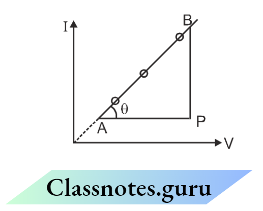
Then a graph is plotted between the potential difference (V) across R and the current (I) through R. The graph comes to be a straight line as shown in the figure.
Result: It is found from the graph that the ratio V/I is constant. Hence, the current voltage relationship is established, i.e., VI.
It means Ohm’s law is established as \(I=\left(\frac{1}{R}\right)\) v, find the slope of the i-v curve and equates it to \(\frac{1}{R} \text {. }\) slope \(=\frac{B P}{A P}=\frac{1}{R}\) Get R=…………..
Solved Examples
Example 58. If the emf of the battery is 100 v, then what was the resistance of Rheostat adjusted at the 2nd reading (I = 2A, V = 20V)?

- 10
- 20
- 30
- 40
Answer: From the curve slope \(=\frac{I}{V}=\frac{1}{R}=\frac{1}{10} \quad R=10 \Omega\) for reading \(I=\frac{E m f}{R+R_{t m}} \quad 2=\frac{100}{10+R_{t h}} \quad \Rightarrow \quad R_m=40 \Omega\)
Measurement and Errors NEET Physics Notes
Example 59. If three wires of the same material but different dimensions were used in place of unknown resistance, we get these I-V curves.

Match the column according to the correct curve:

- (p)-(2); (q)-(3); (r)-(1)
- (p)-(3); (q)-(2); (r)-(1)
- (p)-(1); (q)-(2); (r)-(3)
One of these
Solution: \(R=\frac{\rho \ell}{A}=\frac{\rho \ell}{\pi r^2} \text { for case(p) } R \propto \frac{(1)}{(1)^2} \text { for case (q) } R \propto \frac{(1)}{(2)^2}\)
Example 60. I v/s V curve for a non-ohmic resistance is shown. The dynamic resistance is maximum at point

- a1
- b
- c
- same for all
Solution: Dynamic resistance \(R=\frac{d v}{d I}=\frac{1}{d I / d v}=\frac{1}{\text { slope }}\)
At pt. a slope is min, so R is max
Example 61. If by mistake, the Ammeter is connected parallel to the resistance then the I-V curve expected is (Here I = reading of ammeter, V = reading of voltmeter)

Solution: 3. As the ammeter has very low resistance most of the current will pass through the ammeter so the reading of the ammeter (I) will be very large. The voltmeter has very high resistance so the reading of the voltmeter will be very low.
Example 62. If by mistake, the voltmeter is connected in series with the resistance then the I-V curve expected is (Here I = reading of ammeter, V = reading of voltmeter )

Solution: 4. Due to the voltmeter’s high resistance, the ammeter’s reading will be very low.
⇒ \(\begin{aligned}
& \rho=\frac{R A}{L}=\frac{\pi D^2}{4 L} \frac{V}{I} \\
& \ln \rho=\ln \frac{\pi}{4}+2 \ln D-\ln L+\ln V-\ln I \\
& \frac{d \rho}{\rho}=2 \frac{d D}{D}-\frac{d L}{L}+\frac{d V}{V}-\frac{d I}{I}
\end{aligned}\)
⇒ \(\begin{aligned}
& \frac{\Delta \rho}{\rho}= \pm 2 \frac{\Delta \mathrm{D}}{\mathrm{D}} \mp \frac{\Delta \mathrm{L}}{\mathrm{L}} \pm \frac{\Delta \mathrm{V}}{\mathrm{V}} \mp \frac{\Delta \mathrm{I}}{\mathrm{I}} \\
& \left(\frac{\Delta \rho}{\rho}\right)_{\max }=\max \text { of }\left( \pm 2 \frac{\Delta \mathrm{D}}{\mathrm{D}} \mp \frac{\Delta \mathrm{L}}{\mathrm{L}} \pm \frac{\Delta \mathrm{V}}{\mathrm{V}} \mp \frac{\Delta \mathrm{I}}{\mathrm{I}}\right)
\end{aligned}\)
⇒ \(\left(\frac{\Delta \rho}{\rho}\right)_{\max }=+2 \frac{\Delta \mathrm{D}}{\mathrm{D}}+\frac{\Delta \mathrm{L}}{\mathrm{L}}+\frac{\Delta \mathrm{V}}{\mathrm{V}}+\frac{\Delta \mathrm{I}}{\mathrm{I}}=\text { max. permissible error in } \rho \text {. }\)
Solved Examples
Example 63. In Ohm’s experiment, when a potential difference of 10.0 V is applied, the current measured is 1.00 A. If the length of the wire is found to be 10.0 cm, and the diameter of the wire is 2.50 mm, then the maximum permissible error in resistivity will be
- 1.8%
- 10.2%
- 3.8%
- 5.75%
Answer: \(\left(\frac{\Delta \rho}{\rho}\right)_{\max }=2\left(\frac{0.01}{2.50}\right)+\left(\frac{0.1}{10.0}\right)+\left(\frac{0.1}{10.0}\right)+\left(\frac{0.01}{1.00}\right)=3.8 \%\)
Question 64. If the % error in length, diameter, current, and voltage are the same then which of the following effects % error in measurement of resistivity, the most:
- Length Measurement
- Voltage Measurement
- Current Measurement
- Diameter Measurement
Answer: \(\left(\frac{\Delta \rho}{\rho}\right)_{\max }\)
Question 65. From some instruments, the current measured is I = 10.0 Amp., the potential difference measured is V = 100.0 V, the length of the wire is 31.4 cm, and the diameter of the wire is 2.00 mm (all in the correct significant figure). The resistivity of wire(in correct significant figure) will be – (use π = 3.14 )Ω
- 1.00×10⁻⁴ Ω-m
- 1.00×10⁻⁴ Ω-m
- 1.00×10⁻⁴ Ω-m
- 1.00×10⁻⁴ Ω-m
Answer: \(\rho=\frac{\pi D^2}{4 L} \frac{V}{I}=\frac{(3.14)\left(2.00 \times 10^{-3}\right)^2}{4(0.314)}\left(\frac{100.0}{10.0}\right)\)
Question 66. In the previous question, the maximum permissible error in resistivity and resistance measurement will be (respectively
- 2.14%
- 1.5%
- 1.5%,2.5%
- 2.41%,1.1%
- None Of These
Solution: \(\left(\frac{\Delta R}{R}\right)_{\max }=\frac{\Delta i}{i}+\frac{\Delta v}{v}=\frac{0.1}{10.0}+\frac{0.1}{100.0}=1.1 \%\)
⇒ \(\left(\frac{d \rho}{\rho}\right)_{\max }=2.42 \%\)
Experiment 8
Meter Bridge
The meter bridge is a simple case of Wheatstone-Bridge and is used to find the unknown Resistance. The unknown resistance is placed in place of R, and in place of S, a known resistance is used, u (Resistance Box).
There is a 1m long resistance wire between A and C. The jockey is moved along the wire. When R(100 – l) = S(l) then the Bridge will be balanced, and the galvanometer will give zero deflection. “l” can be measured by the meter scale.
The unknown resistance is \(R=S \frac{\ell}{100-\ell}\)
If the length of the unknown wire is L and the diameter of the wire is d, then the specific resistance of the wire
⇒ \(\rho=\frac{R\left(\frac{\pi d^2}{4}\right)}{L} \quad \text { from eq.(1) } \quad \rho=\frac{\pi d^2}{4 L}\left(\frac{(\ell)}{100-\ell}\right) S\)

Solved Examples
Example 67. If resistance S in RB = 300Ω, then the balanced length is found to be 25.0 cm from end A. The diameter of the unknown wire is 1mm and the length of the unknown wire is 31.4 cm. The specific resistivity of the wire should be
- 2.5 × 10⁻⁴ Ω-m
- 3.5 × 10⁻⁴ Ω-m
- 4.5 × 10⁻⁴ Ω-m
- None Of These
Solution: 1. 2.5 × 10⁻⁴ Ω-m
⇒ \(\frac{R}{300}=\frac{25}{75} \Rightarrow R=100 \Rightarrow \rho=\frac{R \pi d^2}{4 L}=2.5 \times 10^{-4} \Omega-m\)
Example 68. In the previous question. If R and S are interchanged, the balanced point is shifted by
- 30 cm
- 40 cm
- 50 cm
- None of these
Solution : If R and S wave interchanged , l= 75 , 100 – l = 25 Balance point will be shifted by 75 – 25 = 50 cm
Question 69. In a meter bridge, the null point is at l = 33.7 cm, when the resistance S is shunted by 12Ω resistance the null point is found to be shifted by a distance of 18.2 cm. The value of unknown resistance R should be
- 13.5 Ω
- 68.8Ω
- 3.42Ω
- None Of these
Solution: 2. 68.8Ω
⇒ \(\frac{R}{S}=\frac{33.7}{100-33.7} \Rightarrow \frac{R}{\left(\frac{12 \times S}{12+S}\right)}=\frac{(33.7+18.2)}{100-(33.7+18.2)}\) solving get R = 6.86Ω
End Corrections
In the meter Bridge circuit, some extra length comes (is found under metallic strips) at endpoints A and C. So some additional length (α and β) should be included at the ends for accurate results.
Hence in place of we use α + β and in place of 100 – l, we use 100 – l + α (where α and β are called end correction). To estimate α and β, we use known resistance R1 and R2 at the place of R and S in the meter Bridge.
Suppose we get a null point at l1 distance then
⇒ \(\frac{R_1}{R_2}=\frac{\ell_1+\alpha}{100-\ell_1+\beta}\)
Now we interchange the position of R1 and R2 and get a null point at l2 distance then
⇒ \(\frac{R_2}{R_1}=\frac{\ell_2+\alpha}{100-\ell_2+\beta}\)
Solving equation (1) and (2) get
⇒ \(\alpha=\frac{R_2 \ell_1-R_1 \ell_2}{R_1-R_2} \text { and } \beta=\frac{R_1 \ell_1-R_2 \ell_2}{R_1-R_2}-100\)
These end corrections (α and β) are used to modify the observations
Solved Examples
Example 70. If we used 100Ω and 200Ω resistance in place of R and S, we get null deflection at l1 = 33.0cm. If we interchange the Resistance, the null deflection was found to be at l2 = 67.0 cm. The end correction α and β should be:
- α = 1cm, β = 1cm
- α = 2cm, β = 1cm
- α = 1cm, β = 2cm
- None of these
Answer: \(\alpha=\frac{R_2 \ell_1-R_1 \ell_2}{R_1-R_2}=\frac{(200)(33)-(100)(67)}{100-200}=1 \mathrm{~cm}\)
Question 71. Now we start taking observations. At the position of R, unknown resistance is used, and at the position of S, 300Ω resistance is used. If the balanced length was found to be l = 26cm, estimate the unknown resistance.
- 108Ω
- 105.4Ω
- 100Ω
- 110Ω
Answer: \(\frac{\ell_{\text {eq }}}{(100-\ell)_{\text {e- }}}=\frac{R}{300}\)
⇒ \(\begin{aligned}
& \frac{R}{(300)}=\frac{26+1}{(100-26)+1}=\frac{27}{75} \\
& R=\frac{300 \times 27}{75}=108 \Omega .
\end{aligned}\)
Question 72. If the unknown Resistance calculated without using the end correction, is R1 and with using the end corrections is R 2 then (assume same end correction) (1) R1 > R2 when the balanced point is in the first half (2*) R1 < R2 when the balanced point is in first half (3*) R1 > R2 when the balanced point is in the second half(4) R1 > R2 always
Solution:
⇒ \(\mathrm{R}_1=\mathrm{S}\left(\frac{\ell}{100-\ell}\right), \quad \mathrm{R}_2=\mathrm{S}\left(\frac{\ell+\alpha}{100-\ell+\beta}\right)\)
If Balnce points in the first half says i= 40
⇒ \(R_1=S\left(\frac{40}{60}\right) \quad R_2=S\left(\frac{41}{61}\right) \quad \text { so } R_2>R_1\)
if the balance point is in the second half say I = 70
Solution: \(\mathrm{R}_1=\mathrm{S}\left(\frac{\ell}{100-\ell}\right), \quad \mathrm{R}_2=\mathrm{S}\left(\frac{\ell+\alpha}{100-\ell+\beta}\right)\)
if the balance point is in the first half say I= 40
⇒ \(R_1=S\left(\frac{40}{60}\right) \quad R_2=S\left(\frac{41}{61}\right) \quad \text { so } R_2>R_1\)
⇒ \(R_1=S\left(\frac{40}{60}\right) \quad R_2=S\left(\frac{41}{61}\right) \quad \text { so } R_2>R_1\)
If the Balance point is in the second half say i= 70
⇒ \(R_1=S\left(\frac{70}{30}\right) \quad R_2=S\left(\frac{71}{31}\right) \quad \text { so } R_2<R_1\)
Maximum Permissible Error in p:
The specific resistivity of wire, from meter bridge is \(\rho=\frac{\pi \mathrm{D}^{-S}}{4 \mathrm{~L}} \frac{\ell}{100-\ell}\)
Assume that known resistance in RB(S), and the total length of wire is precisely known, then let’s find the maximum permissible error due to an error in measurement of (balance length) and D (diameter of wire).
⇒\(\ln \rho=\ln \left(\frac{\pi S}{4 L}\right)+2 \ln \mathrm{D}+\ln \ell-\ln (100-\ell) \quad \text { (assume there is no error in } \mathrm{S} \text { and } \mathrm{L} \text { ) }\)
⇒ \(\frac{\mathrm{d} \rho}{\rho}=2 \frac{\mathrm{dD}}{\mathrm{D}}+\frac{\mathrm{d} \ell}{\ell}-\frac{\mathrm{d}(100-\ell)}{(100-\ell)}=2 \frac{\mathrm{dD}}{\mathrm{D}}+\frac{\mathrm{d} \ell}{\ell}+\frac{\mathrm{d} \ell}{100-\ell}\)
⇒ \(\left(\frac{\Delta \rho}{\rho}\right)_{\max }=2 \frac{\Delta \mathrm{D}}{\mathrm{D}}+\frac{\Delta \ell}{\ell}+\frac{\Delta \ell}{100-\ell}\)
⇒ \(\left(\frac{\Delta \rho}{\rho}\right)_{\max } \text { due to error in } \ell \text { only is }=\frac{\Delta \ell}{\ell}+\frac{\Delta \ell}{100-\ell}=\frac{\Delta \ell(100)}{\ell(100-\ell)}\)
⇒ \(\left(\frac{\Delta \rho}{\rho}\right)_{\max } \text { will be least when } \ell(100-\ell) \text { is maximum, i.e. } \ell=50 \mathrm{~cm}\)
So % error in resistance (resistivity) will be minimal if the balance point is at the midpoint of the meter bridge wire.
Experiment 9
Post Office Box

In a wheat stone’s Bridge circuit \(\text { If } \frac{P}{Q}=\frac{R}{X}\) then the bridge is balanced. So unknown resistance \(X=\frac{Q}{P} R=\frac{R}{(P / Q)}\) To realize the wheat stone’s Bridge circuit, a pox office Box is described. Resistance P and Q are set in arms AB and BC where we can have 10Ω, 100 Ω, or 1000 Ω resistance to set any ratio \(\frac{P}{Q}.\)
These arms are called ratio arms. Initially, we take Q = 10Ω and P = 10Ω to set \(\frac{P}{Q}=1\) The unknown resistance (X) is connected between C and D, and the battery is connected across A and C (Just like wheat stone’s Bridge).
Now put Resistance in parts A to D such that the Bridge gets balanced. For this keep on increasing the resistance with 1Ω intervals, and check the deflection in the Galvanometer by first pressing key K1 key then the Galvanometer key K2.
Suppose at R = 4Ω, we get deflection toward left and at R = 5Ω, we get deflection toward right. So we can say that for bridge balance. R should be between 4 to 5.
Now x \(X=\frac{R}{(P / Q)}=\frac{R}{(10 / 10)}\) = R=4 to 5
So we can estimate that X should be between 4Ω and 5Ω.
To get closer to X, in the second observation, let’s choose \(\frac{P}{Q}=10 \text { e.i. }\left(\frac{P=100}{Q=10}\right) \text {. }\)
Suppose Now at R = 42. We are getting deflection toward the left, and at R = 43, deflection is toward the right. So Re (42,43).
Now, \(X=\frac{R}{(P / Q)}=\frac{R}{(100 / 10)}=\frac{1}{10} R \text { where } R \in(42,43)\)
So we can estimate that X e (4.2, 4.3). Now to get further closer, choose \(\frac{P}{Q}=100\) As we increase the \(\frac{P}{Q}\) ratio, R will be divided by a greater number, so the answer will be upto more decimal places so answer will be more accurate.
The Observation Table is shown below.

Solved Examples
Examples 73. If the length of the wire is (100.0 cm), and the radius of the wire, as measured from the screw gauge is (1.00 mm) then the specific resistance of the wire material is
- 13.35×10⁻⁶ Ω-m
- 13.4 × 10⁻⁶ Ω-m
- 13.352 × 10⁻⁶ Ω-m
- 16.5 × 10⁻⁶Ω-m
Solution: 2. 13.4 × 10⁻⁶ Ω-m
From observation table R = 4.25Ω
⇒ \(\rho=\frac{(R) \pi r^2}{\ell} \quad=\frac{4.25 \times 3.14 \times(1.00)^2 \times 10^{-6}}{\left(100.0 \times 10^{-2}\right)}\)
= 13.3×10⁻⁵Ω-m
Examples 74. Assertion: To locate null deflection, the battery key (K1) is pressed first and then the galvanometer key (K2). Reason: If first K 2 is pressed, and then as soon as K1 is pressed, the current suddenly tries to increase. so due to self-induction, a large stopping emf is generated in the galvanometer, which may damage the galvanometer.
- If both Assertion and Reason are true and the Reason is a correct explanation of Assertion.
- If both Assertion and Reason and true but Reason is not a correct explanation of
Assertion. - If Assertion is true but Reason is false.
- If both Assertion and Reason are false.
Answer: 1. If both Assertion and Reason are true and the Reason is a correct explanation of Assertion.
Example 75. What is the maximum and minimum possible resistance, which can be determined using the PO Box shown above figure-2
- 1111 kΩ, 0.1 Ω
- 1111 kΩ, 0.01Ω
- 1111 kΩ, 0.001Ω
- None of these
Answer: 2. 1111 kΩ , 0.01Ω
Solution: \(X=\frac{Q}{P} R \quad \Rightarrow \quad(X)_{\max }=\frac{(Q)_{\max }}{(P)_{\min }}(R)_{\max }=\frac{1000}{10}(11110)=1111 \mathrm{k} \Omega\)
\((X)_{\min }=\frac{(Q)_{\min }}{(P)_{\max }}(R)_{\min }=\frac{10}{1000} \frac{10}{1000}(1)=0.01 \Omega\)
Example 76. In a certain experiment, if \(\frac{Q}{P}=\frac{1}{10}\) if 192Ωif used we are getting deflection toward right, at 193 Ω, again toward right but at 194 Ω, deflection is toward left. the unknown resistance should lie between
- 19.2 to 19.3 Ω
- 139. to 19.4 Ω
- 19 to 20Ω
- 19.4 to 19.5Ω
Answer: 2. 139. to 19.4 Ω
Solution: \(X=\frac{Q}{P}(R) \frac{1}{10}=(193 \leftrightarrow 194)=19.3 \leftrightarrow 19.4\)
⇒ \(X=\frac{Q}{P}(R) \frac{1}{10}=(193 \leftrightarrow 194)=19.3 \leftrightarrow 19.4\)
Example 77. If By mistake, Battery is connected between B and C Galvanometer is connected across A and C then
- We cannot get a balanced point.
- The experiment will be less accurate
- Experiments can be done similarly.
- The experiment can be done similarly but now, K2 should be pressed first, then K1.
Answer: 4. Experiment can be done similarly but now, K2 should be pressed first, then K1.
Experiment 10
To Find the Focal Length Of A Concave Mirror Using the U-V Method
Principle: For different u, we measure different v, and find f using mirror’s formula \(\frac{1}{f}=\frac{1}{v}+\frac{1}{u}\)
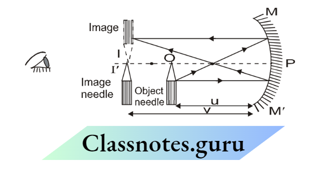
In this experiment, a concave mirror is fixed at position MM’ and a knitting needle is used as an object, mounted in front of the concave mirror. This needle is called an object needle (O in Fig)
First of all, we make a rough estimation of f. For estimating f roughly, make a sharp image of a faraway object (like the sun) on filter paper. The image distance of the far object will be an approximate estimation of focal length).
Now, the object needle is kept beyond f, so that its real and inverted image can be formed. You can see this inverted image in the mirror by closing one eye and keeping the other eye along the pole of the mirror.
To locate the position of the image, use a second needle, and shift this needle such that its peak coincides with the image. The second needle gives the distance of image (v), so it is called the “image needle”.
Note the object distance ‘u’ and image distance ‘v’ from the mm scale on the optical bench and find the focus distance from that Similarly take 4-5 more observations.
Determining ‘f’ from u – v observation:
Using Mirror Formula
Use mirror formula \(\frac{1}{f}=\frac{1}{v}+\frac{1}{u}\) to find the focal length from each u – v observation. Finally, take an average of all.
From \(\frac{1}{\mathrm{v}} \mathrm{v} / \mathrm{s} \frac{1}{\mathrm{u}}\)
⇒ \(\frac{1}{v}+\frac{1}{u}=\frac{1}{f} \Rightarrow \frac{1 / u}{1 / f}+\frac{1 / v}{1 / f}=1 \leftrightarrow \frac{x}{a}+\frac{y}{b}=1\)
So curve between \(\frac{1}{v} \mathrm{v} / \mathrm{s} \frac{1}{\mathrm{u}}\)
should be a straight line having x and y intercepts \(=\frac{1}{f} \text { and } \frac{1}{f}\) from the observations of u and v, plot \(\frac{1}{v} \text { v/s } \frac{1}{u}\) curve as a straight line, find the x and y intercepts and equate them to \(\frac{1}{f} \text { and } \frac{1}{f} \text {. }\)


From u – v curve:
The relation between u and v is
⇒ \(\frac{1}{v}+\frac{1}{u}=\frac{1}{f}\)
So curve between v v/s u is a rectangular hyperbola as shown in the figure. If we draw a line bisecting both the axis, i.e. line
u=v… 2
Graph of v vs. u for a Concave Mirror

Then their intersection points should be v = 2f, u = 2f (By solving equation (1) and equation (2)) from u – v data, plot v v/s u curve, and draw a line bisecting the axis. Find the intersection points and equate them to (2f, 2f).

From the intersection of lines joining u n and vn:
Indicate u1, u2, u3 ……. un on x-axis, and v1, v2, v3 …….. vn on y-axis. If we join u 1 with v1, u2, u3 with v3 and …………… so on. All line intersects at a common point (f, f).
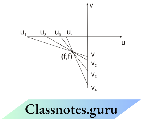
Explanation
Line joining u1 and v1 is
⇒ \(\begin{aligned}
& \frac{x}{u_1}+\frac{y}{v_1}=1 \\
& \frac{1}{u_1}+\frac{1}{v_1}=\frac{1}{f} \text { or } \frac{f}{u_1}+\frac{f}{v_1}=1
\end{aligned}\) ………(1)
Line joining u2 and v2 is
Where \(\begin{aligned}
& \frac{x}{u_2}+\frac{y}{v_2}=1 \\
& \frac{f}{u_2}+\frac{f}{v_2}=1
\end{aligned}\)
Similarly, line joining un and vn is
⇒ \(\begin{aligned}
& \frac{\mathrm{x}}{\mathrm{v}_{\mathrm{n}}}+\frac{\mathrm{y}}{\mathrm{u}_{\mathrm{n}}}=1 \\
& \frac{f}{u_n}+\frac{f}{v_n}=1
\end{aligned}\)
From equation (1’), (2’), (3’), we can say that x = f and y = f will satisfy all equations (1), (2), (3). So point (f, f) will be the common intersection point of all the lines.
From u – v data draw u 1, u2 …… un on the x-axis and v1, v1, …….. vn data on the y-axis. Join u 1 with v1, u2 with v2 …….. un with vn. Find a common intersection point and equate it to (f, f).

Index Error
In the u – v method, we require the distance between the object or image from the pole (vertex) of the mirror (actual distance).
But practically we measure the distance between the indices A and B. (Observed distance), which need not exactly coincide with the object and pole, there can be a slight mismatch called index error, which will be constant for every observation.

Index error = Observed distance – Actual distance (Just like zero error in screw gauge, it is the excess reading).
To determine index error, the mirror and object needle are placed at arbitrary positions. For measuring actual distance, a knitting needle is just fitted between the pole of the mirror and object needle “O”.
The length of the knitting needle will give the actual object distance while the separation between indices A and B at that instant is the observed distance.
So index error is e = Observed distance – Actual distance = Separation between indices A and B – Length of knitting needle once we get e, in every observation, we get Actual distance = Observed distance (separation between the indices) – Excess reading (e) There is another term, Index correction which is inverse of index error. Index correction = – index error.
Class 12 NEET Physics Measurement Errors and Experiments Summary
Example 78. To find index error for u, when a knitting needle of length 20.0 cm is adjusted between pole and object needle, the separation between the indices of object needle and mirror was observed to be 20.2 cm. Index correction for u is –
- –0.2 cm
- 0.2 cm
- –0.1 cm
- 0.1 cm
Solution: (2) Index error (Excess reading) = Observed reading – Actual reading = 20.2 – 20.0 = 0.2 cm
Example 79. To find the index error for v, when the same knitting needle is adjusted between the pole and the image needle, the separation between the indices of the image needle and mirror was found to be 19.9 cm. The index error for v is
- 0.1 cm
- –0.1 cm
- 0.2 cm
- –0.2 cm
Solution : (2) e = 19.9 cm – 20.0 cm = –0.1 cm
Example 80. In some observations, the observed object distance (Separation between indices of object needle and mirror) is 30.2 cm, and the observed image distance is 19.9 cm. Using index correction from the previous two questions, estimate the focal length of the concave mirror!
Solution: u = 30.2 – 0.2 (excess reading)
= 30.0 cm.
v = 19.9 – (–0.1) (excess reading)
= 20.0 cm.
⇒ \(\frac{1}{f}=\frac{1}{v}+\frac{1}{u} \Rightarrow f=12.0 \mathrm{~cm} .\)
Maximum permissible error in f due to imperfect measurement of u & v:
In this experiment, from a set (u, v), focus distance f can be calculated from the equation.
⇒ \(\begin{aligned}
& \frac{1}{f}=\frac{1}{u}+\frac{1}{v} \Rightarrow \frac{d f}{f^2}=\frac{d u}{u^2}+\frac{d v}{v^2} \\
& \left(\frac{\Delta f}{f^2}\right)= \pm \frac{\Delta u}{u^2} \pm \frac{\Delta v}{v^2} \Rightarrow\left(\frac{\Delta f}{f^2}\right)_{\max }=+\frac{\Delta u}{u^2}+\frac{\Delta v}{v^2} \Rightarrow(\Delta f)_{\max }=\left(\frac{\Delta u}{u^2}+\frac{\Delta v}{v^2}\right) \times f^2
\end{aligned}\)
Solved Examples
Example 81. In the u – v method to find the focal length of a concave mirror, if the object distance was found to be 10.0 cm and the image distance was also found to be 10.0 cm then find a maximum permissible error in f, due to error in u and v measurement.
Solution: \(\frac{1}{u}+\frac{1}{v}=\frac{1}{f} \Rightarrow \quad \frac{1}{(-10)}+\frac{1}{(-10)}=\frac{1}{f} \Rightarrow|f|=5 \mathrm{~cm}\)
⇒ \((\Delta f)_{\max }=\left(\frac{\Delta u}{u^2}+\frac{\Delta v}{v^2}\right) \times f^2\) \((\Delta \mathrm{f})_{\max }=\left(\frac{0.1}{10^2}+\frac{0.1}{10^2}\right) \times 5^2=0.05 \mathrm{~cm}\)
So, f = (5 ± 0.05) cm
Experiment 11
To find the focal length of a convex lens using the u-v method.
Principle: For different u, we measure different v, and find f using lens’s formula \(\frac{1}{f}=\frac{1}{v}-\frac{1}{u}\)
Procedure: In this experiment, a convex lens is fixed at position L and a knitting needle is used as an object, mounted in front of the concave mirror. This needle is called object needle.
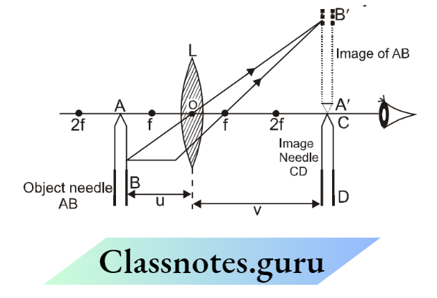
First of all, we make a rough estimation of f. For estimating f roughly, make a sharp image of a faraway object (like the sun) on filter paper. The image distance of the far object will be an approximate estimation of focal length. Now, the object needle is kept beyond f, so that its real and inverted image (I in Fig) can be formed.
To locate the position of the image, use a second needle, and shift this needle such that its peak coincides with the image. The second needle gives the distance of image (v), so it is called the “image needle” (CD in figure). Note the object distance ‘u’ and image distance ‘v’ from the mm scale on an optical bench.
Similarly take 4-5 more observations.
Determining ‘f’ from u – v observation:
Using lens Formula:
Use lens formula \(\frac{1}{f}=\frac{1}{v}-\frac{1}{u}\) to find the focal length from each u – v observation. Finally, take an average of all.
For \(\frac{1}{v} v / s \frac{1}{u}\) curve:
⇒ \(\frac{1}{v}-\frac{1}{u}=\frac{1}{f} \Rightarrow \frac{1 / u}{-1 / f}+\frac{1 / v}{1 / f}=1 \leftrightarrow{ }^{\frac{x}{a}}+\frac{y}{b}=1\)
So curve between \(\frac{1}{v} \mathrm{v} / \mathrm{s} \frac{1}{u}\) should be a straight line having x and y intercepts \(=\frac{1}{f}-\frac{1}{f}\) and

Graph of \(\frac{1}{v} \text { vs. } \frac{1}{u}\) for a convex lens from the observations of u and v, plot \(\frac{1}{v} v / s \frac{1}{u}\) curve as a straight line, find the x and y intercepts and equate them to \(-\frac{1}{f} \text { and } \frac{1}{f} \text {. }\)

From u – v curve:
Relation between u and v is \(\frac{1}{v}-\frac{1}{u}=\frac{1}{f}\)……(1)
Then their intersection points should be V = 2f, u = – 2f (By solving equation (1) and equation (2)) from u – v data, plot v v/s u curve, and draw a line y = -x. Find the intersection points and equate them to (-2f, 2f).
Graph of v vs. u for a Convex lens

From the intersection of lines joining u n and vn:
Indicate u1, u2, u3 ……. un on x-axis, and v1, v2, v3 …….. vn on y-axis. If we join u 1 with v1, u2 with v2, u3 with v3 and …………… so on. All line intersects at a common point (-f, f).

From u – v data draw u1, u2 …… un on the x-axis and v1, v2, …….. vn data on the y-axis. Join u1 and v1, u2 with v2 …….. un and vn. Find a common intersection point and equate it to (-f, f)
Index error and max permissible error are similar to the concave mirror.
Experiment 12
Object: To study the dissipation of energy of a simple pendulum by plotting a graph between the square of amplitude and time.
Apparatus: Ticker timer, paper tape, meter scale, thread, clamp, metallic brick as bob, clamps, split cork, and a spring balance.
Principle: The energy of a simple harmonic oscillator is directly proportional to its amplitude. When the bob of a simple pendulum is set into vibrations, its amplitude goes on decreasing with time due to friction of air and friction at the point of support.
Such vibrations whose amplitude decreases with time due to some dissipative force are called damped vibrations. The vibrations of a simple pendulum are also damped. At any time t the energy Et = E. e–λt, where λ is the decay constant and energy E is given by E =1/2 KA2 where A is the amplitude and K is force constant.

Method
- Find the mass of the metallic brick by the spring balance.
- Fix the clamp stand on the edge of the table with the help of clamps.
- One end of the thread with the metallic brick and pass the other end of the thread through the split cork hold the cork in the clamp stand.
- Fix the ticker timer at the same height above the ground on the brick is attach the paper tape at the center of the brick with the help of the cello tape.
- Full the brick towards the ticker timer and take the paper tape. Start the ticker timer and release the brick.
- As the brick reaches the outer extreme switch off the ticker timer.
- Remove the paper tape. The pattern of dots obtained on the tape will be as shown below.
- Mark the central dot A and the extreme dots B and C corresponding to the extreme positions of the metallic brick.
- Measure the distance of the dots from the central dot A

Observations:
- Least count of spring balance = …………. kg
- Corrected mass of the metallic block = m = …………. kg
- Period of ticker-timer (one tick) = ………….. sec
- Length of simple pendulum, = L = …………… m

Graph

From the graph, it is clear that Energy (Amp)2 and the energy of the pendulum decrease with time.
Precaution
- An inextensible string thread should be used for making the pendulum.
- The lower faces of the split cork should lie in the same horizontal plane.
- The amplitude of oscillation should be kept small.
- The experiment should be performed at a place which is free from any air disturbance.
- The metallic brick should be suspended close to the ground.
- The metallic brick should move along the reference line without any jerky motion.
Result
The sum of the kinetic energy and potential energy of the bob (metallic block) of the simple pendulum is constant within the limits of the experimental error. This shows that the energy is being transferred from kinetic to potential and vice versa. From the above graph, it is proved that there is dissipation of energy during SHM of a simple pendulum.
Precaution
- Pendulum support should be rigid
- The amplitude should remain small.
- The pendulum should be sufficiently long (about 2 meters).
- Pulling string should be used to avoid spinning the metallic block
- Paper tape should be attached to the center of the bottom of the block.
Source of Error
- The support may not be fully rigid.
- Movement of metallic block may not be proper
Experiment 13
Object: To determine the mass of a given body using a meter scale by the principle of moments
Apparatus: A meter scale, a broad heavy wedge with a sharp edge, a weight box, a body of unknown mass
Principle
Meter scale as a beam balance: –
Introduction: Like a physical balance, a meter scale can be used as a beam balance making use of the same principle of moments. Besides it has an adjustable power arm and weight arm about the fulcrum whose length can be adjusted.
Diagram:

Construction (Arrangement): The meter scale is balanced by putting its 50 cm mark over the sharp edge of a heavy broad wedge works as a fulcrum. In this position, the weight of the meter scale and the reaction of the wedge, balance each other.
Working: The body is tied to a strong and light thread loop and suspended on the left of the wedge on some fixed mark. (Say 20 cm in diagram)
A light paper pan is suspended by a strong and light thread on the right. Weights are put on the pan. The position of the loop of the pan and weight in it are so adjusted that the meter scale becomes horizontal again. The position of the thread of the loops and the amount of weights in the pan are noted.
The mass of the body is calculated using the following theory.
Theory: If m and M are the mass of the body and mass of the weight used and a1 and a2 are the distance of their loops from the wedge. Then, power (mass) arm = a1, weight arm = a2 or \(m=\frac{M a_2}{a_1}\)
Two different methods:
Arm lengths are fixed and equal and weight is adjustable.
The thread loops are suspended at position forming both arms of equal length. Weight in the paper pan is adjusted till the meter scale becomes horizontal. (figure (a)) In this case a1 = a2 = a Hence, mga1 = Mga2 or m=M
A physical balance makes use of this method.
Masses and power arm fixed and weight arm adjustable.
Mass is suspended at a fixed distance a1.
The length of the power arm is adjusted by moving the weight loop thread in and out till the meter scale becomes horizontal
In this case a
1 = a1, a2 =A
Hence mga1 = Mga2, becomes mg a= MgA Or \mathrm{m}=\mathrm{M} \frac{\mathrm{A}}{\mathrm{a}}\(\)
Procedure
First method
- Arrange the meter scale horizontally by supporting it at the sharp edge of the broad heavy wedge at the 50 cm mark.
- Suspend the body of unknown mass by a loop thread at a fixed mark on the left of the wedge.
- Suspended paper pan at the same distance on the right of the wedge with some weights in it.
- Adjust the weights in a paper pan till the meter scale becomes horizontal.
- Note the mass of the weights in the pan.
- Repeat steps 2 to 5, three times by increasing the length of the arms in equal steps keeping the lengths equal.
- Record the observations as given below in a table.
Observation And Calculations

Note: Observations are as sample
Mean mass, \(\mathrm{m}=\frac{\mathrm{m}_1+\mathrm{m}_2+\mathrm{m}_3}{3} \mathrm{~g}=\ldots . . \mathrm{g}\)
It will be found that M1 = M2 = M3 = m in all cases.
Result
The unknown mass of the body, m = 20 g
Second method
- 1,2. Steps 1 and 2 of the first method.
- Suspend the paper pan on the right of the wedge with some known weight in it.
- Adjust the distance of the paper pan till the meter scale becomes horizontal.
- Note the position of the paper pan and thus length of the weight arm.
- Repeat steps 2 to 5, three times by increasing the mass of the weights by an equal amount.
- Record the observations as given below in the table.
Observation And Calculations
Fixed length of power arm = a= 25 cm

(Note: Observations are as sample)
Mean mass, \(\mathrm{m}=\frac{\mathrm{m}_1+\mathrm{m}_2+\mathrm{m}_3}{3} \mathrm{~g}=\ldots . \mathrm{g}\)
It will be found that \(\mathrm{m}_1=\mathrm{m}_2=\mathrm{m}_3=\mathrm{m} \text { in all cases. }\)
Result
The unknown mass of the body, m = 24 g
Precautions:
- The wedge should be broad and heavy with a sharp edge.
- The meter scale should have uniform mass distribution.
- Threads used for loops should be thin, light, and strong.
Sources Of Error
- The wedge may not be sharp.
- The meter scale may have faulty calibration.
- The threads used for loops may be thick and heavy.
NEET Physics Chapter 2 Notes: Measurement Errors and Experiments
Experiment 14
Aim
To determine the surface tension of water by capillary rise method.
Apparatus
Three capillary tubes of different radii and a tipped pointer clamped in a metallic plate with a handle, traveling microscope, clamp and stand, a fine motion adjustable height stand, a flat bottom open dish, clean water in a beaker, and thermometer.
Theory
Rise of liquid level in a capillary tube (Ascent formula):
Let a capillary tube be dipped in a liquid which makes a concave meniscus in the tube. Due to surface tension, the tube molecules exert a force T on the liquid molecules in the unit length of the circle of contact of the liquid surface with the tube. This force acts at an angleθ (angle of contact) with the wall of the vessel.
Components T sinθ perpendicular to the wall of the tube cancel for the whole circle. Component T cosθ along the wall of the tube on all molecules becomes 2πrT cosθ. It is this upward force that pulls the liquid upward in the capillary tube.
The liquid rises in the capillary tube upto a height till the weight of the liquid rises equals this force. Let the liquid rise upto a height of h (as measured for the lower meniscus B) and let the meniscus ABC have a hemispherical shape.
The volume of liquid in the meniscus above B. Then, the volume of the liquid rises upto the lower meniscus = πr²h. The volume of a cylinder of radius and height r – Volume of hemisphere of radius r.
⇒ \(=\pi r^2 \cdot r-\frac{2}{3} \pi r^3=\frac{1}{3} \pi r^3\)

Total volume of the liquid risen \(=\pi r^2 h+\frac{1}{3} \pi r^3=\pi r^2\left[h+\frac{r}{3}\right]\)
If liquid has a density p, then mass of liquid risen \(=\pi r^2=\left[h+\frac{r}{3}\right] \rho\) and weight of the liquid risen \(=\pi r^2\left[h+\frac{r}{3}\right] \rho g\) and weight of the liquid risen \(=\pi r^2\left[h+\frac{r}{3}\right] \rho g\) and weight of the liquid risen \(=\pi r^2\left[h+\frac{r}{3}\right] \rho g\) For Equilibrium ‘
⇒ \(\pi r^2\left[h+\frac{r}{3}\right] \rho g=2 \pi r T \cos \theta \quad \text { or } \quad h=\frac{2 T \cos \theta}{r \rho g}-\frac{r}{3}\)
[From above we find that \(h \propto \frac{1}{r},\) liquid rises more in a capillary tube of small radius] Also, \(\mathrm{T}=\frac{(\mathrm{h}+\mathrm{r} / 3) \mathrm{r} \rho \mathrm{g}}{2 \cos \theta}\) Measuring height h of liquid risen in capillary tube and knowing other quantities, surface tension of
liquid (T), can be calculated.
[In practice, r/3 is neglected as compared to h, then \(\mathrm{T}=\frac{\mathrm{hr} \rho \mathrm{g}}{2 \cos \theta}\) ]

A traveling microscope is a device that is used for the accurate measurement of very small distances. It is a compound microscope fixed on a strong metallic horizontal platform that can be balanced with the help of leveling screws L and L’.
The compound microscope can slide or travel both along horizontal and vertical levels. Due to the horizontal or vertical traveling of the microscope, we have named it as a traveling microscope.
The compound microscope consists of two convex lenses called objective O which is placed close to the object and eye-piece E placed near the eye of an observer. Objective O is a simple convex lens small aperture and a small focal length.
These two lenses are placed in two distinct tubes placed coaxially. To focus object the tubes can be moved by using a rack and pinion arrangement R. The microscope has a crosswire in front of the eye-piece which serves as a reference mark. The object to be seen is placed in front of the objective and the image is viewed through the eyepiece. The image formed is virtual, magnified, and inverted.
The distance through which the microscope moves can be read with the help of a vernier scale (V) moves with the microscope along with the scale engraved on the framework. The horizontal movement of the microscope is done with the help of screw P. and the vertical movement of the microscope is done with the help of screw Q whereas the horizontal and vertical shifting for the fine adjustment microscope can be done with the help of fine screws P’ and Q’.

Setting the apparatus
- Place the adjustable height stand on the table and make its base horizontal by leveling screws.
- Take dirt and grease-free water in an open dish with a flat bottom and put it on the top of the stand.
- Take three capillary tubes of different radii (ranging from 0.05 mm to 0.15 mm)
- Clean and dry them, and clamp the capillary tubes in a metallic plate in order of increasing radius.
- Also, clamp a pointer after the third capillary tube.
- Clamp the horizontal handle of the metallic plate in a vertical stand, so the capillary tubes and the pointer become vertical.
- Adjust the height of the metallic plate so that the capillary tubes dip in water in an open dish.
- Adjust the position of the pointer, such that its tip just touches the water surface.
Measurement of capillary rise
- Find the least count of the traveling microscope for the horizontal and the vertical scale.
- Record the same in the notebook.
- Raise the microscope to a suitable height, keeping its axis horizontal and pointing towards the capillary tubes.
- Bring the microscope in front of the first capillary tube (which has maximum rise).
- Make the horizontal cross wire just touch the central part of the concave meniscus (seen convex through a microscope.
- Note the reading of the position of the microscope on the vertical scale.
- Now move the microscope horizontally and bring it in front of the second capillary tube.
- Lower the microscope and repeat steps 11 and 12.
- Repeat steps 13 and 14 for the third capillary tube.
- Lower the stand so that the pointer tip becomes visible.
- Move the microscope horizontally and bring it in front of the pointer.
- Lower the microscope and make the horizontal cross-wire touch the tip of the pointer. Repeat step 12.
- Measurement of the internal diameter of the capillary tube.
- Place the first capillary tube horizontally on the adjustable stand.
- Focus the microscope on the end dipped in water. A white circle (inner bore) surrounded by a green circular strip (glass cross-section) will be seen.
- Make horizontal cross-wire touch the inner circle at A. Note microscope reading on vertical
scale. - Raise the microscope to make the horizontal cross-wire touch the circle at B. Note the reading (the difference gives the vertical internal diameter AB of the capillary tube).
- Move the microscope on a horizontal scale and make the vertical cross wire touch the inner circle at C. Note the microscope reading on the horizontal scale.
- Move the microscope to the right to make the vertical cross-wire touch the circle at D. Note the reading (the difference gives the horizontal diameter CD of the capillary tube).
- Repeat steps 19 to 24 for the other two capillary tubes.
- Note the temperature of the water in the dish.
- Record your observations as given below.
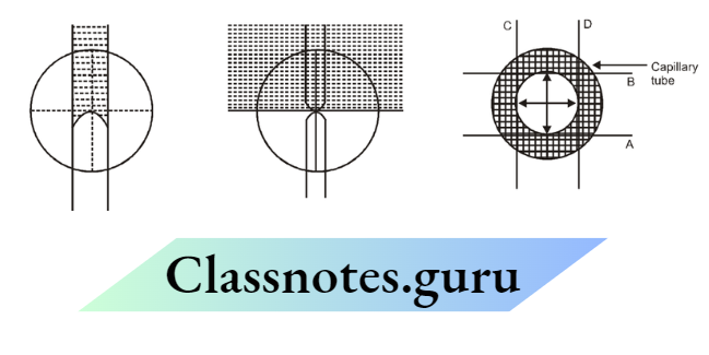
Table for the height of liquid rise

Table for internal diameter of the capillary tube

- The temperature of the water, (t) = …….. ºC
- Density of water at observed temperature, p = …….. (g cm–3)
- The angle of contact of water in a glass, θ = 8º
- i.e., cos θ = 0.99027 taken as 1.
Calculations
From formula, \(\mathrm{T}=\frac{\mathrm{r}(\mathrm{h}+\mathrm{r} / 3) \rho g}{2 \cos \theta}\).
Put values of h (column 4-first table) and r (column 4-second table) for each capillary tube separately and find the value of T (in dynes cm –1).
Find Mean VAlue, \(T=\frac{T_1+T_2+T_3}{3}=\ldots . . . \text { dynes } \mathrm{cm}^{-1}\)
Result
The surface tension of water at tºc = …….dynes cm –1.
Precautions
- The capillary tube and water should be free from grease.
- The capillary tube should be set vertically.
- The microscope should be moved in a lower direction only to avoid backlash errors.
- The internal diameter of the capillary tube should be measured in two mutually perpendicular directions.
- The temperature of the water should be noted.
Sources Of Error:
Water and capillary tubes may not be free from grease.
Experiment 14
Aim: To study the effect of the detergent on surface tension by observing capillary rise.
Apparatus
Three capillary tubes of different radii and a tipped pointer clamped in a metallic plate with a handle, traveling microscope, clamp and stand, a fine motion adjustable height stand, a flat bottom open dish, clean water in a beaker, and thermometer.
Theory
A detergent when added to distilled water reduces the surface tension of water. If we use the same capillary tube to study the rise of pure distilled water and then the rise of detergent mixed water (solution), we shall find that the rise will be lesser in case of solution. If the quantity of detergent (solution concentration) is increased, the rise will be still lesser.
Procedure
- Set the apparatus as in the previous Experiment.
- Find the rise of pure distilled (grease-free) water through the capillary tube following all the steps of the previous Experiment.
- Take a known volume of distilled water from the same sample.
- Dissolve a small known mass of a detergent in the water to make a dilute solution.
- Find the rise of the solution in the same capillary tube. The rise will be less than that for pure water.
- Add double the mass of detergent in the same volume of water to have a solution with double concentration.
- Find the rise of this concentrated solution in the same capillary tube. The rise will be still lesser.
- Repeat with the solution of the same detergent having increased concentration. The rise will decrease as concentration increases.
[Note: Do not make the solution too concentrated to affect density] Observation The rise in capillary tube decreases with the addition of detergent in pure water with more addition of detergent, the rise becomes lesser and lesser.
Result
- The detergent reduces the surface tension of water.
- The capillary tube and water should be free from grease.
- Capillary tube should be set vertically.
- The microscope should be moved in a lower direction only to avoid backlash errors.
- The internal diameter of the capillary tube should be measured in two mutually perpendicular directions.
- The temperature of the water should be noted.
Sources of Error
Water and capillary tubes may not be free from grease.
Experiment 15
AIM: To determine the coefficient of viscosity of a given viscous liquid by measuring the terminal velocity of a given spherical body.
Apparatus: A half-meter high, 5 cm broad glass cylindrical jar with millimeter graduations along its height, transparent viscous liquid, one steel ball, screw gauge, stop clock/watch, thermometer, and clamp withstand.
Theory:
Terminal velocity :
Definition: The maximum velocity acquired by the body, falling freely in a viscous medium, is called terminal velocity.
Expression: Considering a small sphere of radius r of density p falling freely in a viscous medium (liquid) of density p. The forces acting on it are :
The weight of the sphere acting downward \(=\frac{4}{3} \pi r^3 \rho g\)
The effective downward force, \(\mathrm{mg}=\frac{4}{3} \pi r^3 \rho \mathrm{g}-\frac{4}{3} \pi \mathrm{r}^3 \sigma \mathrm{g}=\frac{4}{3} \pi r^3(\rho-\sigma) \mathrm{g}\)
The upward force of viscosity, F = 6pipinrv
When the downward force is balanced by the upward force of viscosity, the body falls with a constant velocity, called terminal velocity. Hence, with terminal velocity,
⇒ \(6 \pi \eta r v=\frac{4}{3} \pi r^3(\rho-\sigma) g\) or terminal velocity
This is the required expression.
Terminal velocity \(=\frac{2}{9} \frac{r^2(\rho-\sigma) g}{\eta} \quad \text { or } \quad \eta=\frac{2}{9} \frac{r^2(\rho-\sigma) g}{v}\)
knowing r, p, and e, and measuring v, n can be calculated.

Procedure:
- Clean the glass jar and fill it with the viscous liquid, which must be transparent.
- Check that the vertical scale along the height of the jar is visible. Note it’s the least count.
- Test the stop clock/watch for its tight spring. Find its least count and zero error (if any)
- Find and note the least count and zero error of the screw gauge.
- Determine the mean radius of the ball.
- Drop the ball gently in the liquid. It falls into the liquid with accelerated velocity for about one-third of the height. Then it falls with uniform terminal velocity.
- Start the stop clock/watch when the ball reaches some convenient division (20 cm, 25 cm,…..).
- Stop the stop clock/watch just when the ball reaches the lowest convenient division (45 cm).
- Find and note the distance fallen and the time taken by the ball.
- Repeat steps 6 to 9 two times more.
- Note and record the temperature of the liquid.
- Record your observations as given ahead.
Observations:
Least count of vertical scale =…….mm.
Least count of stop clock/watch =…….s.
Zero error of stop clock/watch =…….s.
Pitch of the screw (p) = 1 mm.
Number of divisions on the circular scale = 100
Least count of screw gauge (L.C.) \(=\frac{1}{100}=0.01 \mathrm{~mm}\)
Zero error of screw gauge (e) =……mm.
Zero correction of screw gauge (C) (– e) =…….mm
Diameter of spherical ball
- Along one direction, D1 = ……..mm
- In the perpendicular direction, D2 = ……..mm
Terminal velocity of spherical ball
- Distance fallen S = …..mm
- Time taken, t1 = …..s
- t2 = …..s
- t3 = …..s
Calculations
Mean Diameter \(D=\frac{D_1+D_2}{2} \mathrm{~mm}\)
Mean radius \(\mathrm{r}=\frac{\mathrm{D}}{2} \mathrm{~mm} \quad=\ldots \ldots \ldots \mathrm{cm}\)
Mean Time \(\mathrm{t}=\frac{\mathrm{t}_1+\mathrm{t}_2+\mathrm{t}_3}{3}=\ldots . . \mathrm{s}\)
Mean Terminal Velocity \(v=\frac{S}{t} \quad=\mathrm{cm} \mathrm{s}^{-1}\)
From formula, \(\eta=\frac{2 r^2(\rho-\sigma) g}{9 v} \text { C.G.S. units. }\)
Result
The coefficient of viscosity of the liquid at temperature (θºC) = …..C.G.S. units
Precautions
- Liquid should be transparent to watch the motion of the ball.
- Balls should be perfectly spherical.
- Velocity should be noted only when it becomes constant.
Sources Of Error
- The liquid may have a uniform density.
- The balls may not be perfectly spherical.
- The noted velocity may not be constant
Experiment 16
AIM: To study the relationship between the temperature of a hot body and time by plotting a cooling curve.
Apparatus
Newton’s law of cooling apparatus (a thin-walled copper calorimeter suspended in a double-walled enclosure) two thermometers, clamp and stand, stop clock/watch.
Theory:
Newton was the first person to investigate the heat lost by a body in the air. He found that the rate of loss of heat is proportional to the excess temperature over the surroundings. This result, called Newton’s law of cooling, is approximately true in still air only for a temperature excess of 20 K or 30 K. Consider a hot body at a temperature T placed in surroundings at temperature T0.
Rate of loss loss of heat \(=-\frac{\mathrm{dQ}}{\mathrm{dt}}\)
Using Newton’s law of cooling \(-\frac{\mathrm{dQ}}{\mathrm{dt}} \propto\left(\mathrm{T}-\mathrm{T}_0\right)\) or \(\frac{d Q}{d t}=-k\left(T-T_0\right)\) where k is constant of proportionality whose value depends upon the area and nature of surface of the body. If the temperature of the body falls by a small amount of dT in time dt, then DQ= mcdT
where m is the mass of the body and c is the specific heat of the material of the body.
Now, \(\mathrm{mc} \frac{\mathrm{dT}}{\mathrm{dt}}=-\mathrm{k}\left(\mathrm{T}-\mathrm{T}_0\right)\)
Or, \(\frac{\mathrm{dT}}{\mathrm{dt}}=-\frac{\mathrm{k}}{\mathrm{mc}}\left(\mathrm{T}-\mathrm{T}_0\right)\) [ he re \(\mathrm{K}=\frac{\mathrm{k}}{\mathrm{mc}}\) =constant]
Again \(\frac{d T}{T-T_0}=-K d t\)
Integrating \(\int \frac{1}{\mathrm{~T}-\mathrm{T}_0} \mathrm{dT}=-\mathrm{K} \int \mathrm{dt}\)

This is the equation of a straight line having a negative slope (– K) and intercept C on the Y-axis, The Figure shows the graph of loge (T – T0) versus time t. While t has been treated as the x-variable, loge (T – T0) has been treated as the y-variable.
If Tm is the maximum temperature of a hot body, then at t = 0 from equation
⇒ \(\begin{aligned}
& \log \left(T_m-T_0\right)=C \\
& \log \left(T-T_0\right)-\log \left(T_m-T_0\right)=-k t \\
& \log \left(\frac{T-T_0}{T_m-T_0}\right)=-k t \quad \Rightarrow \quad \frac{T-T_0}{T_m-T_0}=e^{-k t}
\end{aligned}\)
So, \(\left(T-T_0\right)=\left(T_m-T_0\right) e^{-k t}\)

Procedure
- Fill the space between the double wall of the enclosure with water and put the enclosure on a laboratory table.
- Fill the calorimeter two-thirds with water heated to about 80ºC.
- Suspend the calorimeter inside the enclosure along with a stirrer in it. Cover it with a wooden lid having a hole in its middle.
- Suspend from clamp and stand, one thermometer in enclosure water and the other in calorimeter water.
- Note the least count of the thermometers.
- Set the stop clock/watch at zero and note its least count.
- Note the temperature (T0) of water in the enclosure.
- Start stirring the water in the calorimeter to make it cool uniformly.
- Just when the calorimeter water has some convenient temperature reading (say 70ºC), note it and start the stop clock/watch.
- Continue stirring and note the temperature after every 5 minutes. The temperature falls quickly in the beginning.
- Note enclosure water temperature after every five minutes.
- When the fall of temperature becomes slow note the temperature at intervals of two minutes for 10 minutes and then at intervals of 5 minutes.
- Stop when the fall of temperature becomes very slow.
- Record your observations as given ahead
Observations
- Least count of enclosure water thermometer = …………ºC
- Least count of calorimeter water thermometer = …………ºC
- Least count of stop clock/watch = …………s.
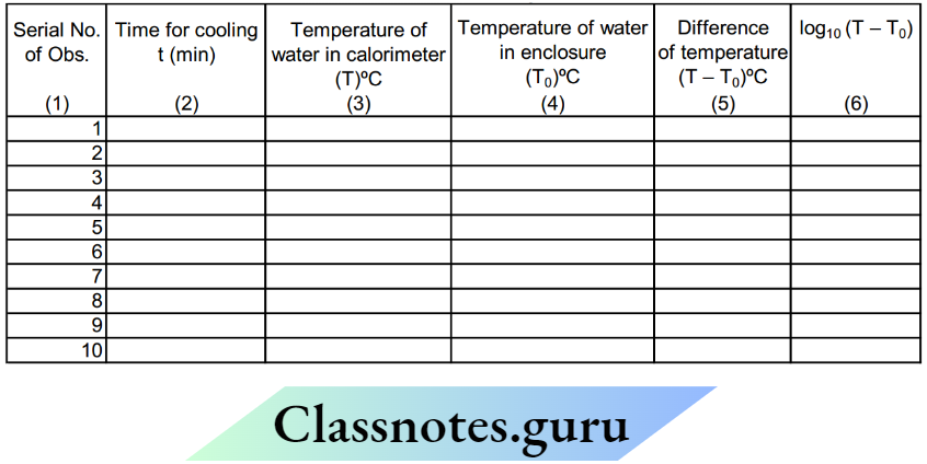
Calculations
- The temperature of water in the enclosure will be found to remain the same. If not then take its mean as T0.
- Find the temperature difference (T – T0) and record it in column 5 of the table.
- Plot a graph between time t (column 2) and temperature T (column 3), taking t along the X-axis and T along the Y-axis. The graph is shown in the given figure. It is called the cooling curve’ of the liquid.
NEET Physics Class 12 Chapter 2 Study Material: Errors and Experiments
The graph between time and temperature (Cooling curve)
Scale:
- X-axis: 1 cm = 5 minutes of t
- Y – axis: 1 cm = 5º C of T

Result
The temperature falls quickly in the beginning and then slowly as the difference in temperature goes on decreasing. This is in agreement with Newton’s law of cooling.
Precautions
The double-walled enclosure should be used to maintain the surroundings at a constant temperature.
Stirring should remain continuous for uniform cooling
- Sources Of Errors Surrounding temperature may change.
- The stirring of hot liquid may not be continuous.
Experiment 17
AIM: To determine the specific heat of a given solid (lead shots) by method of mixtures.
Apparatus
Solid (lead shots), copper calorimeter with a copper stirrer and lid, calorimeter jacket (a wooden box with a coating of insulating material inside), hypsometer, heating arrangement tripod, burner, and wire gauze or a hot plate, two Celsius thermometers graduated in 0.2ºC. Water and a physical balance, weight box, and milligram fractional weights.
Theory
The law of mixtures states that when two substances at different temperatures are mixed, i.e., brought in thermal contact with each other, then the heat is exchanged between them, the substance at a higher temperature loses heat, and that at a lower temperature gains heat. The exchange of heat energy continues till both substances attain a common temperature called equilibrium temperature.
The amount of heat energy lost by the hotter body is equal to the amount of heat energy gained by the colder body, provided
No heat is lost to the surroundings and The substances mixed do not react chemically to produce or absorb heat.
In brief, the law mixtures is written as: On mixing of two substances at different temperatures, if no heat is lost to surroundings; at the equilibrium temperature, Heat gained = Heat lost For a body of mass m, and specific heats, when its temperature falls by Δ, the amount of heat lost by it is given as ΔQ = m.s Δ The same formula is used for the amount of heat gained by colder body where Δ0, would be the temperature rise.
Specific Heat
Specific heat of a substance is the amount of heat required to raise the temperature of the unit mass of the substance through one degree Celsius. S.I. unit of specific heat is J kg –1 K–1. A convenient measure of mass in the lab is gram and temperature is ºC. so we express specific heat as J g –1 ºC–1.

Procedure
- To ensure that two thermometers read the temperature of a body the same, one is compared with the other one which is taken as the standard thermometer. Mark the thermometer used for measuring the temperature of water in the calorimeter at room temperature as TA and the other used in the hypsometer as TB.
- Suspend them side by side from a clamp stand and note their readings. The error in the temperature measured by thermometer B is e = TB = TA The correction is (– e).
- The correction (– e) is algebraically added to readings of temperature recorded by thermometer T B used hypsometer.
- Take about 100 grams of lead shots in the tube of the hypsometer and add a sufficient quantity of water to the hypsometer.
- Insert the thermometer marked T
- B in the tube such that its bulb is surrounded by lead shots and fix the tube inside the mouth of the hypsometer.
- Place the hypsometer on the wire gauze placed on the tripod and start heating it using the burner.
Note: Alternatively, the hot plate may be used in place of the tripod and burner arrangement.
Measuring Masses:
- Ensure that the physical balance is in proper working condition and on turning the knob, the pointer moves equal divisions on the left and right sides of the zero mark of the scale provided at the back of the pointer.
- Check that the calorimeter is clean and dry. Use a piece of cloth to rub it and shine its surface. Weigh the calorimeter along with the stirrer, note the reading as m c.
- Weigh the calorimeter with a stirrer and lid. Record it as m 1.
- Place a few pieces of ice in a beaker containing water such that its temperature becomes 5 to 7ºC below the room temperature. Fill 2/3 of the calorimeter with cold water from the beaker and ensure that no moisture from air should condense on the surface of the calorimeter, clean the surface if at all the drops appear.
- Weigh the calorimeter with a stirrer, lid, and water in it.
- Place the calorimeter in the jacket. Insert the thermometer labeled as A through the lid cover of a calorimeter and hold it in a clamp provided on the jacket such that the bulb of the thermometer is well immersed in water but does not touch the bottom of the calorimeter.
- Note and record the temperature of water in the calorimeter.
- Observe the temperature of the solid in a hypsometer at intervals of two minutes till the temperature becomes steady. After the temperature becomes steady for about 5 minutes, record it
- Apply the correction (–e) to it and write the corrected temperature of the solid.
- Note the temperature of cold water in the calorimeter once again. This is to be taken as the reading for calculations. Immediately after this, remove the cork along with the thermometer from the copper tube of the hypsometer. Take out the tube, raise the lid of a calorimeter, and transfer the hot solid quickly to water in the calorimeter without any splash of water.
- Stir the water in the calorimeter till the temperature of the mixture becomes steady. Note the equilibrium temperature reached by the hot solid and the cold water in the calorimeter.
- Gently take the thermometer out of the water in the calorimeter. Take care that no water drops come out of the calorimeter along with the thermometer.
- Take out the calorimeter from the jacket and weigh the calorimeter with stirrer, lid water, and solid in it. Record it as m3.
Observations:
- Room temperature reading by thermometer A, TA = ……………ºC
- Room temperature reading by thermometer B, TB = ……………ºC
- Correction required for thermometer B, e = TA – TB
- Mass of calorimeter + stirrer, m = ……………g
- Specific heat of the material of calorimeter, copper from tables, sc = 0.4 J/g/ºC,
Specific heat of water sw = 4.2 J/g/ºC - Water equivalent of calorimeter, W = m1 (sC/sW) when s
- W for water is taken as 1 cal/g/ºC
- W = m × s 0.4 1 otherwise write W as W = m \(\left(\frac{0.4}{4.2}\right) \mathrm{g}\)
- Mass of calorimeter + stirrer + lid = m1 = ………g
- Mass of calorimeter + lid + cold water = m2 = ………g
- The temperature of cold water in the calorimeter, θ1 = ………ºC
- Steady temperature of solid in hypsometer by thermometer B, θ2= ………ºC
- Corrected temperature of solid, θ2, θ2 = θ2+ (– e) ………ºC
- Final, i.e., equilibrium temperature of the mixture θe= ………ºC
- Mass of calorimeter + stirrer + lid + water + solid m3=……………g
Calculation:
- Let the specific heat of the solid be S J/g/ºC
- Mass of clod water in calorimeter, m w = m 2 – m1 = ……….g
- Water equivalent of calorimeter + stirrer, \(\mathrm{W}=\mathrm{m} \times \frac{\mathrm{s}_{\mathrm{c}}}{\mathrm{s}_{\mathrm{w}}}\)
- Rise in temperature of cold water and calorimeter and stirrer, θe – θ1 = ……….ºC Amount of heat gained by cold water and calorimeter = (m w+ W) × sw × (θe – θ1) = ……J ..(1)
- where specific heat of water = sw=4.2j/g/C
- Mass of solid added to cold water, ms = m3 – m2 = ………..g
- Rise in temperature of solid, θ2 – θe = ………ºC
- Assumed value of specific heat of solid, s = ………….J/g/ºC
- Heat lost by hot solid = mass × sp. heat × fall of temperature = (m3 – m2) s (θ2 – θe) ..(2)
- Applying the law of mixtures, keeping in view the conditions,
- Heat lost = Heat gained
Equating (2) and (1)
(m3 – m2) s (θ2 – θe) = (mw + W) sw (θe –θ1)
Therefore \(s=\frac{\left(m_w+W\right)}{\left(m_3-m_2\right)} \frac{\left(\theta_e-\theta_1\right) \cdot s_w}{\left(\theta_2-\theta_e\right)}=\ldots \ldots \ldots \ldots . . . \mathrm{J} / \mathrm{g} /{ }^{\circ} \mathrm{C}\)
s may be written in S.I. unit as J/kg/ºC, by multiplying the calculated value above by 1000.
Result
Specific heat of given (solid), s = …………J/kg/ºC
Value from tables s t = …………J/kg/ºC
Percentage Error in the value of \(\mathrm{S}=\frac{\mathrm{s}-\mathrm{s}_{\mathrm{t}}}{\mathrm{s}_{\mathrm{t}}} \times 100=\ldots \ldots \ldots \ldots\)
Precautions
- Physical balance should be in proper working condition
- A sufficient quantity of water should be taken in the boiler of the hypsometer
- The calorimeter should be wiped clean and its surface should be shining to minimize any loss of heat due to radiation.
- The thermometers used should be of the same range and their least counts be compared before starting the experiment. Cold water in the calorimeter should not be so cold that it forms dew droplets on the outer surface of the calorimeter. Solid used should not be chemically reactive with water.
- The hypsometer, burner, and heating system should be at sufficient distance from the calorimeter so that the calorimeter absorbs no heat from them.
- The solid should be heated such that its temperature is steady for about 5 to 7 minutes.
- The solid should be transferred quickly so that its temperature when dropped in water is the same as recorded.
- Water should not be allowed to splash while dropping the solid in water in the calorimeter.
- After measuring the equilibrium temperature, the thermometer when removed should not have any water droplets sticking to it.
- Cold water taken in the beaker should be as much below temperature as the equilibrium temperature after adding solid is expected to go above it. This is to take care of heat absorbed from surroundings by cold water or that lost by warm water during the course of the experiment. It would be of interest to know that this correction had been thought of by Count Rumford in the 19th century.
Sources Of Error
- Radiation losses can be minimized but cannot be eliminated.
- During the transfer of hot solid into the calorimeter, the heat loss cannot be accounted for
- Though mercury in the thermometer bulbs has low thermal capacity, it absorbs some heat and lowers the temperature to be measured.
Experiment 18
Aim: To compare electro-motive-force (E.M.Fs) of two primary cells using a potentiometer.
Apparatus: A potentiometer with sliding key (or jockey), a leclanche cell, a Daniel cell, an ammeter, a low resistance Rheostat, a one-way-key, a galvanometer, a resistance box, a battery of 2 to 3 accumulators (or E.M.F. higher than the E.M.F. of individual cell to be compared), a voltmeter, connecting wires: a two-way key and a piece of sandpaper.
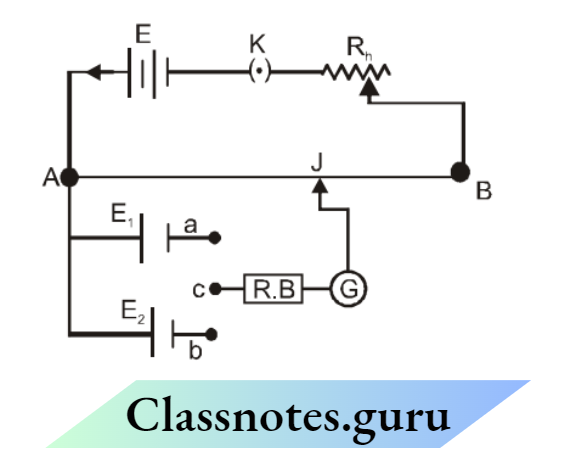
Theory:
- A potentiometer is an instrument designed for an accurate comparison of potential differences and for measuring small potential differences. In an ordinary form it consists of a long, uniform resistance wire of manganin or constantan stretched over a wooden board usually in 4 turns (or 10 turns) each of 100 cm in length.
- The wire is fixed at its ends to two binding screws. A metre-scale is fitted parallel to the wire and a sliding key or jockey is provided for contact.
- The working of a potentiometer can be understood by considering a simple diagram Let a wire AB be connected to a source of constant potential difference ‘E’ known as ‘ Auxiliary battery’.
- This source will maintain a current in the wire flowing from A to B and there will be a constant fall of potential from the end of A to B. This source thus establishes in the wire a potential difference per unit length known as the ‘potential Gradient’.
- If L is the length of the wire, this potential gradient will be E/L volts. Let one of the cells, whose E.M.F. ‘E 1’ is to be compared with the E.M.F. ‘E2’ of the other cell, be connected with its + ve electrode at A and the other electrode through a galvanometer to a movable contact i.e., jockey J.
- If the fall in potential between A and J due to the current flowing in the wire is equal to the E.M.F. ‘E 1’ of the cell, the galvanometer will show no deflection when the jockey is pressed at J indicating no current in the galvanometer. This position on the wire AB is possible only when E is greater Than E 1.

If the point J is at a distance l1 cm from A, the fall in potential between A and J will be E1= pl1 and therefore E1 1= pl at the null deflection.
If this cell is now replaced by the second cell of E.M.F. ‘E 2’ and another balance is obtained at a distance l 2 cm from A, then E2= p/l
therefore \(\frac{\mathrm{E}_1}{\mathrm{E}_2}=\frac{\rho l_1}{\rho l_2}=\frac{l_1}{l_2} \quad \text { or } \quad \frac{\mathrm{E}_1}{\mathrm{E}_2}=\frac{l_1}{l_2}\)
Since the galvanometer shows no deflection at the null point no current is drawn from the experimental cell and it is thus the actual E.M.F of the cell that is compared in this experiment.
Procedure:-
- Draw a diagram showing the scheme of connections
- Remove the insulation from the end of the connecting copper wires and clean the ends with sandpaper
- Connect the positive pole of the auxiliary battery (a battery of constant e.m.f) to the zero end (A) of the potentiometer and the negative pole through a one-way-key, an ammeter, and a low resistance rheostat to the other end of the potentiometer.
- Connect the positive pole of the cells E1 and E2 to the terminal at the zero and (A) and the negative poles to terminals a and b of the two-way key connect the common terminal c of the two-way key through a galvanometer (G) and a resistance box (R.B) to the jockey.
- To test the connections: – Introduce the plug-in position in the one-way-key (K) in the auxiliary circuit and also in between the terminals a and c of the two-way-key. Take out a 2,000 ohms plug from the resistance box (R.B). Press the jockey at the zero end and note the direction of deflection in the galvanometer.
- Press the jockey at the other end of the potentiometer wire; if the direction of deflection is opposite to that in the first case, the connections are correct. If the direction of deflection is in the same direction then increase the current in the auxiliary circuit with a rheostat till the deflection obtained in the galvanometer is in the opposite direction when the jockey is pressed at the other end.
- Move the jockey along the wire from the zero end A towards the other end B to find point J 1 where the galvanometer shows no defection. Put in the 2000 ohms plug in the resistance box and find the null point accurately. Note the length ‘l1’ of the wire and also the current in the ammeter.
- Disconnect the cell E: 1 and put the cell E2 in the circuit. Again remove the 2000 ohms plug from the resistance box and find the corresponding length (l2) accurately for no deflection of the galvanometer keeping the ammeter reading the same.
- Repeat the observation alternately for each cell again for the same value of current.
- Increase the current by adjusting the rheostat and obtain similarly, four sets of observations.
- (The rheostat used in the circuit should have a low resistance as compared to the resistance of the potentiometer wire.)
Observation and Calculations:

NEET Physics Class 12 Chapter 2 Measurement Errors and Experiments Notes
Mean \(\frac{E_1}{E_2}=\)
E.M.F of leclanche cell (E1) = ………….. volts
(By voltmeter)
E.M.F. of Daniel cell (E2) = ………. volts
(By voltmeter)
\(\frac{E_1}{E_2}=\)
Precaution: –
- The e.m.f. of the auxiliary battery should be constant and always greater than the e.m.f of either of the two cells, whose e.m.f are to be compared.
- The positive pole of the auxiliary battery and the positive poles of the cell must be connected to the terminal on the zero side of the potentiometer wire otherwise it would be impossible to obtain a balance point.
- The rheostat should be of low resistance and whenever the deflection shown is to the same side when a jockey is pressed at all points of the wire, the current must be increased to obtain the balance point at a desired length.
- The current should remain constant for each set of observations with the two cells.
- The current should be passed only for the duration it is necessary, otherwise the balance point will keep on changing.
- The balance points should be obtained at large distances from the zero end.
- The length should always be measured from the end of the wire where positive poles are connected.
- The balance point should be found alternately with the two cells.
- A high resistance should be used in series with the galvanometer. This does not affect the position of the balance point in any way. Near the position of the exact balance point, however, this resistance should be removed. (Note that the same purpose can be served by putting a shunt across the galvanometer)
- A resistance box should never be used in the auxiliary circuit.
- To avoid any change in the e.m.f. of a cell due to polarization, the reading should be taken after sufficient intervals of time.
Sources of Error :
- The potentiometer wire may not be uniform.
- The resistance of the wire may change due to the temperature rise.
- Contact potentials may not be negligible.
Experiment 18
Aim: To determine the internal resistance of a primary cell using a potentiometer.
Apparatus: A potentiometer, a Leclanche cell, a battery of three cells, an ammeter, a low resistance rhostat, two one-way keys a sensitive galvanometer two resistance boxes, a jockey connecting wires, and a piece of sane paper.

Theory
In the potentiometer circuit of Fig. let ‘l1’ be the length of the potentiometer wire upto the point X, when the balance is obtained with the cell (E) in an open circuit i.e. when key K2 is not closed, and ‘l2’ the length upto Y when the balance is obtained with the cell shunted through a resistance S. Then if E is the e.m.f. of the cell and ‘V’ the P.D. between its terminals when shunted, we have according to the principle of the potentiometer, and E1 and V2
⇒ \(\frac{\mathrm{E}}{\mathrm{V}}=\frac{l_1}{l_2}\)
If ‘r’ is the internal resistance of the cell and I the current through it when shunted by S, then by Ohm’s Law
⇒ \(\begin{array}{lll}
E=I(S+r) & \text { and } & V=I S \\
\frac{E}{V}=\frac{S+r}{S} & \ldots . \text { (2) }
\end{array}\)
From 1 and 2
⇒ \(1+\frac{\mathrm{r}}{\mathrm{S}}=\frac{l_1}{l_2}\)
Hence \(\mathrm{r}=\frac{\left(l_1-l_1\right) \mathrm{S}}{l_2}\)
Procedure
- Draw a diagram as shown in the scheme of connections in Fig.
- Remove the insulation from the ends of the copper wires and clean the ends with sandpaper. Connect the positive pole of the auxiliary battery to the zero end (A) of the potentiometer and the negative pole through a one-way key (K1), an ammeter, and a low resistance rheostat to the other end (B) of the potentiometer wire.
- Connect the positive pole of the cell (E) to the terminal at the zero end (A) and the negative pole the jockey through the galvanometer (G) and resistance box (R.B.)
- Connect a resistance box S across the cell (E) through a one-way key (K2)
- Insert the plug-in key K1 and adjust a constant current in the potentiometer circuit with the help of rheostat.
- Move the jockey along the wire to find a point where the galvanometer shows no deflection. Insert the 2000 ohms lug and find the null point accurately as at X. Note the length l1 of the wire and the current in the ammeter. Put in the key K2 take out 2 ohm plug from the resistance box S and make all other plugs tight by giving them a slight twist. Find the balance point again as at Y and note the corresponding length l2 Repeat twice for the same value of the current in the auxiliary circuit and same shunt resistance in a similar manner.
- Remove the plugs from the keys K1 and K2. Wait for some time, insert the plug in the key K1, and find l 1 similarly keeping the current same. Put in the key K2, take out a resistance of 3 or 4 ohms, and find the length l1repeat similarly for S equal to 5
- Change the value of current in the external circuit by a slight amount and repeat observations as in Step 6.

Result
The internal resistance of Leclanche cell (r) = ….. ohms
Precautions
- The e.m.f. of the auxiliary battery should be constant and always greater than the e.m.f. of either of the two cells, whose e.m.fs. are to be compared.
- The positive pole of the auxiliary battery and the positive poles of the cells must be connected to the terminal on the zero side of the potentiometer wire otherwise it would be impossible to obtain the balance point
- The rheostat should be of a low resistance and whenever the deflection shown is to the same side when a jockey is pressed at all points of the wire, the current must be increased to obtain the balance point at a desired length.
- The current should remain constant for each set of observations with two cells.
- The current should be passed only for the duration it is necessary, otherwise, the balance point will keep on changing
- The balance points should be obtained at large distances from the zero end.
- The internal resistance of a Leclanche cell is not constant but varies with the current drawn from the cell. Hence to get constant readings the resistance from the resistance box S must be varied by a small amount (say 3 to 8 ohms).
- [Note, To prevent a large current from being passed through the galvanometer either shunt it with a wire or put a large resistance of about 2000 ohms in series with it. But when the balance point is located, to find it more precisely the shunt should be removed or all the plugs of the series resistance box should be inserted].
Exercise
Question 1. A student is required to measure the emf of a cell, he should use –
- Potentiometer
- Voltmeter
- Ammeter
- Either 1 or 2
Answer: 1. Potentiometer
Question 2. A potentiometer is an ideal device for measuring potential differences, because-
- It uses a sensitive galvanometer
- It does not disturb the potential difference it measures
- It is an elaborate arrangement
- It has a long wire hence heat developed is quickly radiated
Answer: 2. It does not disturb the potential difference it measures
Question 3. Which of the following statements is correct during the measurement of emf of the cell by a potentiometer?
- No current flows through the potentiometer wire upto position of a null point
- At the null point in any potentiometer experiment, no current flows through the whole of the potentiometer wire.
- No current is drawn from the cell when the null point is obtained
- No current is drawn from the battery when the null point is obtained
Answer: 3. No current is drawn from the cell when the null point is obtained
Question 4. Which of the following statements is not wrong?
- To increase the sensitivity of a potentiometer increase current through potentiometer wire.
- To increase sensitivity increase external resistance in the battery circuit connected to the potentiometer.
- To increase sensitivity increase battery voltage
- To increase sensitivity increase the emf of battery.
Answer: 4. To increase sensitivity increase the emf of battery.
Experiment 9
Aim:
To find the resistance of a galvanometer by half deflection method and find its figure of merit.
Apparatus:
A Weston type moving coil galvanometer, a cell, two resistance boxes, two one-way keys, a voltmeter, connecting wires, and sandpaper.

Theory –
The connections for finding the resistance of a galvanometer by the half deflection method are shown in Fig. When the key, K1 is closed, keeping the key K2 open, the current Ig through the galvanometer is given by
⇒ \(I_g=\frac{E}{R+G}\) where E = E.M.F. of the cell.
R = Resistance from the resistance box R.B.
G = Galvanometer resistance.
If j is the deflection produced, then \(\frac{E}{R+G}=k \theta\)
If now the key K2 is closed and the value of the shunt resistance S is adjusted so that the deflection is reduced to half of the first value, then the current flowing through the galvanometer I’g is given by \(I_g^{\prime}=\frac{E}{R+\frac{G S}{(G+S)}}\left(\frac{S}{G+S}\right)=\frac{k \theta}{2}\) or, \(I_g^{\prime}=\frac{E S}{R(G+S)+G S}=\frac{k \theta}{2}\) Comparing (1) and (2), we get R + G) 2S = R(G + S) + GS or (R – S) G = RS or \(G=\frac{R S}{R-S}\) If the value of R is very large as compared to S, then \(\frac{R S}{R-S}\) is nearly equal to unity. Hence g=S
The figure of Merit:-
The figure of merit of a galvanometer is that much current is sent through the galvanometer to produce a deflection of one division on the scale. If k is the figure of merit of the galvanometer, and ‘k’ is the number of divisions on the scale, then (Ig) through the galvanometer is given by ig=Kθ
Procedure:-
- Draw a diagram showing the scheme of connections as in fig. and make the connections accordingly.
- Check the connections and show the same to the teacher before passing the current.
- Introduce a high resistance R from the resistance box (R. B), close the key K1, and adjust the value of R till the deflection is within scale and maximum. Note the deflection and the value of the resistance R.
- Close the key K2 and adjust the value of the shunt resistance S so that the deflection is reduced exactly to half the first value. Note this deflection and the value of the resistance S.
- Repeat the experiment three times taking different deflections of the galvanometer.
To find the figure of merit: –
Find the e.m.f. of the cell by a voltmeter. See the positive of the cell connected to the positive marked terminal of the voltmeter.
Connect the cell E, the galvanometer G, the resistance box R.B., and the key K1 in series take out a 5,000 ohms plug from the resistance box, and make all other plugs tight. put in the key K1 and adjust the value of the resistance R from the resistance box so that a deflection θ near about 30 divisions is indicated in the galvanometer. Note the deflection θ in the galvanometer and also the value of the resistance R from the resistance box.

Adjust the value of R from the resistance box to get a deflection of about 20 divisions and again note the deflection and the resistance.
Increase the number of cells to two. Find the e.m.f and the value of the resistance R to get a deflection of about 30 and again about 20 divisions as in the previous step.
Resistance of Galvanometer:

Mean Value of G = …………. ohms
Figure of merit: –
- Galvanometer resistance (G) = ……….Ω
- Number of division on the galvanometer scale = …………..

Precautions: –
- The value of ‘R’ should be large
- To decrease the deflection, the shunt resistance should be decreased and vice-versa.
- In this method, it is assumed that the deflection is proportional to the current. This is possible only in a weston type moving coil galvanometer.
- The connections must be tight and the ends of connecting wires should be cleaned.
Experiment 20
Aim: To find the focal length of a convex mirror using a convex lens.
Apparatus: An optical bench with four uprights, a convex mirror, a convex lens, a knitting needle, and a half-meter scale.

Suppose a convex lens L is interposed between a convex mirror M and an object needle O as. When the relative position of M, L, and O are adjusted in such a way that there is no parallax between the object needle O and its image I, then in that position, the rays will fall normally on the convex mirror M.
The rays which fall on the mirror normally should meet at the centre of curvature C of the mirror when produced. The distance MC gives the radius of curvature R. Half of the radius of curvature gives the focal length F of the mirror.
Now without disturbing the positions of the object O and the lens L, the convex mirror is removed and another needle is placed in the position of the image I of the object O, formed by the lens L by using the parallax method.
Measure MI’ Now \(f,=\frac{R}{2}=\frac{M I}{2}\)
Procedure
- Mount the convex mirror M, a convex lens L, and the object needle O on an optical bench. Look for the inverted image of O through the system of the lens L and the mirror M by adjusting the position of O or L for that of the mirror. When the inverted image is not obtained, a convex lens of a larger focal length should be used.
- Remove the parallax between the object needle O and its inverted image and note the position of O, L, and M on the bench scale.
- Remove the mirror M and do not disturb the lens L and O at all. Take another needle I’ and place it on the other side of the lens.
- Take five sets of observations for different positions of O and L.
- Determine the index correction between the mirror M and the image needle I’.
Observation and Calculations:
- Index correction
- Length of the knitting needle, y = ……… cm
- Observed distance with the needle between M and I’ x = ……… cm
- Index correction between M and I = (y – x) = ……… cm

- Mean, MI’ = …….. cm
- Corrected distance, MI’ = …….. cm
- therefore \(\mathrm{f}=\frac{\text { CorrectedMI’ }}{2}=\ldots \ldots . . . \mathrm{cm}\)
Result:
The focal length of the given convex mirror =…….. cm
Precautions:
- The line joining the pole of the mirror, the centre of the lens L, and the tip of the needle, should be parallel to the length of the optical bench.
- The auxiliary lens L must have a sufficiently large focal length.
- The parallax should be removed tip to tip while removing the parallax, the eye should be kept at the least distance of distinct vision i.e., 25 cm away from the needle.
- In the second part of the experiment i.e., after removing the mirror M, the position of L and O should not be disturbed at all.
Experiment 20 (2)
Aim: To find the focal length of a convex lens by plotting graphs between u and v and between 1/u and 1/v.
Apparatus: A convex lens of short focal length (say 15 to 20 cm.), two needles, three uprights, one clamp, an optical bench a half-meter rod, and a knitting needle.
Theory: The position of the image formed by a convex lens depends upon the position of the object the lens below shows the different positions of the images formed by a convex lens for different object positions. The relation between u, v, and f for a convex lens is \(\frac{1}{f}=\frac{1}{v}-\frac{1}{u}\)
Procedure
Find the rough focal length of the given convex lens by focusing a sharp, clear, and inverted image of a distant object on a white paper and measuring this distance between the lens and the white paper with a meter scale.
If the optical bench is provided with leveling screw, then level it using a spirit level.
Mount the convex lens (held in its holder) on the central upright of the optical bench. Also, add the two needles on the remaining two uprights. Arrange the tips of the needles at the same vertical height as the centre of the lens.


Mark one needle as AB object needle and the other one CD as an image needle and distinguish between them by rubbing the tip of one of the needles with a piece of chalk or putting a paper flag on it.
Find the index corrections for u and v using a knitting needle.
Shift the position of the object needle AB to a distance greater than 2f from the lens. Look from the other side of the lens along its principal axis near the end of the bench. If the setting is correct, an inverted, real image A’B’ is seen. Now adjust the position of the second needle CD such that the parallax between the image of the object needle and the image needle is removed. The position of the second needle is so adjusted that the parallax is removed from tip to tip.
Note the positions of the lenses, the object needle, and the image needle on the bench scale and thus find the observed values of u and v. Apply index corrections to get the corrected values for u and v.
Repeat the above steps for 5 different positions of the object by placing it beyond 2F and between F and 2F. Record your observations as detailed below.
Observations:
- Approximate focal length of length of the lens f = …….. cm
- For index correction
- The actual length of the knitting needle x = …….. cm
For u
- Observed distance between the object needle and the lens
- When a knitting needle is inserted between them, y = …….. cm
- Index error for u, e
- 1 = (y – x) = …….. cm
3. Index correction for u, –e 1 = (x – y) = …….. cm
For v
- Observed distance between the image needle and the lens
- When the knitting needle is inserted between them, z = …….. cm
- Index error for v, e
- 1 = (z – x) = …….. cm
- Index correction for v –e 2 = (x – z) = …….. cm

Plotting Graphs and Calculations of f
u – v Graph
Choose a suitable but the same scale to represent u along the x-axis and v along the y-axis Remember that u is negative and v is positive for a convex lens, according to the coordinate sign convention used these days.
Plot the points for various sets of values of u and v from the observation table. The graph will be a rectangular hyperbola.

Find f from this graph: Draw a line OC bisecting the angle X’ OY and cutting the graph at point C. The coordinates of this point are (–2f, 2f). Note the distances of the foot of the perpendiculars OA and OB respectively on the X and Y axis. Half of these distances are given the focal length of the convex lens. Thus \(\mathrm{f}=\frac{\mathrm{OA}}{2}=\ldots \ldots . . \mathrm{cm}\)
Take the mean of these two values of f.
Calculation of f from graph between 1/u and 1/v: Choose a suitable but the same scale to
represent \(\frac{1}{u}\) along x-axis and ,\(\frac{1}{v}\)
along y-axis, taking O as the origin (0,0).
Plot the graph between \(\frac{1}{u}\) and \(\frac{1}{v}\) The graph would be a straight line as shown in the figure below making equal intercepts (OA and OB) on them measure AO and OB. Then \(f=\frac{1}{O A}=\frac{1}{O B}\)……………………..cm

Result:
The focal length of the given convex lens as determined from the graph of (u, v) from fig. above =………… cm.
\(\left(\frac{1}{u}, \frac{1}{v}\right)\) above= cm
Precaution
- The tips of the needles should be as high as the optical centre of the lens.
- The uprights carrying the lens and the needles should not be shaky.
- Parallax should be removed tip to tip.
- The eye should be placed at such a position that the distance between the image needle and the eye is more than 25 cm.
- The image and object needles should not be interchanged for different sets of observations.
- A piece of chalk may be rubbed on the tip of the object needle or a paper flag put on it, to distinguish it from the image needle.
Exercise
Question 1. By plotting \(\frac{1}{v}\) versus \(\frac{1}{u}\) focal length of a convex mirror can be found-
- No, as it forms a virtual image
- Yes, only if the scale is large
- Yes, only if the scale is small
- Yes, only if the aperture is small
Answer: 1. No, as it forms a virtual image
Question 2. The focal length of which of the following can not be obtained directly-
- Convex Mirror And Convex Lens
- Convex Mirror & Concave Lens
- Convex Lens And Concave Mirror
- Concave Lens And Concave Mirror
Answer: 2. Convex Mirror & Concave Lens
Question 3. Which of the following statements is false –
- The bench correction is always equal to the negative of the bench error
- The larger the distance between the two objects larger the magnitude of parallax
- Parallax disappears if the positions of two objects coincide
- Parallax can occur between any two objects
Answer: 2. The Larger the distance between the two objects larger the magnitude of parallax
Question 4. The focal length of a convex mirror is obtained by using a convex lens. The following observations are recorded during the experiment
- Object Position = 5 Cm
- Lens = 35.4 Cm
- Image = 93.8 Cm
- Mirror = 63.3 Cm
- Bench Error = –0.1 Cm
Then The Focal Length Of the Mirror Will Be
- 7.5 cm
- 8.4 cm
- 15.3 cm
- None Of These
Answer: 3. 15.3 cm
Question 5. For spherical mirrors, graph plotted between \(-\frac{1}{V} \text { and }-\frac{1}{u} \text { is – }\)
- A straight line with slope 1
- Straight line with slope – 1
- Parabola
- None
Answer: 2. Straight line with slope – 1
Experiment 21
Aim: To determine the angle of minimum deviation for a given glass prism by plotting a graph between the angle of incidence and angle of deviation and hence find the refractive index of the material of the prism.
Apparatus
A drawing board, a sheet of paper, a glass triangular prism, pins, a half-meter scale, a graph paper, and a protractor.
Theory:
Refraction Through a prism (angle of minimum deviation)
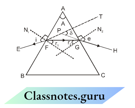
Minimum Deviation – In (Fig 1), ABC represents the principal section of a glass prism. Let EF be a ray of light that is incident on the refracting face AB of the prism. The straight path FG represents the refracted ray through the prism and GH represents the emergent ray. FN 1 and GN 2 are drawn normal to the refracting faces AB and AC at points F and G respectively.
Incident ray EF is Produced to PT, and as a result of refraction through the prism, ABC emerges along GH. The incident ray shown as EF (extruded as dotted line FPT) deviates and follows the path PGH. The angle is the angle between the incident ray EFPT (produced) shown dotted and the emergent ray GH (produced backward) to meet EFT at point P.
This angle is known as the angle of deviation. the angle BAC of the prism (i.e., the angle between its two refracting faces) is called the angle of the prism and it is denoted by the letter ‘A’ It can be proved from simple geometrical considerations that \(\angle \mathrm{A}+\angle \delta=\angle \mathrm{i}+\angle \mathrm{e}\)
and A = r1 + r2 …….2
where i = angle of incidence
- e = angle of emergence
- r1 = angle of refraction at face AB
- r2 = angle of refraction at face AC.
The relation (1) clearly shows that the angle of deviation s varies with the angle of incidence i.
The variation of angle s with angle i is represented graphically
The angle i0 decreases with the increase in the value of i initially, till a particular value (i) of the angle of incidence is reached. For this value of angle of incidence, the corresponding value of the angle of deviation is minimum and it is denoted by the letter m.
This angle of deviation is called the angle of minimum deviation. When a prism is so placed concerning the incident ray that the angle of deviation produced by it is minimum, then the prism is said to be in the position of minimum deviation. In this position, the following relation holds between the angles.
⇒ \(\text { i.e., } \angle \mathrm{i}=\angle \mathrm{e} \text { and } \angle \mathrm{r}_1=\angle \mathrm{r}_2\)
In this position, the incident ray and the emergent ray are symmetrical concerning the prism and the ray passes through the prism is parallel to its base. The refractive index of the material of the prism is given as
\(\mu=\frac{\sin \left(\frac{A+\delta_m}{2}\right)}{\sin \frac{A}{2}}\)
Where sm is the angle of minimum deviation and A is the angle of the prism. Variation of the angle of deviation with the angle of incidence for refraction through a prism

Procedure:
Fix the sheet of white paper on the drawing board with cello tape or drawing pins.
Draw a straight line XY nearly at the centre of the sheet parallel to its length. Mark points marked as O at suitable spacing on this line XY and draw normal to the line XY at points O as Draw straight line PQ corresponding to the incident rays that are drawn at angle of incidence ranging from 30º to 60º, i.e., for angles of 30º, 40º, 50º and 60º using a protractor.
Place the prism with one of its refracting surfaces on the line XY and trace its boundary
ABC.

Fix two pins P and Q about 8 cm apart on the incident ray line and view its image with your one eye closed from the face BC of the prism. Fix two pins R and S on the paper such that the tips of these pins and the tips of the images of the incident ray pins P and Q all lie on the same straight line.
Remove the pins R and S and encircle their pinpricks on the paper. Remove the pins P
and Q and also encircle their pinpricks.
Join the points (i.e., pinpricks) S and R and produce it backward to meet the incident
ray PQ produced (shown by dotted lines). Thus RS is the emergent ray corresponding to
the incident ray PQ. Draw arrowheads to show the direction of the rays.
Measure the angle of deviation with a protractor.
Repeat the steps (3 to 7) for different values of angle of incidence and measure the corresponding angles of deviation. Take at least seven values of angle i ranging from 30º – 60º.
Measurement of refracting angle ‘A’ of the prism.
Draw a line XY on the drawing sheet as depicted

Mark points O in the middle of XY and E and F on either side of O equidistant from E such that OE = OF (say 1 cm each).
Draw three vertical lines EG, OI, and FH through E, O, and F respectively, such that these are parallel to each other.
Place the prism with its refracting edge A on the line Ol such that BC is along XY. The
points E and F would be symmetric for edges B and C.
Draw the boundary ABC of the face of the prism touching the board.
Fix pins P1 and P2 vertically, 4 cm apart, observe their reflection in the face AB, and fix pin P3 such that the images of P1, P2, and P3 are in a straight line. Fix another pin P4 such that prick of P4 is also in the same straight line. Join the pricks of P3 and P4 by line LK and produce it backward. KL is a reflected ray of incident ray GK.
Similarly, locate NM by joining P’ 3 P’4 as the reflected ray of incident ray HM. Draw NM
backward to meet the line LK product backward at point P. The point P should lie on the
line OI if observations are correctly taken.
The angle LPN is equal to 2<A(it can be proved geometrically from the figure). Measure
the angle LPN and determine <A, the angle of the prism.
Observations:
Table for angles i and δ

Plotting the graph between <i and <δ Plot a graph between angles I and δ for various sets of values recorded in the observation table. The graph will be a curve
For angle ‘A’ of prism
LPN = ………..°= 2A or Angle A =…………°
Calculations: Determine the angle of minimum deviation m from the graph.
Result: The angle of deviation δ first decreases with the increase in the angle of incidence, attains a minimum value and then increases with further increase in the angle of incidence as indicated in the (δ—i) graph
Percautions:
- A sharp pencil should be used for drawing the boundary of the prism.
- The separation between the pins should not be less than 8 cm.
- The angle of incidence should lie between 30° to 60°.
- The same angle of prism should be used for all the observations. So an ink mark should be placed on it to distinguish it as the refracting angle A of the prism.
- The pins should have sharp tips and be fixed vertically and the pinpricks should be encircled immediately after they are removed.
- Proper arrows should be drawn to indicate the incident, the refracted, and the emergent rays.
- A smooth curve practically passing through all the plotted points should be drawn.
NEET Physics Class 12 Chapter 2 Measurement Errors and Experiments Notes
Experiment 22
AIM: To determine the refractive index of a glass slab using a traveling microscope.
Apparatus:
A piece of paper, a marker, a glass slab, a traveling microscope, and lycopodium powder.
Theory:
Refraction is a phenomenon of propagation of light from one transparent medium into the other medium such that light deviates from its original path. The ratio of the velocity of light in the first medium to that in the second medium is called the refractive index of the second medium concerning the first.
Usually, the first medium is air. The bottom surface of a vessel containing a refracting liquid appears to be raised, such that the apparent depth is less than the real depth. The refractive index of the refracting liquid is defined as the ratio of real depth to the apparent depth.
Mathematically, Refractive index \(\mu=\frac{\text { real depth }}{\text { apparent depth }}\)
For accurate measurements of depths, a traveling microscope is used. If the reading of real depth at the bottom of the slab is r1, if the reading at the cross due to refraction is r2, and at the top of the slab if the reading is r3, then real depth = r3 — r1, and apparent depth = r3 — r2.
Therefore , refractive index of glass (material of slab)\(\mu=\frac{r_3-r_1}{r_3-r_2}\)

Procedure:
- For accurate measurement of depth, a traveling microscope is used.
- Note the number of divisions of vernier which coincide with several full-scale divisions.
- Find the value of each main division and hence the least count of the microscope scale as (1 M.S.D —V.S.D)
- Set the microscope in its stand such that it is capable of sliding vertically up and down
as the screw attached to the rack and pinion is turned. - On a sheet of white paper, a cross and place it below the objective of the microscope.
- Move the microscope very gently. Using the screw, focus the eyepiece on the cross mark and
bring the cross in focus such that the cross wires, coincides with the marked cross on
the paper. Note the reading of the microscope as r1. - Place the given glass slab on the cross mark. You would observe that the cross-mark
appears to be raised. - Move the microscope gradually and gently upward to bring the cross mark in focus and
on the cross of cross wires. Record the reading as r2 - Sprinkle some fine lycopodium powder on the glass slab and move the microscope upward
till the powder particles come into focus. Record the reading on the scale as r3. - The difference of readings r3 and r1 i.e. r3 — r1 gives the real depth whereas r3—r2 gives the
apparent depth. - Record your observations as follows and calculate the value of refractive index m.
Observations:
- Least count of traveling microscope.
- 10 Vernier Scale Division = 9 Main Scale Divisions (Scales may differ from instrument to instrument).
- Value of one main scale division = 1mm i.e. 0.1 cm.
- 10 V.S.D =9 M.S.D (V.S.D. Vernier Scale Division, M.SD. Main Scale Divisions)
⇒ \(\text { 1V.S.D }=\frac{9}{10} \text { M.S.D }\)
⇒ \(\text { L.C }=1 \text { M.S.D }-1 \text { V.S.D }=1 \text { M.S.D }-\frac{9}{10} \text { M.S.D }=\frac{1}{10} \text { M.S.D or } \frac{1}{10} \times 0.1 \mathrm{~cm}=0.01 \mathrm{~cm}\)

Mean values r1 =…….cm, r2=……..r3=……cm
Calculations:
Real depth = d r= r3 – r1 =……. cm.
Apparent depth = da = r3 – r2 =……. cm.
Refractive index \(\mu=\frac{\text { Real depth }}{\text { Apparent depth }}=\frac{\mathrm{d}_{\mathrm{r}}}{\mathrm{d}_{\mathrm{a}}}=\ldots \ldots .\)
Percautions:
- The least count of the scale of the traveling microscope should be carefully calculated.
- Microscope once focussed on the cross mark, the focussing should not be disturbed
throughout the experiment. - Eyepieces should be adjusted such that cross wires are distinctly seen.
- Cross wires, the cross should be set on the ink cross mark on the paper.
- Only a thin layer of powder should be spread on the top of the slab
- Express your result upto significant figures keeping in view the least count of instruments.
Result
The refractive index of the glass slab by using a traveling microscope is determined as
Experiment 23
Aim: To study the static and dynamic curves of a p–n junction diode in forward bias and to determine its static and dynamic resistances
Apparatus: A p-n junction diode, a3V battery, a high resistance rheostat, 0-3 volt voltmeter, one milliammeter, one-way key, and connecting wires.
Theory: When a junction diode is forward biased, a forward current is produced which increases with an increase in bias voltage. This increase is not proportional.
The ratio of forward bias voltage (V) and forward current (I) is called the static resistance of semiconductor diode, i.e., \(R=\frac{V_F}{I_F}\)
In case of a varying bias voltage and varying forward current, the ratio of change in forward bias voltage(V) and the corresponding change in forward current (I)is called the dynamic resistance \(\left(r=\frac{\Delta V_F}{\Delta \mathrm{I}_{\mathrm{F}}}\right)\)
To find the static and dynamic resistance of the semiconductor diode, a graph has to be plotted between forward bias voltage(V) and forward bias current (I). This graph is called the characteristic curve of a semiconductor diode.
Producer:

- Make the connections as shown in the figure.
- Keep the moving contact of the rheostat to the minimum and insert the key K. Voltmeter and milliammeter will show a zero reading.
- Move the contact towards the positive to apply the forward bias voltage V = 0.1 V.
- The current remains zero
- Increase the forward bias voltage to 0.3 V in steps. The current will still be zero. (This
is due to the junction potential barrier of 0.3 V). - Increase V to 0.4 V. Record the current.
- Increase V in the step of 0.2 and note the corresponding current.
- At V = 2.4 V. The current increases suddenly. This represents the forward breakdown
stage. - Draw a graph of I on y- the y-axis and V on the x-axis.
Record of Readings
- Least count of voltmeter = ………V Zero error of mA = ………mV
- Least count of milliammeter = ………mA Zero error of voltmeter = ………V

Calculations
For static resistance (R)
⇒ \(R=\frac{V_F}{I_F}\)
From the graph \(\mathrm{R}=\frac{\mathrm{OA}^{\prime}}{\mathrm{OA}^{\prime \prime}}=\ldots \ldots . . . ., \text { ohm }\)
Diode is …… (specify the code)
For dynamic resistance (r)
⇒ \(r=\frac{\Delta V_F}{\Delta \mathrm{I}_{\mathrm{F}}}\)
From the graph \(r=\frac{A C}{B C} \text { ohms }\)
Result
- The static resistance of the given semiconductor diode = ……….. ohm
- The dynamic resistance of the given semiconductor diode = ……….. ohm
Precautions
- Make all connections neat, clean, and tight
- The key should be used in the circuit and opened when the circuit is not in use
- Avoid applying forward bias voltage beyond the breakdown
- Possible sources of errors
- The connection may not be tight
- The junction diode may be faulty
Experiment 24
AIM: To draw the characteristic curves of a Zener diode and to determine its reverse breakdown voltage.
Apparatus: A zener diode (with a reverse breakdown voltage of 6 V), a ten-volt battery, a rheostat, two voltmeters (range 0, 10 V), one milliammeter, one 20 resistance, one-way key, connecting wires.
Theory:
A Zener diode is a semiconductor diode in which the n-type sections are heavily doped, This heavy doping results in a low value of reverse breakdown voltage. The reverse breakdown voltage of the Zener diode is called Zener voltage (Vz). The reverse current that results after the breakdown is called zener current (Iz).
Vi = Input voltage
V0 = Output voltage
Ri = Input resistance
Ii = Input current
Iz= Zener diode current
IL = Load current
IL = Ii – Iz
V0 = Vi – Ri Ii
V0 = RL IL
Initially, as Vi increases, Ii increases hence V0 increases linearly. At break-down, the increase of Vi increases I i by a large amount, so that V0 = Vi – RiI i becomes constant. This constant value of V 0 Which is the reverse breakdown voltage, is called zener voltage.

Procedure:
- Make the connections as shown in the figure above making sense that the Zener diode is reverse biased Bring the moving contact to a rheostat to the minimum and insert the key K. Voltmeter and ammeter will read zero
- Move the contact a little towards the positive end to apply some reverse bias voltage (Vi). Milliammeter reading remains zero.
- As Vi is further increased, Ii starts increasing and V0 becomes less than Vi. Note the values of Vi V0 and Ii.
- Keep increasing Vi in small steps of 0.5 V. Note the corresponding values of I i and V0
- At one stage as Vi is increased, Ii increases by a large amount and V0 does not increase. this is a reverse breakdown situation.
- As Vi is increased further, I will increase keeping V0 constant. Record your observation in a tabular column
- Draw a graph of output voltage V0 along the y-axis and input voltage along the x-axis. The graph will be as shown in the figure.
- Draw a graph of input current along the y-axis and input voltage along the x-axis. The graph will be shown in the figure

Result:
The Breakdown voltage of the given Zener diode is 6 volts.
Percautions:
- Use voltmeter and milliammeter of suitable range.
- Connect the zener diode p-n junction in reverse bias.
- The key should be kept open when the circuit is not in use.
Experiment 25
AIM: To study the characteristics of a common emitter n-p-n or p-n-p transistor and to find out the values of current and voltage gains.
Requirements: An n-p-n transistor, a 3 V battery, a 30 V battery, two rheostats, one 0–3 V voltmeter, one 0–30 V voltmeter, one 0–500 A microammeter, one 0–50 mA milliammeter, two-way keys, connecting wires.
Theory:
A transistor can be considered as a thin wafer of one type of semiconductor between two layers of another type. An NPN transistor has one p-type wafer in between two n-type. Similarly p-n-p the transistor has one n-type wafer between two p-type.
In a common emitter circuit, the emitter base makes the input section and the collector base the output section, with the emitter-base junction, forward bise, and the collector-base junction, reverse biased. The resistance offered by the emitter-base junction is called input resistance Ri and has a low value.
The resistance offered by the collector-base junction is called output resistance R0 and has a high value. Due to the high output resistance, a high resistance can be used as a load resistance.
The ratio \(\frac{R_L}{R_i} \text { or } \frac{R_0}{R_i}\) measures the resistance gain of the common emitter transistor. The ratio of change in collector current to the corresponding change in base current measures the current gain in the common emitter transistor and is represented by B.
⇒ \(\beta=\frac{\Delta \mathrm{I}_{\mathrm{c}}}{\Delta \mathrm{I}_{\mathrm{b}}}\)
The product of current gain and the resistance gain measures the voltage gain of the common emitter transistor.
Formula Used
Input resistance, \(\mathrm{R}_{\mathrm{i}}=\frac{\Delta \mathrm{I}_{\mathrm{b}}}{\Delta \mathrm{I}_{\mathrm{b}}}\)
Out put resistance, \(\mathrm{R}_0=\frac{\Delta \mathrm{V}_{\mathrm{c}}}{\Delta \mathrm{I}_{\mathrm{c}}}\)
Resistance again, \(=\frac{R_0}{R_i}\)
Current gain, \(\beta=\frac{\Delta \mathrm{I}_{\mathrm{c}}}{\Delta \mathrm{I}_{\mathrm{b}}}\)
Voltage gain correct gain x resistance gain
i.e., \(A_v=\beta \frac{R_0}{R_i}\)
Circuit Diagram

Procedure
- Make a circuit diagram as shown in Figure (A)
- Drag the moveable contact of rheostat to the minimum so that voltmeters, V1 and V2 read zero volt
For Input Characteristics
- Apply the forward bias voltage at the emitter-base junction note the base voltage (Vb) and the base current (I b)
- Keep increasing Vb till I b rises suddenly
- Make collector voltage 10 V and repeat the above steps
- Now make collector voltage 20 V, 30 V, and repeat the above steps. Note the value of Vb and I b in each case
For Output Characteristics
- Make all reading zero. Keep the collector voltage zero.
- Make base current I b = 100 uA by adjusting the base voltage. You will be able to read some collector current even though the collector voltage is zero.
- Make the collector voltage 10V, 20V, 30V, etc., and note corresponding collector currents. Record your observations in the tabular form as given below.
- Make the current I b equal to 200 uA, and note the values of I c corresponding to the different values of V.
Record Of Reobservations
- Least count of voltmeter, V1 = ………V
- Least count of voltmeter, V2 = ………V
- Least count of milliammeter = ………mA
- Least count of microammeter = ………uA


Graphs
I (For Input Characteristics)
Draw a graph of base voltage (Vb) on the x-axis and base current (I b) on the y-axis from table no. 1. The graph.
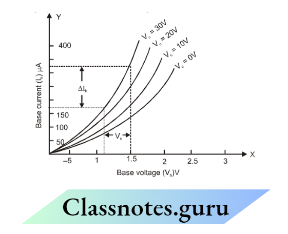
The slope of the graph gives the value of \(\frac{\Delta \mathrm{I}_{\mathrm{c}}}{\Delta \mathrm{V}_{\mathrm{c}}}\) and its reciprocal gives the value of input resistance R1
⇒ \(\mathrm{R}_1=\frac{\Delta \mathrm{V}_{\mathrm{b}}}{\Delta \mathrm{I}_{\mathrm{b}}}=\ldots \ldots . . \mathrm{ohms}\)
2 For Output Characteristics
Draw the graph between collector voltage Vc and colletor current I c for 10 mA base current I b taking Vc along the x-axis and Ic along the y-axis from table no.2. The graph will be as shown in the figure.

From the graph, the slope gives the value of \(\frac{\Delta \mathrm{I}_{\mathrm{c}}}{\Delta \mathrm{V}_{\mathrm{c}}}\) and its reciprocal gives the output resistance. \(\mathrm{R}_0=\frac{\Delta \mathrm{V}_{\mathrm{c}}}{\Delta \mathrm{I}_{\mathrm{c}}}=\ldots \ldots \ldots . \mathrm{ohm}\)
3 For Calculation of Current Gain
Plot a graph of base current (I b) on the x-axis and collector current Ic on the y-axis. The graph will be as shown in the figure.
The slope of the graph will give the value of \(\frac{\Delta \mathrm{I}_{\mathrm{c}}}{\Delta \mathrm{I}_{\mathrm{b}}}\) which is the value of current gain (b).

- AC = …………………..mA= …………………..A
- BC = …………………..uA= …………………..A
⇒ \(\beta=\frac{A C}{B C}=\)
For calculation of voltage gain (Av)
Voltage gain = Current gain × Resistance gain \(A=\beta \times \frac{R_0}{R_i}\)
Result:
For the given common emitter transistor, Current gain b= ………
Votage gain Av = ……….
Percautions:
- Use voltmeter and milliammeter of suitable range
- The key should be kept open when the circuit is not in use
Possible Sources Of Error:
- Voltmeter and ammeter may have a zero error
- All the connections may not be tight
Experiment 26
AIM: To identify a diode, an L.E.D., a transistor, a resistor, and a capacitor from a mixed collection of such item
Apparatus: A multimeter and a collection of a junction diode, L.E.D., a transistor, a resistor, a capacitor and an integrated circuit.
Theory:
- For identification of different items, we have to consider both, their physical appearance and working
- An IC (integrated circuit) is in the form of a chip (with a flat back) and has multiple terminals,
say 8 or more. Therefore, it can easily be identified. - A transistor is a three-terminal device and can be sorted out just by appearance
- A resistor, a capacitor, a diode, and an LED are two terminal devices. To identify these we
use the following facts: - A diode is a two-terminal device that conducts only when it is forward-biased
- An LED is a light-emitting diode. It is also a two-terminal device which conducts and emits light
only when it is forward-biased. - A Resistor is a two-terminal device. It conducts both with d.c. voltage and a.c. voltage. Further, a resistor conducts equally even when terminals of d.c. the battery is reversed.
- A capacitor is a two-terminal device that does not conduct with d.c. voltage applies either way. But, conducts with a.c. Voltage.

Producer:
- Look at the given mixture of various components of an electrical circuit and pick up the one having more than three terminals. The number of terminals maybe 8, 10, 14, or 16. This component will have a flat face. This component will be the integrated circuit i.e., IC.
- Now find out the component having three legs or terminals. It will be a transistor
- The component having two legs may either be a junction or capacitor or resistor or a light-emitting diode. These items can be distinguished from each other by using a multimeter as an ohmmeter.
- Touch the probes to the two ends of each item and observe the deflection on the resistance scale. After this, interchange the two probes and again observe the deflection.
- If the same constant deflection is observed in the two cases (before and after interchanging
the probes), the item under observation is a resistor. - If unequal deflections are observed, it is a junction diode.
- If unequal deflections are observed in the two cases along with the emission of light in the
- case when the deflection is large, the item under observation is an LED
- On touching the probes, if a large deflection is observed, which then gradually decreases to zero the item under observation is a capacitor.
- In case the capacity of the capacitor is of the order of picofarad, then the deflection will become zero within no time.
Result:
When the item is observed physically

NEET Physics Class 12 Chapter 2 Measurement Errors and Experiments Notes
With a multimeter as an ohmmeter:

Percautions:
Observe all those precautions that were related to a multimeter and explain at the end of a multimeter.
Experiment 27
AIM: Use of multimeter to:
- Identify the base of the transistor.
- Distinguish between N-P-N and P-N-P type transistors.
- Identify terminals of an IC
- See the unidirectional flow of current in the case of a diode and LED.
- Check whether the given electronic component (e.g., diode, transistor, or IC) is in working order.
Apparatus
A multimeter, P-N-P transistor, N-P-N transistor, an IC, junction diode, L.E.D., etc
Theory:
Multimeter: It is an electrical instrument that can be used to measure all three electrical quantities i.e., electrical resistance, current (a.c. and d.c.), and voltage (direct and alternating). Since it can measure Ampere (A) (unit of current), Volt (V) (Unit of e.m.f), and Ohm (unit of resistance), that is why also called an AVO meter. In this single instrument will replace the voltmeter and Ammeter.
Construction
The most commonly used form of the multimeter is shown in the figure, which is a pointer-type moving coil galvanometer. The pointer of the multimeter can move over its dial, which is marked in resistance, current, and voltage scales of different ranges.
The zeros of all the scales are on the extreme left, except that of the resistance scale, whose zero is on the extreme right. A dry cell of 1.5 V is provided inside it. When the multimeter is used as an ohmmeter, the dry cell comes in a closed circuit.

Circuit jacks: In the multimeter. there are two circuit jacks, one each at the extreme corners of the bottom of the multimeter. The jack at the right corner is marked positive ( + ), while the other at the left corner is marked negative ( – ). In certain multimeters, the positive circuit jack is not provided but circuit jacks are provided in front of all the markings in regions A, B, C, and D. When the range switch is turned in any region, then all the circuit jacks in that region act as the positive circuit jacks.
Two testing leads (generally one black and the other red) are provided with a multimeter. Each lead carries two probes (One smaller than the other) as its two ends. The smaller probe of red lead is inserted in the jack marked positive, while the smaller probe of black lead is inserted in the jack marked negative.
It may be pointed out that the battery cell remains connected to the meter only when the range switch is in region A. Further, the positive of the battery cell is connected to the negative circuit jack, and the negative of the battery cell is connected to the positive circuit jack.
Zero ohm switch: This is provided at the left side of the multimeter. However, in some multimeters, the zero ohm switch is also provided on its front panel. This switch is set while measuring resistance.
To set this switch, the smaller probes are inserted in the two jacks and the bigger probes are short-circuited. This switch is worked, till the pointer comes to the zero mark, which lies at the right end resistance scale. The section of multimeters as different types of meters is explained below
Ammeter: The galvanometer gets converted into d.c. ammeter when the range switch lies in region B of the multimeter panel. When the range switch is in region B, it can be used as d.c. ammeter of range 0 to 0.25 mA, 0 to 25 mA, and 0 to 500 mA by bringing the knob in front of the desired mark when the range switch is in the region B, a very small resistance called shunt resistance whose value is different range, gets connected in parallel to the galvanometer. In this position, the battery cell is cut off from the meter.
Voltmeter: A multimeter can be used to measure both direct and alternating voltage
d.c. Voltmeter: The galvanometer gets converted into d.c. voltmeter when the range switch lies in the region C of the multimeter panel. With different positions of range switch in this region, it can be used as d.c. voltmeter of ranges 0-0.25 V, 0-2.5 V 0-50 V and 0 to 1000 volts. When the range switch is in region C, a high resistance, whose value depends upon the range selected, gets connected in series to the galvanometer. In this case, the battery cell is not in the circuit with the meter.
a.c. Voltmeter: The galvanometer gets converted into a.c. voltmeter when the range switch is turned and it lies in the region D of the multimeter panel. With the different positions of the range switch in this region, a multimeter can be used as a.c. voltmeter of range 0 to 10 V, 50 V, 250 V, and 1000 V. A solid-state crystal diode rectifier is incorporated in the circuit to use it for a.c. measurement.
ohm-meter: When the knob in the lower part of the multimeter i.e., the range switch is turned to be in the region A of the multimeter panel, the galvanometer gets converted into a resistance meter.
When the range switch is in front of a small black mark against the ×K mark, it works as a resistance meter of range 0 to 50 K and when the knob is in front of × M mark, it works as a resistance meter of range 0 to 50 × 106 ohm.
When the range switch is in region A, a battery cell of 0.5 V and a suitable resistor whose value is different for × K and × M marks, gets connected in series to the galvanometer.
Procedure
Take a multimeter and plug in the smaller probes of the testing leads into jack sockets marked as positive ( + ) and negative ( – ).
Turn the selector switch in the region A, so that it points towards the small black mark against ×M or ×K. Adjust the zero ohm switch till the pointer of the multimeter comes to the zero mark of the resistance scale (on the extreme right) when the two probes are short-circuited. (a) To identify the base of the transistor:

In most cases, the central lead of a transistor is base lead but in some cases, it may not be so. To identify the base lead, the two probes to the extreme two legs of the transistor. Note the resistance of the transistor between these two legs.
Now, interchange the probes touching the two extreme legs of the transistor again and note the resistance of the transistor between these legs.
If in both cases the resistance of the transistor is high, then the central leg is the base of the transistor and the two extreme legs are the emitter and collector because the emitter-collector junction offers high resistance in both directions.
But if the resistance is high in one direction and low in the other direction, then one of the extreme legs is the base of the transistor.
To find, which of the extreme legs is base, touch one probe to the other to the central leg. Note the resistance between these two legs. Now interchange the two probes and again note the resistance. In case the resistance is low in one direction and high in another direction, then the left leg is the base otherwise the right leg is the base of the transistor.
To find whether the given transistor is N-P-N or P-N-P
First, find the base of the transistor as explained above
Now touch the probe of black wire to the base and the probe of the red wire to any one of the
remaining two legs and note the resistance from the multimeter.
In case the resistance of the transistor is low, it is an N-P-N transistor, otherwise P-N-P
Flow of current in junction diode:
Touch the two probes of the multimeter with the two legs of the diode and note the value of resistance. Now interchange the two probes and note the resistance. If in one case resistance is low and in another case resistance is high, then it shows the unidirectional flow of current through a junction diode.
The flow of current in an L.E.D.
Touch the two probes of the multimeter with the two legs of the L.E.D. and note the value of resistance. Now interchange the two probes and note the resistance. If in one case resistance is low and in another case resistance is high, also the L.E.D. will glow by emitting light when its resistance is low, then it shows the unidirectional flow of current through an L.E.D.
Check whether the given diode or transistor is in working order:
Set the multimeter as resistance meter as explained in steps 1 and 2. Now touch the probes with the two legs of the junction diode and note the value of resistance. Now interchange the probes and again note the resistance. If in one case resistance is low and in the second case resistance is high, then the junction diode is in working order. If in both cases the resistance is then the junction diode is spoilt.
Class 12 NEET Physics Measurement Errors and Experiments Notes
For A Transistor
Confirm the base, emitter, and collector of the given transistor. Find the resistance of the E-B junction and B-C junction using the multimeter, keeping in mind either the given transistor is P-N-P or N-P-N. again find the resistance of the E-B junction and the B-C junction by interchanging the probes.
If in both directions the resistances of both the junctions come to be low, then the given transistor is spoiled if in one direction resistance is low while in the other direction, the resistance is high, showing that the transistor is working order.
Percautions:
The following precautions should be observed while using a multimeter.
The electrical quantity to be measured should be confirmed each time before starting the measurement otherwise the multimeter may get damaged if one starts measuring voltage and the selector switch is in the region of current or resistance etc.
The instrument should not be exposed to high temperatures and moisture for a long time, otherwise, it will get damaged.
When the order of the magnitude of voltage or current is not known, measurement is always started on the highest range and then an adequate lower range is selected in gradual steps.
while handling high voltages, probes should be held from their insulating covers.
Due to the high sensitivity of the instruments, they should not be given big shocks/vibrations.
Batteries out of life should be immediately replaced by new ones. Otherwise, components inside will get corroded by leakage of the electrolyte.