
NCERT Solutions For Class 10 Science Chapter 12 Electricity Long Question And Answers
Question 1. An electric lamp of 100 Ω1, a toaster of resistance 50 Ω2, and a water filter of resistance 500 Ω1 are connected in parallel to a 220 V source. What is the resistance of an electric iron connected to the same source that takes as much current as all three appliances, and what is the current through it?
Answer:
- Resistance of electric lamp, R1= 100Ω
- Resistance of toaster, R2 = 50Ω
- Resistance of water filter, R3 = 50Ω
Equivalent resistance Rp of the three appliances connected in parallel is given by
⇒ \(\frac{1}{\mathrm{R}_p}=\frac{1}{\mathrm{R}_1}+\frac{1}{\mathrm{R}_2}+\frac{1}{\mathrm{R}_3}\)
⇒ \(\frac{1}{\mathrm{R}_p}=\frac{1}{100}+\frac{1}{50}+\frac{1}{500}\)
⇒ \(\begin{aligned}
\frac{1}{\mathrm{R}_p} & =\frac{16}{500} \\
\mathrm{R}_p & =\frac{1500}{16} \Omega \\
\mathrm{R}_p & =31.25 \Omega
\end{aligned}\)
Resistance of electric iron
= Equivalent resistance of the three appliances connected in parallel
=31.25Ω
Applied voltage v= 220v
Curent \(I=\frac{V}{R}\)
⇒ \(\begin{aligned}
& I=\frac{220 \mathrm{~V}}{31.25 \Omega} \\
& \mathrm{I}=\mathbf{7 . 0 4} \mathrm{A}
\end{aligned}\)

Electricity NCERT Class 10 Science Chapter 12 Solutions
Question 2. How can three resistors of resistances 2Ω, 3Ω, and 6Ω be connected to give a total resistance of 4Ω, 1Ω?
Answer: We can obtain a total resistance of 4 ft by connecting the 2 11 resistance in series with the parallel combination of 3Ω and 6Ω.
⇒ \(\begin{aligned}
& \mathrm{R}=\mathrm{R}_1+\frac{\mathrm{R}_2 \mathrm{R}_3}{\mathrm{R}_2+\mathrm{R}_3} \\
& \mathrm{R}=2+\frac{3 \times 6}{3+6} \\
& \mathrm{R}=4 \Omega
\end{aligned}\)
We can obtain a total resistance of 1 12 by connecting resistances of 2 12, 3 12, and 6 12 in parallel.
⇒ \(\frac{1}{\mathrm{R}}=\frac{1}{\mathrm{R}_1}+\frac{1}{\mathrm{R}_2}+\frac{1}{\mathrm{R}_3}\)
⇒ \(\begin{aligned}
\frac{1}{\mathrm{R}} & =\frac{1}{2}+\frac{1}{3}+\frac{1}{6}=\frac{1}{1} \\
\mathrm{R} & =1 \Omega .
\end{aligned}\)
Question 3. What is the highest, the lowest total resistance that can be secured by combinations of our coils of resistance 4 Ω, 8Ω, 12Ω, 24Ω?
Answer: The highest resistance can be obtained by connecting the four coils in series.
Then R = 4 + 8 + 12 + 24
= 48Ω
The lowest resistance can be obtained by connecting the four coils in parallel.
Then
⇒ \(\begin{aligned}
& \frac{1}{\mathrm{R}}=\frac{1}{4}+\frac{1}{8}+\frac{1}{12}+\frac{1}{24} \\
& \frac{1}{\mathrm{R}}=\frac{12}{24} \\
& \frac{1}{\mathrm{R}}=\frac{1}{2} \\
& \mathrm{R}=2 \Omega
\end{aligned}\)
Question 4. A copper wire has a diameter of 0.5 mm and a resistivity of 1.6 x 10’8Ω m. What will be the length ofthis wire to make its resistance 10Ω? How much does the resistance change if the diameter is doubled?
Answer: Radius
⇒ \(\begin{aligned}
& r=\frac{0.5}{2}=0.25 \mathrm{~mm}=0.025 \mathrm{~cm} \\
& \rho=1.6 \times 10^{-6} \mathrm{ohm}-\mathrm{cm}, \mathrm{R}=10 \Omega \\
& \mathrm{L}=?
\end{aligned}\)
As \(\begin{aligned}
& \mathrm{L}=\frac{3.14 \times(0.025)^2 \times 10}{1.6 \times 10^{-6}} \\
& \mathrm{~L}=\mathbf{1 2 2 6 5 . 6 2 5 \mathrm { cm } / 1 2 2 . 6 \mathrm { m }}
\end{aligned}\)
Again \(\begin{aligned}
\mathrm{R} & =\rho \frac{\mathrm{L}}{\mathrm{A}} \\
& =\rho \frac{\mathrm{L}}{\pi d^2 / 4}
\end{aligned}\)
i.e., \(\mathrm{R} \propto \frac{1}{d^2}\)
Thus, when the diameter of the wire is doubled, the resistance becomes one-fourth of the original value.
New resistance = \(\frac{10}{4}\) = 2.5
Decrease in resistance = 10-25 =7.5
Question 5. The values ofcurrentIflowingin given resistor for the corresponding values of potential difference V across the resistor are given below:

Plot a graph between VandI and calculate the resistance of the resistor.
Answer: The graph between V and the given data is shown below:

Resistance Of The Resistor,
⇒ \(\begin{aligned}
\mathrm{R} & =\frac{\mathrm{V}_2-\mathrm{V}_1}{\mathrm{I}_2-\mathrm{I}_1} \\
& =\frac{8.7-3.4}{2.0-1.0}
\end{aligned}\)
Resistance of the resistor
⇒ \(\mathrm{R}=\frac{\mathrm{V}_2-\mathrm{V}_1}{\mathrm{I}_2-\mathrm{I}_1}\)
⇒ \(\begin{aligned}
& =\frac{8.7-3.4}{2.0-10} \\
& =\frac{3.3 \mathrm{~V}}{1.0 \mathrm{~A}} \\
& =3.3 \Omega
\end{aligned}\)
NCERT Class 10 Science Chapter 12: Electricity Summary
Question 6. How many 176 £2 resistors (in parallel) are required to carry 5 Aon a 220 Vline?
Answer: Suppose n resistors of 176 £2 are connected in parallel. Then
⇒ \(\begin{aligned}
&\frac{1}{R}=\frac{1}{176}+\frac{1}{176}+\ldots(n \text { factors })=\frac{n}{176}\\
&\text { or }\\
&\mathrm{R}=\frac{176}{n} \Omega
\end{aligned}\)
By Ohm’s law, ,\(\mathrm{R}=\frac{\mathrm{V}}{\mathrm{I}}\)
⇒ \(\begin{aligned}
\frac{176}{n} & =\frac{220}{5} \\
n & =\frac{176 \times 5}{220} \\
& =4
\end{aligned}\)
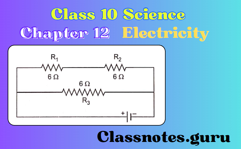
Question 7. Show how you would connect three resistors, each of resistance 60, so the combination has a resistance of 9 Ω2 4 Ω2.
Answer: Here, R1= R2 = R3 = 6 £2
When we connect Rt in series with the parallel combination of R2 and R3, as shown in the figure.
The equivalent resistance is
⇒ \(\mathrm{R}=\mathrm{R}_1+\frac{\mathrm{R}_2 \mathrm{R}_3}{\mathrm{R}_2+\mathrm{R}_3}\)
⇒ \(\begin{aligned}
& =6+\frac{6 \times 6}{6+6} \\
& =6+3=9 \Omega
\end{aligned}\)

When we connect a series combination of Rx and R2 in parallel with R3, as shown in
the figure, the equivalent resistance is
⇒ \(\begin{aligned}
R & =\frac{12 \times 6}{12+6}=\frac{72}{18} \\
& =4 \Omega
\end{aligned}\)
Question 8. Several electric bulbs designed to be used on a 220 V electric supply line, are rated 10 W. How many lamps can be connected in parallel across the two wires of the 220 line if the maximum allowable current is 5 A?
Answer: Resistance of each bulb, \(\mathrm{R}=\frac{\mathrm{V}^2}{\mathrm{P}}=\frac{(220)^2}{10}=4840 \Omega\)
Suppose n bulbs are needed to be connected in parallel with each other. Then their equivalent resistance Rp is given by
⇒ \(\frac{1}{\mathrm{R}_p}=\frac{1}{4840}+\frac{1}{4840}+\ldots(n \text { factors })=\frac{n}{4840}\)
or, \(\mathrm{R}_p=\frac{4840}{n} \Omega\)
Given V = 220 V,I = 5 A
By Ohm’s law
⇒ \(\begin{gathered}
\mathrm{R}_p=\frac{\mathrm{v}}{\mathrm{I}} \\
\frac{4840}{n}=\frac{220}{5}
\end{gathered}\)
or \(\begin{aligned}
& n=\frac{4840 \times 5}{220} \\
& n=110 .
\end{aligned}\)
Question 9. A hotplate ofan electric oven connected to a 220 Vline has two resistance coils A and B, each of 24 £2 resistance, which may be used separately, in series, or parallel. What are the currents in the three cases?
Answer: When the two coils A and B are used separately
R = 24 £2, V = 220 V
Current =\(\begin{aligned}
\mathrm{I} & =\frac{\mathrm{V}}{\mathrm{R}} \\
& =\frac{220 \mathrm{~V}}{24 \Omega} \\
& =9.167 \mathrm{~A}
\end{aligned}\)
When the two coils are connected in series,
R = 24 + 24 = 48 £2, V = 220 V
Current \(\begin{aligned}
\mathrm{I} & =\frac{\mathrm{V}}{\mathrm{R}} \\
& =\frac{220}{48} \\
& =4.58 \mathrm{~A} .
\end{aligned}\)
Current \(\begin{aligned}
I & =\frac{V}{R} \\
& =\frac{220}{48} \\
& =4.58 \mathrm{~A} .
\end{aligned}\)
When the two coils are connected in parallel,
⇒ \(\mathrm{R}=\frac{24 \times 24}{24+24}=12 \Omega, \mathrm{V}=220 \mathrm{~V}\)
Current, \(\begin{aligned}
\mathrm{I} & =\frac{\mathrm{V}}{\mathrm{R}}=\frac{220}{12} \\
& =18.33 \mathrm{~A}
\end{aligned}\)
Explain the following:
- Why is tungsten used almost exclusively for filament electric lamps?
- Why are the conductors of electric heating devices, such as bread toasters and electric
irons, made ofan alloy rather than a pure metal? - Why is the series arrangement not used for domestic circuits?
- How does the resistance of a wire vary with its area of cross-section?
- Why are copper and aluminium wires usually employed for electricity transmission?
Answer: This is because thin wire of tungsten has high resistance and high melting point (3410°C). When a current is passed through it, it becomes hot and emits light.
As compared to pure metals, alloys have higher resistivity. When a current is passed through the element made of alloy, a large amount of heat is produced.
The resistivity ofan alloy almost does not change with temperature. So an element of alloy does not readily get oxidised at high temperatures.
The series arrangement for house lights is not satisfactory due to the following reasons:
- Total voltage gets distributed over all the bulbs. So each bulb may not get sufficient power for its full operation.
- Total resistance becomes large, the current gets reduced. So the bulbs glow dimly.
- If one bulb blows, the entire circuit will be blown off.
- Electrons move more freely through a thick wire than through a thin wire. Also, there are more electrons free to move in a thick conductor than in a thin conductor. Hence, the resistance of a wire is inversely proportional to its area of cross-section.
- Copper and aluminium have low resistivities. When electricity is transmitted through copper and aluminium wires, the power losses in the form of heat are very small.
NCERT Class 10 Science Chapter 12: Electricity Questions and Answers
Question 10. A wire of length L and resistance R is stretched so that the length is doubled and the area of the cross-section is halved. How will it:
- Resistance change?
- Resistivity changes?
Answer: \(\text { – } \mathrm{R}=\rho \frac{l}{\mathrm{~A}}\)
Where R is the resistance and p is the resistivity
The initial length of the wire = l so its new length is l= 2l and the area of its cross-section = A/2
Now are A=A/2
Now, \(R=\rho \frac{L}{A} \text { and } R^{\prime}=\rho \frac{L^{\prime}}{A^{\prime}}\)
or R’ = 4R, i.e., the resistance increases to four times.
Question 11. Br Ba and B3 are three identical bulbs connected as shown in the figure. When all three bulbs glow, a current of 3 A is recorded by the ammeter A.
- What happens to the glow ofthe other two bulbs when the bulb Bt gets fused?
- What happens to the reading of A2, A3 and A when the bulb B2 gets fused1?

Answer: The glow of the bulbs B2 and B3 will remain the same.
A1 shows 1 ampere, A2 shows zero, A3 shows 1 ampere and A shows 2 ampere.
Question 12. Find the equivalent resistance ofthe following circuit:

Answer: Resistances of 2 Q each are connected in parallel.
Let Their Combined Restiance Be Rp1
So \(\frac{1}{\mathrm{R}_{\mathrm{P}_1}}=\frac{1}{2}+\frac{1}{2}=1\) Or Rp1 =1
Also, the resistance of 1 each is connected in parallel. let their combined resistance
So \(\frac{1}{\mathrm{R}_{\mathrm{P}_2}}=1+1=2\)
⇒\(\mathrm{R}_{\mathrm{P}_2}=\frac{1}{2}=0.5 \Omega\)
Equivalent resistance (R) of the circuit is given by
R = 3Q + 3Ω1+ RPΩ+ Rp2
= 6 Ω1 + 1 Q + 0.5 Ω1
= 7.5
Question 13. Two bulbs A and B are rated as 90 W- 120 V and 60 W- 120 V respectively. They connected in parallel across a 120 V source. Find the current in each bulb. Which bulb will consume more energy?
Answer: For the first bulb
Resistance, \(\mathrm{R}_1=\frac{\mathrm{V}^2}{\mathrm{P}_1}=\frac{(120)^2}{90}=160 \Omega\)
Current \(\mathrm{I}_1=\frac{\mathrm{V}}{\mathrm{R}}=\frac{120}{160}=0.75 \mathrm{~A}\)
For the second bulb,
Resistance \(\mathrm{R}_2=\frac{\mathrm{V}^2}{\mathrm{P}_2}=\frac{(120)^2}{60}=240 \Omega\)
Therefore Current \(\mathrm{I}_2=\frac{\mathrm{V}}{\mathrm{R}}=\frac{120}{240}=0.5 \mathrm{~A}\)
Bulb A will consume more energy because it has more power.
Key Concepts of Electricity NCERT Class 10 Science Chapter 12
Question 14. Find the current flowing through the following electric circuit

The series combination of 1 £2 and 3 £2 resistance is in parallel combination with 6 £2. Their equivalent resistance is
⇒ \(\frac{1}{\mathrm{R}_{\mathrm{P}}}=\frac{1}{6}+\frac{1}{3+1}=\frac{1}{6}+\frac{1}{4}=\frac{2+3}{12}\)
\(\mathrm{R}_{\mathrm{P}}=\frac{12}{5}=2.4 \Omega\)Now, 3.6 2.4 and 3 are in series, their equivalent resistance be Rs=R1+R2+R3=3.6+2.4+3=9
Hence, the current flowing through the circuit is
⇒\(\mathrm{I}=\frac{\mathrm{V}}{\mathrm{R}}=\frac{4.5}{9}=\frac{45}{90}=\frac{1}{2}=0.5 \mathrm{~A}\)
Question 15. Two lamps, one rated 100 W at 220 V, and the other 60 W at 220 V, are connected in parallel to a 220 V supply. Find the current drawn from the supply line.
Answer: Resistance of first lamp = Rt Resistance of second lamp = R2 We know that
⇒ \(\begin{aligned}
& \mathrm{R}=\frac{\mathrm{V}^2}{\mathrm{P}} \\
& \mathrm{R}_1=\frac{220 \times 220}{100}=484 \Omega \\
& \mathrm{R}_2=\frac{220 \times 220}{60}=\frac{2420}{3} \Omega
\end{aligned}\)
When R1 and R2 are connected in parallel.
⇒ \(\frac{1}{\mathrm{R}}=\frac{1}{\mathrm{R}_1}+\frac{1}{\mathrm{R}_2}\)
⇒ \(R=\frac{R_1 R_2}{R_1+R_2}=\frac{484 \times \frac{2420}{3}}{484+\frac{2420}{3}}\)
⇒ \(=\frac{484 \times \frac{2420}{3}}{484\left(1+\frac{5}{3}\right)}=\frac{2420 \times 3}{8 \times 3}=\frac{605}{2} \Omega\)
⇒ \(\mathrm{I}=\frac{\mathrm{V}}{\mathrm{R}}=\frac{220}{\frac{605}{2}}=\frac{220 \times 2}{605}\)
⇒ \(\begin{aligned}
\mathrm{I} & =\frac{8}{11} \mathrm{~A} \\
& =0.727
\end{aligned}\)
Question 16. The figure below shows three cylindrical copper conductors along with their face areas and lengths. Discuss in which geometrical shape the resistance will be highest.

Answer: For geometrical shape shown in
⇒ \(R_1=\rho \frac{L}{A}\)
⇒ \(\mathrm{R}_2=\rho \frac{2 \mathrm{~L}}{\mathrm{~A} / 2}=4\left(\rho \frac{\mathrm{L}}{\mathrm{A}}\right)=4 \mathrm{R}_1\)
⇒ \(R_3=\rho \frac{\mathrm{L} / 2}{2 \mathrm{~A}}=\frac{1}{4}\left(\rho \frac{\mathrm{L}}{\mathrm{A}}\right)=\frac{\mathrm{R}_1}{4}\)
Therefore, the resistance of the geometrical shape shown in Figure 2 will be the highest.
NCERT Class 10 Science Chapter 12: Electricity Numerical Problems
Question 17. A hotplate of an electric oven connected to a 220 Vline has two resistors A and B each of 22 Q. resistance. These resistors may be used separately, in series or in parallel. Find the current flowing in all the three cases.
Answer: Separately: Current \(\mathrm{I}=\frac{\mathrm{V}}{\mathrm{R}}=\frac{220}{22}=10 \mathrm{~A}\)
In series: \(\mathrm{R}=\mathrm{R}_1+\mathrm{R}_2=22+22=44 \Omega\)
therefore \(\mathrm{I}=\frac{\mathrm{V}}{\mathrm{R}}=\frac{220}{44}=5 \mathrm{~A}\)
In parallel:
⇒ \(\frac{1}{\mathrm{R}}+\frac{1}{\mathrm{R}_1}+\frac{1}{\mathrm{R}_2}=\frac{1}{22}+\frac{1}{22}\)
⇒ \(\begin{aligned}
& =\frac{1}{11} \\
R & =11 \Omega \\
\mathrm{I} & =\frac{\mathrm{V}}{\mathrm{R}} \\
& =\frac{220 \mathrm{~A}}{11 \Omega} \\
& =20 \mathrm{~A}
\end{aligned}\)
Question 18. A current ampere flows in a series circuit containing an electric lamp and a conductor of 5 Cl when connected to a 10 V battery. Calculate the resistance ofthe electric lamp. Now if the resistance of 10 Cl is connected in parallel with this series combination, what change (if any) in current flowing through the 5 Cl conductor and potential difference across the lamp will take place? Give reason.
Answer: Given current, I= 1A
- Resistance of conductor, R=5
- Voltage, v=10
- Resistance of lamp, R1=?
- Total resistance in the circuit,
⇒\(\begin{aligned}
\mathrm{R}_{\mathrm{T}} & =\frac{V}{\mathrm{~F}}=\frac{10}{1} \\
& =10 \Omega \\
\mathrm{R}_{\mathrm{L}} & =\mathrm{R}_{\mathrm{T}}-\mathrm{R}=10-5=5 \Omega
\end{aligned}\)

Potential difference across the lamp = IRL = 1 x 5 = 5 V
When 10 SI resistance is connected in parallel with total resistance Rp (RL + R = 10 £2),
then, the total resistance R in the circuit is given by

⇒ \(\begin{aligned}
\frac{1}{R^{\prime}} & =\frac{1}{10}+\frac{1}{R_T}=\frac{1}{10}+\frac{1}{10}=\frac{2}{10}=\frac{1}{5} \\
R & =5 \Omega
\end{aligned}\)
Current Through The circuit
⇒ \(I^{\prime}=\frac{V}{R^{\prime}}=\frac{10}{5}=\mathbf{2 A}\)
Since, 10 Q and RT (10 SI) are in parallel, current through \(R_T \text { is } \frac{I^{\prime}}{2}=\frac{2}{2}=1 \mathrm{~A}\)
Thus, Current Through Lamp And Conductor Of 5 In series In 1A. Also PB Across LAmp
⇒ \(\begin{aligned}
& =\frac{I^{\prime}}{2} \times 5=1 \times 5 \\
& =5 \mathrm{~V}
\end{aligned}\)
Question 19. The figure shows that B1, B2 and B3 are three identical bulbs connected. When all three bulbs glow, a current of 3A is recorded by the ammeter A.
- What happens to the glow ofthe other two bulbs when the bulb B: gets fused?
- What happens to AV A2, A3, and A reading when the bulb B2 gets fused?

3. How much power is dissipated in the circuit when all three bulbs glow together?
Answer: Resistance of combination of three bulbs in parallel \(\mathrm{R}_{e q}=\frac{V}{\mathrm{I}}=\frac{4.5}{3}=1.5 \Omega\)
If R is the resistance of each wire, then \(\frac{1}{\mathrm{R}_{e q}}=\frac{1}{\mathrm{R}}+\frac{1}{\mathrm{R}}+\frac{1}{\mathrm{R}} \text { or } \frac{1}{\mathrm{R}_{e q}}=\frac{3}{\mathrm{R}}\)
or \(\mathrm{R}=3 \mathrm{R}_{e q}=3+1.5=4.5 \Omega\)
Current in each bulb \(\begin{aligned}
I & =\frac{\mathrm{V}}{\mathrm{R}}=\frac{4.5 \Omega}{4.5 \Omega} \\
& =1 \mathrm{~A}
\end{aligned}\)
- When bulb B gets fused, the currents B2 and B3 remain the same i.e., I2 = I3 = 1 A because the voltage across the B2 and B3 bulbs remains the same, so their glow remains unaffected.
- When bulb B2 gets fused, the current in B2 becomes zero and the current in Bx and B3 remains 1 A. Because the voltage across Bx and B3 bulbs remains the same.
- Total current 7 = /1 + /2+/3 =l + 0 +l = 2A
- Current in ammeter, A2 = 0
- Current in ammeter, A3 = 1 A
- Current in ammeter, A1 = 1 A
- Current in ammeter, A = 2 A
- When all the three bulbs are connected
Power dissipated, \(\begin{aligned}
\mathrm{P} & =\frac{\mathrm{V}^2}{\mathrm{R}_{e q}}=\frac{(4.5)^2}{1.5} \\
& =13.5 \mathrm{~W}
\end{aligned}\)
Question 20. Three incandescent bulbs of 100 W each are connected in series in an electric circuit. In another circuit, another set of three bulbs of the same wattage are connected in parallel to the same source.
Will the bulb in the two circuits glow with the same brightness? Justify your answer. Now let one bulb in both the circuits get fused. Will the rest of the bulbs continue to shine in each circuit? Give reason.
Answer: The resistance of the bulbs in series will be three times the resistance of a single bulb. Therefore, the current in the series combination will be one-third as compared to the current in each bulb in a parallel combination. The parallel combination of bulbs will glow more brightly.
The bulbs in a series combination will stop glowing as the circuits break and the current is zero. However, the bulbs in parallel combination shall continue to glow with the same brightness.
Question 21. State Ohm’s law. How can it be verified experimentally? Does it hold good under all conditions? Comment.
Answer: Ohm’s law states that the electric current flowing through a conductor is directly proportional to the potential difference applied across its ends, provided the physical conditions such as temperature remain unchanged.
If V is the potential difference applied across the ends of a conductor through which the current flows, then according to Ohm’s law
⇒ \(\begin{aligned}
& \mathrm{V} \propto \mathrm{I} \Rightarrow \mathrm{V}=\mathrm{IR} \\
& \mathrm{I}=\frac{\mathrm{V}}{\mathrm{R}}
\end{aligned}\)
where R is the constant of proportionality called resistance of the conductor at a given temperature. The experimental set of Boehm’s law is made as the circuit shown below in the figure, consisting of a nichrome wire XY, an ammeter (A), A voltmeter (V) and four cells of 1.5 V each.

The reading in the ammeter A for the current and reading of the voltmeter V for the potential difference across the nichrome wire XY is measured and recorded in the table given below.
First by using only one cell and then by the two, three and four cells in successive readings.

Calculating the ratio of V to for each pair of potential difference V and current I. A graph is plotted between V and 7 and the nature ofthe graph is observed as shown here.
The same value for V/I is obtained corresponding to one, two, three and four cells in successive readings.
Also, the V-1 graph is obtained as a straight line that passes through the origin. This law is only valid for ohmic conductors, for example, metals. Thus, V/I is a constant, i.e., V I This verifies Ohm’s law.
Ohm’s law does not hold good under all conditions as it is not a fundamental law of nature like Newton’s law. It is obeyed by metallic = conductors only when physical conditions like temperature etc. kept unchanged. It is not obeyed by a lamp filament, junction diode, 0 thermistor etc. These are called non-ohmic conductors.

NCERT Class 10 Science Chapter 12: Electricity Key Terms
Question 22. What is the electrical resistivity of material1? What is its unit? Describe an experiment to study the factors on which the resistance of conducting wire depends.
Answer: The electrical resistivity of a material is defined as the resistance of a conductor made of that material of unit length and unit cross-sectional area. Its SI unit is Ohm metre (Q m).
⇒ \(\mathrm{R}=\rho \frac{l}{\mathrm{~A}} \Rightarrow \rho=\frac{\mathrm{RA}}{l}\)
(where, A = 2 m2 1m)
Consider an electric circuit consisting of a cell, an ammeter, a nichrome wire length (marked to 4) and a plug key as shown below.

Unplug the key and note the ammeter. Replace the nichrome wire with another nichrome wire of the same thickness but twice the length, i.e., 21 at point 2. Again note the reading. Now, replace the wire with a thicker nichrome wire of the same length (marked 3). A thicker wire has a larger cross-sectional area.
Again note down the current through the circuit. Replace nichrome wire with copper wire of the same length and same area of cross-section at point 4. Note the value of the current. Notice the difference in the current in all cases. When the length ofthe wire is doubled, then the ammeter reading decreases to halfits the previous value, i.e., the current through the wire is halved.
Since the resistance ofthe wire \(\mathrm{R}=\frac{\mathrm{V}}{l}\) there is doubled which implies R °cL when the microphone wire is replaced by a thicker one of the same material and length, the current in the wire increases which means that the resistance ofthe thicker wire (3) is less than that of the thinner wire (1). This implies \(R \propto \frac{1}{\mathrm{~A}}\)
When the nichrome wire is replaced by a copper wire (4) of the same length and cross-sectional area, then the current recorded by the ammeter is greater. This means that the resistance of a copper wire is less than that of a nichrome wire of the same dimensions, i.e., the resistance of the wire depends on the nature of its material.
Question 23. How will you infer with the help ofan experiment that the same current flows through every part ofthe circuit containing three resistors in series connected to a battery?
Answer: Let the experimental set-up comprise three resistors R1, R2 and R3 of three different values such as In, 2n and 3n which are connected in series. Connect them with a battery of 6 V, an ammeter and plug in a key.
The key K is closed and the ammeter reading is recorded. Now the position of the ammeter is changed to anywhere between the resistors again, the ammeter reading is recorded each time.
It’s observed that there was an identical reading each time, which shows that the same current flows through every part ofthe circuit containing three resistors in series connected to a battery.
Question 24. How will you conclude that the same potential difference? (voltage) exists across three resistors connected in a parallel arrangement to a battery? (PBQ)
Answer: The experimental set-up comprises three resistors R1, R2 and R3) which are joined in parallel combination and connected with a battery, an ammeter (A), a voltmeter (V) and a plug key K, as shown in the figure. The key K is closed and the voltmeter and ammeter readings are recorded.

The key K is opened and now remove the ammeter and voltmeter from the circuit and insert the voltmeter Vin parallel with Rx, and the ammeter in series with the resistor R1; as shown in the figure. Again, the voltmeter and ammeter readings are recorded.

Similarly, measuring the potential differences across resistors R2 and R3, it is found that the voltmeter gives identical readings which leads to conclude that the voltage or potential difference across each resistor is the same and equal to the potential difference across the combination.
Question 25. What is Joule’s heating effect? How can it be demonstrated experimentally? List its four applications in daily life.
Answer: The heating effect of current is defined by Joule’s law of heating H=I2RT
It is also called Ohmic heating and resistive heating. In a conductor, when an electric field is applied across its ends, the free electrons available start drifting opposite to the direction ofthe electric field.
These electrons collide with the atoms which have lost the electrons. As a result of these collisions some energy of the electrons is transferred to the atoms which vibrate violently as they gain energy. Thus, heat is developed in the conductor.
- Four Applications
- Room Heater
- Electric Bulb
- Electric Iron
- Electric Fuse
Question 26. Find out the following in the electric circuit given in the figure.

- The effective resistance of two 8 Q. resistors in the combination
- Current flowing through 4 Q resistor
- The potential difference across 4 £2 resistor
- The power dissipated in a 4 Q resistor
- Difference in ammeter readings, if any.
Answer: Since two 8£2 resistors are in parallel,
rP Is Given By
⇒ \(\frac{1}{\mathrm{R}_p}=\frac{1}{\mathrm{R}_1}+\frac{1}{\mathrm{R}_2}=\frac{1}{8}+\frac{1}{8}=\frac{1}{4} \Omega\)
Total resistance in the circuit, \(\mathrm{R}=4 \Omega+\mathrm{R}_p=8 \Omega\)
Current Through circuit \(I=\frac{\mathrm{V}}{\mathrm{R}}=\frac{8}{8}=1 \mathrm{~A}\)
V = IR = 1 x 4 = 4 V
P = I2R = l2 x 4 = 4 W
No difference in ammeter reading.
Question 27. In the given figure, A, B and C are three ammeters. The ammeter reads 0.5 A. (All the ammeters have negligible resistance.) Calculate The readings in the ammeters A and C. the total resistance ofthe circuit.

Answer: The current in the ammeter B ami C is inversely proportional to the value of resistance in the parallel branch. Therefore,
⇒ \(\frac{\text { Reading of ammeter } \mathrm{C}}{\text { Reading of ammeter } \mathrm{B}}=\frac{6}{3}=2\)
Therefore, reading of ammeter C = 2 x 0.5 = 1.0 A
Hence, reading of ammeter A = (0.5 + 1.0) A = 1.5 A
Let the total resistance of the circuit be R.
Therefore. R = 2 + Rp, where
⇒ \(\frac{1}{\mathrm{R}_{\mathrm{P}}}=\frac{1}{3}+\frac{1}{6}=\frac{1}{2} \text { or } \mathrm{R}_{\mathrm{P}}=2 \text { ohm }\)
Therefore, R = 2 + 2 = 4 ohm
NCERT Solutions for Chapter 12: Electricity – Class 10 Science
Question 28. Which of the graphs is (are) correctly labelled in terms ofthe words ‘series and ‘parallel’1? Justify your answer.
Answer: In a series combination for a given voltage, the current is less as compared to that in a parallel Combination. Therefore, both the graphs are labelled correctly.
- Which particles constitute an electric current in a metallic conductor?
- Define the SI unit of current.
Answer: The flow of electric charges across a cross-section of a conductor constitutes an electric current.
An electric circuit is a continuous and closed conducting path along which an electric current flows.
Electrons
If one coulomb of charge flows through any conductor section in one second, then the current through it is said to be one ampere.
Question 29. Sanchi’s mother was cooking in the kitchen for guests. Sanchi saw her father had plugged in a microwave hot plate at the same point. She immediately switched off the plug removed all the plugs and re-plugged them in separate individual plugs.
What occurs when we use too many devices plugged into one PowerPoint?
- What is the power of a device?
- What value do we get from the above act?
Answer:
- Overloading occurs.
- Power ofan electric device is the amount of electric current used within a unit of time.
- Value of awareness and responsibility.
Question 30. The electrons in a metallic conductor move only if there is a difference in electric pressure called the potential difference along the conductor. The chemical action within a cell generates the potential difference across its terminals. When the cell is connected to a circuit element, the potential difference sets the electrons in motion and produces an electric current.
- Name a device that helps to maintain the potential difference.
- What is meant by a potential difference of 1 volts?
- Would the electrons move from higher potentials to lower potentials or vice-versa?
- Name the device which is used to measure the potential difference between two points.
Answer:
- Battery
- The potential difference between the two points is 1 volt if one joule of work is done in moving a positive charge of one coulomb from one point to the other point.
- Electrons move from lower potentials to higher potentials.
- Voltmeter
NCERT Class 10 Science Chapter 12: Electricity Key Terms
Question 31. Ahmed noticed in a hotel that around 50 bulbs of 100 watts were glowing. He calculated the cost of electricity consumed in an hour and told the hotel owner to reduce the expenditure by using CFL bulbs.
- What would be the consumption of 50 bulbs in an hour unit amounts?
- What is the full form of CFL?
- What qualities should we learn from Ahmed?
Answer: Cost of 50 bulbs in 1 hour:
- 50 bulbs x 100 watt = 5000 watt = 5 kWh
- 1 unit cost =5 = 5×5 =
- CFL stands for compact fluorescent lamp.
- Responsible behaviour, Aware Citizen, And Analyser.