NEET Physics Class 12 Notes For Chapter 6 Electromagnetic Induction

Chapter 6 Electromagnetic Induction

1. Magnetic Flux

The concept of magnetic lines of force was first proposed by Faraday. Faraday tried to provide the lines of force a real form assuming them as stretched rubber bands.

  • In modern physics, the concept of magnetic lines of force is used in visualization or explanation of principles only.
  • The tangent drawn at any point on a line of force in a magnetic field shows the direction of the magnetic field at that point and the density of lines of force, i.e., the number of lines of force crossing normally a unit area indicates the intensity of the magnetic field.
  • The lines of force in a uniform magnetic field are parallel straight lines equidistant from each other.
  • Where the lines of force are near each other, B is higher and where the lines of force are far apart, B is lesser.
  • The number of lines of force crossing a given surface is called flux from that surface.
  • Suppose it is generally represented by Φ. Flux is a property of a vector field. If the vector field is a magnetic field, then the flux is called magnetic flux.

Electromagnetic Induction Notes for NEET Physics Class 12

The magnetic flux crossing a certain area is equal to the scalar product of the vector field \((\vec{B})\) and the vector area \((\overrightarrow{\mathrm{dA}})\), that is

Magnetic flux \(\mathrm{d} \phi=\overrightarrow{\mathrm{B}} \cdot \overrightarrow{\mathrm{dA}}=\mathrm{BdA} \cos \theta\)

where θ is the angle between the vector field \((\vec{B})\) and the vector area \(\overrightarrow{\mathrm{dA}}\).

Φ = ∫ \(\overrightarrow{\mathrm{B}} \cdot \overrightarrow{\mathrm{dA}}\)

For a uniform magnetic field \((\vec{B})\) and plane surface \((\vec{A})\) = \((\vec{B})\).\((\vec{A})\) = BA cosθ

(Note: In real sense, area is a scalar quantity, but it can be treated as whose direction is in the direction of perpendicular pointing outward from the surface)

Magnetic flux is a scalar quantity.

If a plane surface of area A is imagined in a uniform magnetic field \((\vec{B})\), then

(1)when a surface is perpendicular to the magnetic field, the lines of force crossing that area, i.e., the magnetic flux is

NEET Physics Class 12 Chapter 6 Electromagnetic Induction Surface Is Perpendicular To The Magnetic Field

Φ= BA because θ = 0, cos θ = 1

(2) If the surface is parallel to the field, then

NEET Physics Class 12 Chapter 6 Electromagnetic Induction Surface Is Parallel To The Field

Electromagnetic Induction Notes for NEET Physics Class 12

θ = 90°, cos θ = 0

∴ Φ= BA cos 90 = 0

(3) when the normal to the surface makes an angle θ with the magnetic field, the magnetic flux is Φ = BA cosθ

Suppose the magnetic field is not uniform and the surface is in no plane. In that case, the element \(\overrightarrow{\mathrm{dA}}\) of the surface may be assumed as plane and magnetic field \((\vec{B})\) may also be assumed as uniform over his element.

Thus the magnetic flux coming out from this element is \(\mathrm{d} \phi=\overrightarrow{\mathrm{B}} \cdot \overrightarrow{\mathrm{dA}}\)

Hence magnetic flux coming out from the entire surface \(\phi=\int_s \vec{B} \cdot \overrightarrow{d A}\)

NEET Physics Class 12 Chapter 6 Electromagnetic Induction Magnetic Flux Coming Out From Entire Surface

For a closed surface the vector area element pointing outward is positive and the vector area element pointing inward is negative.

Magnetic lines of force are closed curves because free magnetic poles do not exist. Thus for a closed surface whatever the number of lines of force entering it, the same number of lines of force come out from it.

As a result for a closed curve \(\phi=\int_{\mathrm{s}} \overrightarrow{\mathrm{B}} \cdot \overrightarrow{\mathrm{dA}}=0 \text { or } \quad \nabla \cdot \vec{B}=0\)

Thus the net magnetic flux coming out of a closed surface is equal to zero.

For a normal plane surface in a magnetic field

Φ= BA

Hence B = \(\frac{\phi}{\mathrm{A}}\)

Thus the magnetic flux passing through normally from the surface of a unit is equal to magnetic induction B.

Therefore \(\frac{\phi}{\mathrm{A}}\) is also called flux density.

Unit Of Magnetic Flux – In the M.K.S. system the unit of magnetic flux is Weber (Wb) and in the C.G.S. system, the unit of magnetic flux is Maxwell.

1 weber = 108 maxwell

The M.K.S unit of flux density or magnetic induction is Weber/m2. It is also called tesla.

1 tesla = 1 weber/m2

The C.G.S unit of magnetic flux density is gauss.

1 gauss = 1 maxwell/cm8

1 tesla = 1 weber/m2 = 104 gauss

Dimensions Of Magnetic Flux: Φ = BA

∴ \([\phi]=\frac{N}{A-m} \times m^2=\frac{N-m}{A}=\frac{\left(kg-m-s^2\right) \times m}{A}\)

= \(k g-m^2-s^2-A-1 \quad=M^1 L^2 T-2 A-1\)

1. Magnetic Flux Solved Examples

Example 1. The plane of a coil of area 1m2 and having 50 turns is perpendicular to a magnetic field of 3 x 10⁻⁵ weber/m2. The magnetic flux linked with it will be

  1. 1.5 x 10⁻³ weber
  2. 3 x 10⁻⁵ weber
  3. 15 x 10-5 weber
  4. 150 weber

Solution:

Φ = NBA cosθ

but N = 50, B = 3 x 10⁻⁵ wb/m2,

A = 1m2, θ = 0 or Φ = NBA

= 50 × 3 ×10-5× 1

= 150 × 10-5 weber

∴ Answer will be (1)

Example 2. Consider the fig. A uniform magnetic field of 0.2 T is directed along the +x axis. Then what is the magnetic flux through the top surface of the figure?

NEET Physics Class 12 Chapter 6 Electromagnetic Induction Uniform Magnetic Field Directed Along X Axis

  1. Zero
  2. 0.8 Wb
  3. 1.0m Wb
  4. -1.8m Wb

Solution:

The magnetic flux is Φ = BA cosθ

for the top surface, the angle between normal to the surface and the x-axis is θ = 60°, and B = 0.2 T, A = 10 x 10 x 10-4 m2

Thus Φ = 0.2 x 10⁻² x cos (60)= 10-3 Wb.

The correct answer is thus (3)

NEET Physics Chapter 6 Electromagnetic Induction Study Notes

1.1 Faraday’s Laws Of Electromagnetic Induction

When magnetic flux passing through a loop changes with time or magnetic lines of force are cut by a conducting wire then an emf is produced in the loop or in that wire. This emf is called induced emf.

If the circuit is closed then the current will be called induced current.

magnetic flux = \(\int \overrightarrow{\mathrm{B}} \cdot \mathrm{d} \overrightarrow{\mathrm{s}}\)

The magnitude of induced emf is equal to the rate of change of flux w.r.t. time in the case of a loop.

In the case of a wire, it is equal to the rate at which magnetic lines of force are cut by a wire

E = \(-\frac{\mathrm{d} \phi}{\mathrm{dt}}\)

(–) the sign indicates that the emf will be induced in such a way that it will oppose the change of flux.SI unit of magnetic flux = Weber.

1.1 Faraday’s Laws Of Electromagnetic Induction Solved Examples

Example 1. A coil is placed in a constant magnetic field. The magnetic field is parallel to the plane of the coil as shown in the figure. Find the emf induced in the coil.

NEET Physics Class 12 Chapter 6 Electromagnetic Induction Coil Is Placed In A Constant Magnetic Field

Solution:

Φ = 0 (always) since the area is perpendicular to the magnetic field.

∴ emf = 0

Example 2. Find the emf induced in the coil shown in the figure. The magnetic field is perpendicular to the plane of the coil and is constant.

NEET Physics Class 12 Chapter 6 Electromagnetic Induction Magnetic Field Is Prependicular To The Plane Of The Coil And Is Constant

Solution:

Φ = BA (always) = const.

∴ emf = 0

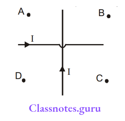
Example 3. Find the direction of the induced current in the coil shown in the figure. The magnetic field is perpendicular to the plane of the coil and it is increasing with time.

NEET Physics Class 12 Chapter 6 Electromagnetic Induction Direction Of Induced Current In The Coil

Solution:

Inward flux is increasing with time. To oppose it, an outward magnetic field should be induced.

Hence current will flow anticlockwise.

Example 4. Shows a coil placed in a decreasing magnetic field applied perpendicular to the plane of the coil. The magnetic field is decreasing at a rate of 10T/s. Find out the current in magnitude and direction

NEET Physics Class 12 Chapter 6 Electromagnetic Induction Coil Placed In Decreasing Magnetic Field Applied Perpendicular To The Plane Of Coil

Solution: Φ = B.A

emf = A . \(\frac{\mathrm{d B}}{\mathrm {d t}}\) = 2 x 10 = 20 v

∴ i = 20/ 5 = 4 amp.

From Lenz’s law, the direction of the current will be anticlockwise.

Example 5. Figure shows a long current carrying wire and two rectangular loops moving with velocity v. Find the direction of current in each loop.

NEET Physics Class 12 Chapter 6 Electromagnetic Induction Long Current Carrying Wire And Two Rectangular Loops Moving With Velocity

Solution:

In loop (1) no emf will be induced because there is no flux change.

In loop (2) emf will be induced because the coil is moving in a region of decreasing magnetic field inward in direction.

Therefore to oppose the flux decrease in inward direction, current will be induced such that its magnetic field will be inwards. For this direction the current should be clockwise.

2. Lenz’s Law (Conservation Of Energy Principle)

According to this law, emf will be induced in such a way that it will oppose the cause which has produced it. The figure shows a magnet approaching a ring with its north pole towards the ring.

NEET Physics Class 12 Chapter 6 Electromagnetic Induction Lenzs Law Conservation Of Energy Principal

We know that magnetic field lines come out of the north pole and magnetic field intensity decreases as we move away from the magnet. So the magnetic flux (here towards left) will increase with the approach of the magnet.

This is the cause of flux change. To oppose it, the induced magnetic field will be towards the right. For this, the current must be anticlockwise as seen by the magnet.

If we consider the approach of the North Pole to be the cause of flux change, Lenz’s law suggests that the side of the coil towards the magnet will behave as the North Pole and will repel the magnet.

We know that a current-carrying coil will behave like a North Pole if it flows anticlockwise. Thus as seen by the magnet, the current will be anticlockwise.

If we consider the approach of the magnet as the cause of the flux change, Lenz’s law suggests that a force opposite to the motion of the magnet will act on the magnet, whatever the mechanism.

Lenz’s law says that if the coil is set free, it will move away from the magnet because in doing so it will oppose the ‘approach’ of the magnet.

If the magnet is given some initial velocity towards the coil and is released, it will slow down. It can be explained as the following.

The current induced in the coil will produce heat. From energy conservation, if heat is produced there must be an equal decrease of energy in some other form, here it is the kinetic energy of the moving magnet.

Thus the magnet must slow down. So we can justify that Lenz’s law is the conservation of energy principle.

Class 12 NEET Electromagnetic Induction Notes

2.1 Induced Emf, Current And Change In A Circuit

If e.m.f induced in a circuit is E and the rate of change of magnetic flux is dΦ/dt, then from Faraday’s and Lenz’s law

E \(\propto-\left(\frac{\mathrm{d} \phi}{\mathrm{dt}}\right)\) or \(\mathrm{E}=-\mathrm{K}\left(\frac{\mathrm{d} \phi}{\mathrm{dt}}\right)\) where K is constant, equal to one.

Thus \(E=-\left(\frac{d \phi}{d t}\right)\)

If there are \(\mathrm{N}\) turns in the coil, then induced e.m.f will be

E = \(-N\left(\frac{d \phi}{d t}\right)\)

If the magnetic flux linked with the circuit changes from \(\phi_1 \quad to \quad \phi_2\), in time t, then induced e.m.f will be

E = \(-N\left(\frac{d \phi}{d t}\right)=-N\left(\frac{\phi_2-\phi_1}{\mathrm{t}}\right)\)

If the resistance of the circuit is R, then the current induced in the circuit will be

I = \(\frac{\mathrm{E}}{\mathrm{R}}=-\frac{\mathrm{N}\left(\phi_2-\phi_1\right)}{t R} \text { ampere } \quad=-\frac{\mathrm{N}}{\mathrm{R}}\left(\frac{\mathrm{d} \phi}{\mathrm{dt}}\right) \text { ampere }\)

Induced current depends upon

  1. The resistance of the circuit \(\mathrm{I} \propto \frac{1}{\mathrm{R}}\)
  2. The rate of change of magnetic flux \(\mathrm{I} \propto\left(\frac{\mathrm{d} \phi}{\mathrm{dt}}\right)\)
  3. The number of turns \((\mathrm{N}) ; \mathrm{I} \propto \mathrm{N}\)

If R = ∞, that is, the circuit is open, then the current will not flow and if the circuit is closed, then the current will flow in the circuit.

If change dq flows in the circuit in time dt, then the induced current will be

I = \(\left(\frac{d q}{d t}\right)\) or dq = I dt but \(I=\frac{1}{R}\left(\frac{d \phi}{d t}\right)\)

∴ dq = \(\frac{1}{R}\left(\frac{d \phi}{d t}\right) d t=\frac{1}{R} d \phi\) or \(q=\int \frac{d \phi}{R}=\frac{\phi_2-\phi_1}{R}\)

If N is the number of turns, then \(\mathrm{dq}=\frac{\mathrm{Nd} \phi}{R}, \mathrm{q}=\frac{\mathrm{N}\left(\phi_2-\phi_1\right)}{R}\)

The charge flowing due to induction does not depend upon the time but depends upon the total change in the magnetic flux. It does not depend upon the rate or time interval of the change in magnetic flux.

Whether the change in magnetic flux is rapid or slow, the charge induced in the circuit will remain the same.

Thus \(\mathrm{q} \propto \mathrm{d} \phi \text { or } \mathrm{q} \propto\left(\phi_2-\phi_1\right)\)

The induced charge depends upon the resistance of the circuit, i.e., q ∝ 1/R

If R = ∞ or the circuit is open, q = 0 that is charge will not flow in the circuit.

If R≠ ∞ or circuit is closed, then q ≠ 0, that is, the induced charge will flow in the circuit The e.m.f induced in the circuit does not depend upon the resistance of the circuit.

The e.m.f induced in the circuit depends upon the following factors –

  1. Number of turns (N) in the coil,
  2. Rate of change of magnetic flux,
  3. Relative motion between the magnet and the coil,
  4. The cross-sectional area of the coil,
  5. The magnetic permeability of the magnetic substance or material placed inside the coil.

2.2 Fleming’s Right Hand Rule

This law is used for finding the direction of the induced e.m.f or current.

According to this law, if we stretch the right-hand thumb and two nearby fingers perpendicular to one another and the first finger points in the direction of the magnetic field and the thumb in the direction of motion of the conductor then the central finger will point in the direction of the induced current.

NEET Physics Class 12 Chapter 6 Electromagnetic Induction Flemings Right Hand Rule

2.3 Direction Of Induced Emf And Current (Applications Of Lenz’s Law)

If the current flowing in a coil appears anti-clockwise, then that plane of the coil will behave like an N-pole.

NEET Physics Class 12 Chapter 6 Electromagnetic Induction Current Flowing In A Coil Appears Anti Clockwise Then That Plane Of Coil Will Behave N Pole

If the current flowing in the coil appears clockwise, then that plane of the coil will behave like a S-pole.

NEET Physics Class 12 Chapter 6 Electromagnetic Induction Current Flowing In A Coil Appears Clockwise Then That Plane Of Coil Will Behave S Pole

NEET Physics Chapter 6 Electromagnetic Induction Study Notes

If the north pole of a magnet is moved rapidly towards the coil, then according to Lenz’s law the induced current will flow in the coil in such a direction as to oppose the motion of the magnetic happen only when the face of the coil towards the magnet behaves as a north pole, that is, the induced current will appear flowing in an anti-clockwise direction as seen from the side of the magnet.

Thus a force of repulsion will be produced between the magnet and the coil coming near each other which will oppose the motion of the magnet.

Hence some mechanical work has to be done to move the magnet near the coil against this opposing force and this work (mechanical energy) is converted into current (electrical energy)

NEET Physics Class 12 Chapter 6 Electromagnetic Induction Northpole Of Magnetic Is Moved Rapidly Towards Coil

On bringing a south pole towards a coil the current induced in the coil will appear to flow in a clockwise direction as observed from the side of the magnet and the face of the coil towards the magnet will behave as a south pole.

NEET Physics Class 12 Chapter 6 Electromagnetic Induction On Moving The North Pole Of A Magnet Away From The Coil The Current Induced In The Coil Will Appear Flowing Clockwise Direction

On moving the north pole of a magnet away from the coil the current induced in the coil will appear to flow in the clockwise direction as seen from the side of the magnet and the face of the coil towards the magnet will behave as a south pole.


NEET Physics Class 12 Chapter 6 Electromagnetic Induction South Pole Towards A Coil The Current Induced In The Coil Will Appear Flowing Clockwise Direction

On moving the south pole of a magnet away from the coil the current induced in the coil will appear to flow in the anticlockwise direction as seen from the side of the magnet and the face of the coil towards the magnet will behave like a north pole.

NEET Physics Class 12 Chapter 6 Electromagnetic Induction On Moving The South Pole Of A Magnet Away From The Coil The Current Induced In The Coil Will Appear Flowing In Anticlockwise Direction

If a magnet is allowed to drop freely through a copper coil, then an induced current will be produced in the coil. This current will oppose the motion of the magnet, as a result, the acceleration of the falling magnet due to gravity will be less than ‘g’.

If the coil is cut somewhere, then the emf will be induced in the coil only but current will not be induced. In the absence of induced current the coil will not oppose the motion of the magnet and the magnet will fall through the coil with the acceleration equal to g.

If a magnet is dropped freely in a hollow long metal cylinder, then the acceleration of the falling magnet will be less than gravitational acceleration.

As the magnet keeps on falling inside a tube, its acceleration will continue to decrease and after traversing a certain distance the acceleration will become zero. Now the magnet will fall with constant velocity. This constant velocity is called terminal velocity.

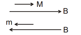
If a current-carrying coil is brought near another stationary coil, then the direction of induced current in the second coil will be in the direction of current in the moving coil.

NEET Physics Class 12 Chapter 6 Electromagnetic Induction If A Current Carrying Coil Is Brought Near Another Stationary Coil

If a current-carrying coil is taken away from a stationary coil, then the direction of induced current in the second coil will be opposite to the direction of current in the moving coil.

NEET Physics Class 12 Chapter 6 Electromagnetic Induction If A Current Carrying Coil Is Taken Away From A Stationary Coil

In the coils arranged in the following way, when the key K connected to the circuit of the primary coil, is pressed, an induced current is produced in the secondary coil.

The direction of the induced current in the secondary coil is opposite to the direction of the current in the primary coil. (From Lenz’s law) When the key is opened, then the current in the primary coil is reduced to zero but current is induced in the secondary coil.

The direction of this induced current is the same as the direction of the current in the primary coil. (Form Lenz’s law).

NEET Physics Class 12 Chapter 6 Electromagnetic Induction The Direction Of This Induced Current IS Same As The Direction Of Current In The Primary Coil

When current is passed through a coil, the current flowing through the coil changes. As a result, the magnetic flux linked with the coil changes. Due to this, a current is induced in the coil. If the current induced in the coil flows in the opposite direction of the applied current.

NEET Physics Class 12 Chapter 6 Electromagnetic Induction Current Flowing In The Coil Is Decreased

If the current flowing in the coil is decreased, then the current induced in the coil flows in the direction of the applied current so as to oppose the decrement of the applied current.

Two coils A and B are arranged as shown in the figure. On pressing the key K current flows through coil A in the clockwise direction and the current induced in coil B will flow in the anticlockwise direction. (From Lenz’s law)NEET Physics Class 12 Chapter 6 Electromagnetic Induction The Current Induced In The Coil B Will Flow In The Clockwise Direction

On opening the key K the current flowing through coil A will go on decreasing. Thus the current induced in coil B will flow in the clockwise direction.

If current flows in a straight conductor from A to B as shown in the figure, then the direction of current induced in the loop placed near it will be clockwise. (From Lenz’s law).

NEET Physics Class 12 Chapter 6 Electromagnetic Induction Direction Of Current Induced In The Loop Placed Near It Will Be Clockwise

Three identical circular coils A, B and C are arranged coaxially as shown in the figure. The coils A and C carry equal currents as shown. Coils B and C are fixed in position.

If coil A is moved towards B, then the current induced in coil B will be in a clockwise direction because the direction of the current induced in coil B will oppose the motion of coil A.

(The face of A towards B is the south pole, then the face of B towards A is the south pole). There is no relative motion between B and C so current will not be induced in coil B due to coil C.

NEET Physics Class 12 Chapter 6 Electromagnetic Induction Three Identical Circular Coils ABC Are Arranged Coaxially

3. Motional Emf

We can find emf induced in a moving rod by considering the number of lines cut by it per sec assuming there are ‘B’ lines per unit area. Thus when a rod of length l moves with velocity v in a magnetic field B, as shown, it will sweep area per unit time equal to Iv and hence it will cut B l v lines per unit time.

NEET Physics Class 12 Chapter 6 Electromagnetic Induction emf Induced Between The Ends Of The Rod

Hence emf induced between the ends of the rod = Bvl

Also emf= \(\frac{\mathrm{d} \phi}{\mathrm{dt}}\).

Here Φ denotes flux passing through the area, swept by the rod. The rod sweeps an area equal to A/dt in time interval dt. Flux through this area = BA/dt.

Thus \(\frac{\mathrm{d} \phi}{\mathrm{dt}}=\frac{\mathrm{B} \ell \mathrm{vdt}}{\mathrm{dt}}=\mathrm{Bv} \ell\)

NEET Physics Class 12 Chapter 6 Electromagnetic Induction Rod Is Moving It Will Sweep Area Per Unit Time

If the rod is moving as shown in the following figure, it will sweep area per unit time = v l sinθ and hence it will cut B v l sinθ lines per unit time.

Thus emf = Bvl sinθ.

3.1 Explanation Of Emf Induced In Rod On The Basis Of Magnetic Force

If a rod is moving with velocity v in a magnetic field B,  as shown, the free electrons in a rod will experience a magnetic force in a downward direction and hence free electrons will accumulate at the lower end and there will be a deficiency of free electrons and hence a surplus of positive charge at the upper end.

These charges at the ends will produce an electric field in a downward direction which will exert an upward force on the electron.

If the rod has been moving for quite some time enough charges will accumulate at the ends so that the two forces qE and qvB will balance each other. Thus E = v B.

NEET Physics Class 12 Chapter 6 Electromagnetic Induction EMF Induced In Rod On The Basis Of Magnetic Force

VP – VQ= V B l

The moving rod is equivalent to the following diagram, electrically.

NEET Physics Class 12 Chapter 6 Electromagnetic Induction The Moving Rod Is Equivalent

Shows a closed coil ABCA moving in a uniform magnetic field B with a velocity v. The flux passing through the coil is a constant and therefore the induced emf is zero.

NEET Physics Class 12 Chapter 6 Electromagnetic Induction The Flux Passing Through The Coil Is A Consant And Induced emf Is Zero

Now consider rod AB, which is a part of the coil. Emf induced in the rod =B L v

Suppose the emf induced in part ACB is E, as shown.

NEET Physics Class 12 Chapter 6 Electromagnetic Induction emf Induced In Part ACB IS E

Since the emf in the coil is zero, Emf (in ACB) + Emf (in BA) = 0

or -E + vBL = 0 or E = vBL

Thus emf induced in any path joining A and B is the same, provided the magnetic field is uniform. Also, the equivalent emf between A and B is BLv (here the two emf’s are in parallel)

3.1 Explanation Of Emf Induced In Rod On The Basis Of Magnetic Force Solved Examples

Example 1. Find the emf induced in the rod in the following cases. The figures are self-explanatory.

NEET Physics Class 12 Chapter 6 Electromagnetic Induction EMF Induced In The Rod Following Cases

Solution:

(1)here \(\overrightarrow{\mathrm{v}} \| \overrightarrow{\mathrm{B}} \text { so } \overrightarrow{\mathrm{v}} \times \overrightarrow{\mathrm{B}}=0\)

emf = \(\vec{\ell} \cdot(\overrightarrow{\mathrm{v}} \times \overrightarrow{\mathrm{B}})=0\)

(2)here \(\overrightarrow{\mathrm{v}} \| \vec{\ell}\)

so emf = \(\vec{\ell} \cdot(\overrightarrow{\mathrm{v}} \times \overrightarrow{\mathrm{B}})=0\)

(3)here \(\overrightarrow{\mathrm{B}} \| \vec{\ell}\)

so emf = \(\vec{\ell} \cdot(\overrightarrow{\mathrm{v}} \times \overrightarrow{\mathrm{B}})=0\)

Example 2. A circular coil of radius R is moving in a magnetic field B with a velocity v as shown in the figure.

NEET Physics Class 12 Chapter 6 Electromagnetic Induction A Circular Coil Of Radius R Is Moving In A Magentic Field B With Velocity V

Find the emf across the diametrically opposite points A and B.

Solution: emf = BVIeffective = 2 R v B

Example 3. An irregularly shaped wire AB moving with velocity v, as shown.

NEET Physics Class 12 Chapter 6 Electromagnetic Induction Irregular Shaped Wire AB Moving With Velocity V

Find the emf induced in the wire.

Solution:

The same emf will be induced in the straight imaginary wire joining A and B, which is Bvl sin θ

NEET Physics Class 12 Chapter 6 Electromagnetic Induction EMF Will Be Induced In The Straight Imaginary Wire Joining A And B

Example 4. A rod of length l is kept parallel to a long wire carrying constant current i. It is moving away from the wire with a velocity v. Find the emf induced in the wire when its distance from the long wire is x.

Solution:

E = \(\mathrm{B} l \mathrm{~V}=\frac{\mu_0 \mathrm{i} l \mathrm{~V}}{2 \pi \mathrm{x}}\)

Or,

Emf is equal to the rate at which magnetic field lines are cut. In dt time the area swept by the rod is l v dt. the magnetic field lines cut in dt time = \(B l v d t=\frac{\mu_0 i l v d t}{2 \pi x} \text {. }\)

∴ The rate with which magnetic field lines are cut = \(\frac{\mu_0 \mathrm{i} / \mathrm{v}}{2 \pi \mathrm{x}}\)

NEET Physics Class 12 Chapter 6 Electromagnetic Induction A Rod Of Length I Is Kept Parallel To A Long Wire

Example 5. A rod of length l is placed perpendicular to a long wire carrying current i. The rod is moved parallel to the wire with a velocity v. Find the emf induced in the rod if its nearest end is at a distance ‘a’ from the wire.

NEET Physics Class 12 Chapter 6 Electromagnetic Induction A Rod Of Length I Is Placed Perpendicular To A Long Wire Carrying Current I

Solution:

Consider a segment of rod of length dx, at a distance x from the wire. Emf induced in the segment

d \(\in=\frac{\mu_0 i}{2 \pi x} d x. v\)

∴ \(\epsilon=\int_a^{a+\ell} \frac{\mu_0 i v d x}{2 \pi x}=\frac{\mu_0 i v}{2 \pi} \ln \left(\frac{\ell+a}{a}\right)\)

Example 6. A rectangular loop is moving parallel to a long wire carrying current I with a velocity v. Find the emf induced in the loop if its nearest end is at a distance ‘a’ from the wire. Draw an equivalent electrical diagram.

NEET Physics Class 12 Chapter 6 Electromagnetic Induction A Rectangular loop Is Moving Parallel To A Long Wire Carrying Current I With A Velocity V

Solution:

emf = 0.

e = \(\frac{\mu_0 i v}{2 \pi} \ell \mathrm{n}\left(\frac{a+b}{a}\right)\)

NEET Physics Class 12 Chapter 6 Electromagnetic Induction Equivalent Elecrical

∴ \(V_Q-V_R=e, \quad V_P-V_s=e \quad \Rightarrow \quad i=\frac{e-e}{4 r}=0\)

4. Induced Emf Due To Rotation

4.1 Rotation Of The Rod

Consider a conducting rod of length l rotating in a uniform magnetic field.

NEET Physics Class 12 Chapter 6 Electromagnetic Induction Conducting Rod Of Length I Rotatng In A Uniform Magnetic Field

Emf induced in a small segment of length dr, of the rod = v B dr = rω B dr

∴ emf induced in the rod = \(\omega \mathrm{B} \int_0^1 \mathrm{rdr}=\frac{1}{2} \mathrm{~B} \omega \mathrm{l}^2\)

the equivalent of this rod is as follows

NEET Physics Class 12 Chapter 6 Electromagnetic Induction EMF Induced In The Rod

or \(\varepsilon=\frac{\mathrm{d} \Phi}{\mathrm{dt}}\)

∴ \(\varepsilon=\frac{\mathrm{d} \Phi}{\mathrm{dt}}=\frac{\text { flux through the area swept by the rod in time } \mathrm{dt}}{\mathrm{dt}}=\frac{\mathrm{B} \frac{1}{2} \ell^2 \omega \mathrm{dt}}{\mathrm{dt}}=\frac{1}{2} \mathrm{~B} \omega \ell^2\)

4.1 Rotation Of The Rod Solved Examples

Example 1. A rod PQ of length l is rotating about one end P in a uniform magnetic field B which is perpendicular to the plane of rotation of the rod. Point M is the midpoint of the rod. Find the induced emf between M and Q if that between P and Q = 100V.NEET Physics Class 12 Chapter 6 Electromagnetic Induction Induced EMF Between M And Q Between P And Q

Solution:

⇒ \(\mathrm{E}_{\mathrm{MO}}+\mathrm{E}_{\mathrm{PM}}=\mathrm{E}_{\mathrm{PQ}}\)

⇒ corner \(\rightarrow \frac{\mathrm{Bw} \ell^2}{2}=100\)

⇒ \(\mathrm{E}_{\mathrm{MO}}+\frac{\mathrm{B} \omega\left(\frac{\ell}{2}\right)^2}{2}=\frac{\mathrm{B} \omega \ell^2}{2}\)

⇒ \(\mathrm{E}_{\mathrm{MO}}=\frac{3}{8} \mathrm{~B} \omega \ell^2=\frac{3}{4} \times 100 \mathrm{~V}=75 \mathrm{~V}\)

Example 2. A rod of length L and resistance r rotates about one end as shown in the figure. Its other end touches a conducting ring of negligible resistance. A resistance R is connected between the centre and the periphery. Draw the electrical equivalence and find the current in the resistance R. There is a uniform magnetic field B directed as shown.

 NEET Physics Class 12 Chapter 6 Electromagnetic Induction A Rod Of Length L And Resistance R Roates About One End

Solution:

NEET Physics Class 12 Chapter 6 Electromagnetic Induction Uniform Magnetic Field B Directed

currenti = \(\frac{\frac{1}{2} B \omega \ell^2}{R+r}\)

Example 3. In the above question find the force required to move the rod with constant velocity v, and also find the power delivered by the external agent.

Solution: The force needed to keep the velocity constant \(F_{\text {ext }}=i \ell B=\frac{B^2 \ell^2 v}{R+r}\)

Power due to external force \(=\frac{B^2 \ell^2 v^2}{R+r}=\frac{\varepsilon^2}{R+r}=i^2(R+r)\)

Note: that the power delivered by the external agent is converted into joule heating in the circuit. That means the magnetic field helps in converting the mechanical energy into joule heating.

Example 4. A rod PQ of mass m and resistance r is moving on two fixed, resistanceless, smooth conducting rails (closed on both sides by resistances R1 and R2). Find the current in the rod at the instant its velocity is v.

NEET Physics Class 12 Chapter 6 Electromagnetic Induction A Rod PQ Of Mass And Resistance Is Moving On Two Fixed Resistanceless Smooth Conducting Rails

Solution:

i = \(\frac{B \ell V}{r+\frac{R_1 R_2}{R_1+R_2}}\)

this circuit is equivalent to the following diagram.

NEET Physics Class 12 Chapter 6 Electromagnetic Induction Current In The Rod At Instant Its Velocity

Electromagnetic Induction Class 12 NEET Notes

4.2. Emf Induced Due To Rotation Of A Coil Solved Examples

Example 1. A ring rotates with angular velocity ra about an axis perpendicular to the plane of the ring passing through the centre of the ring. A constant magnetic field B exists parallel to the axis. Find the emf induced in the ring

NEET Physics Class 12 Chapter 6 Electromagnetic Induction EMF Induced Due To Rotational Of A Coil

Solution:

Flux passing through the ring Φ = B. A is a constant here, therefore emf induced in the coil is zero. Every point of this ring is at the same potential, by symmetry.

4.3 Emf Induced In A Rotating Disc

Consider a disc of radius r rotating in a magnetic field B.

Consider an element dx at a distance x from the centre. This element is moving with speed v =ωx.

∴ Induced emf across dx = B(dx) v = Bdxωx = Bωxdx

∴ emf between the centre and the edge of the disc.

= \(\int_0^{\mathrm{r}} \mathrm{B} \omega \mathrm{xd} d x=\frac{\mathrm{B} \omega \mathrm{r}^2}{2}\)

NEET Physics Class 12 Chapter 6 Electromagnetic Induction EMF Induced In A Rotating Disc

4.4. Rotation Of A Rectangular Coil In A Uniform Magnetic Field

If the figure is a conducting rectangular coil of area A and turns N is shown. It is rotated in a uniform magnetic field B about a horizontal axis perpendicular to the field with an angular velocity ω. The magnetic flux linked with the coil is continuously changing due to rotation.

θ is the angle between the perpendicular to the plane of the coil and the direction of the magnetic field.

NEET Physics Class 12 Chapter 6 Electromagnetic Induction Rotation Of A Rectangular Coil In A Uniform Magnetic Fiedl

The magnetic flux passing through the rectangular coil depends upon the orientation of the plane of the coil about its axis.

Magnetic flux passing through the coil \(\phi=\overrightarrow{\mathrm{B}} \cdot \overrightarrow{\mathrm{A}}=\mathrm{BA} \quad \cos \theta=\mathrm{BA} \quad \cos \quad \omega \mathrm{t}\)

If there are N turns in the coil, then the flux linked with the coil Φ = BAN cosωt

Since Φ depends upon the time t, the rate of change of magnetic flux \(\frac{d \phi}{d t}=-B A N \omega \sin \omega t\)

According to Faraday’s law, the emf induced in the coil \(\epsilon=-\frac{\mathrm{d} \phi}{\mathrm{dt}}\)

or \(\epsilon=\text{BAN} \omega \sin \omega \mathrm{t}\)

BAN ω is the maximum value of emf induced,

Thus writing BANω  = ∈0

∴ ∈ = ∈0 sin ωt

This equation represents the instantaneous value of emf induced at time t.

If the total resistance of the circuit along with the coil is R, then the induced current due to alternating voltage

I = \(\frac{\epsilon}{R}=\frac{\epsilon_0}{R} \sin \omega t\)

or I = \(I_0 \sin \omega t\)

where \(I_0=\frac{\epsilon_0}{R}\) is the maximum value of current.

The magnetic flux linked with the coil and the emf induced at different positions of the coil in one rotational cycle is shown in the following table:

NEET Physics Class 12 Chapter 6 Electromagnetic Induction Magnetic Flux Linked With Coil

The variations of magnetic flux linked with the coil and induced e.m.f at different times given in the above table are shown in the following figure.

NEET Physics Class 12 Chapter 6 Electromagnetic Induction The Variation Of Magnetic Flux Linked With Coil And Induced EMF

The phase difference between the instantaneous magnetic flux and induced emf is π/2.

The ratio of \(_\max\) and \(\phi_{\max }\) is equal to the angular velocity of the coil,

Thus \(\frac{\epsilon_{\max }}{\phi_{\max }}=\frac{\mathrm{NBA} \omega}{\mathrm{NBA}}=\omega\)

If \(\theta=\frac{\pi}{4}=45^{\circ}\), then \(\quad \Rightarrow \quad \phi=\frac{\mathrm{NBA}}{\sqrt{2}}\) and \(\epsilon=\frac{\mathrm{NBA} \omega}{\sqrt{2}}\)

In this case, the ratio of the induced emf and the magnetic flux is equal to the angular velocity of the coil.

Thus \(\frac{\epsilon}{\phi}=\frac{\mathrm{NBA}}{\sqrt{2}} / \frac{\mathrm{NBA}}{\sqrt{2}}=\omega\)

The direction of induced emf in the coil changes during one cycle so it is called alternating emf and current induced due to it is called alternating current. This is the principle of AC generator.

4.4. Rotation Of A Rectangular Coil In A Uniform Magnetic Field Solved Examples

Example 1. The phase difference between the emf induced in the coil rotating in a uniform magnetic field and the magnetic flux associated with it is

  1. π
  2. π/2
  3. π/3
  4. Zero

Solution:

Φ = NAB cosωt and ∈ = NAB ω sin ωt

Hence the phase difference between Φ and ∈ will be π/2.

∴ The answer will be (2)

Example 2. A coil has 20 turns and the area of each turn is 0.2 m². If the plane of the coil makes an angle of 60º with the direction of the magnetic field of 0.1 tesla, then the magnetic flux associated with the coil will be

  1. 0.4 weber
  2. 0.346 weber
  3. 0.2 weber
  4. 0.02 weber

Solution:

Φ = n(B da cosθ)

= 20 × 0.1 × 0.2 cos (90º– 60º) = 20 × 0.1 × 0.2 × \(\frac{\sqrt{3}}{2}\) = 0.346 weber

∴ The answer will be (2)

Example 3. A ring rotates with angular velocity ω about an axis in the plane of the ring and passes through the centre of the ring. A constant magnetic field B exists perpendicular to the plane of the ring. Find the emf induced in the ring as a function of time.

NEET Physics Class 12 Chapter 6 Electromagnetic Induction A Ring Rotated With Angular Velocity

Solution:

At any time t, Φ = BA cosθ = BA cosωt

Now induced emf in the loop = \(\frac{-\mathrm{d} \phi}{\mathrm{dt}}=\mathrm{BA} \omega \sin \omega \mathrm{t}\)

If there are N turns emf = BAωN sin ωt

BA ωN is the amplitude of the emf e = em sin ωt

i = \(\frac{e}{R}=\frac{e_m}{R} \sin \omega t=i_m \sin \omega t\)

NEET Physics Class 12 Chapter 6 Electromagnetic Induction The Rotating Coil Prouduced A Sinusoidally Varying Current

∴ \(i_m=\frac{e_m}{R}\)

The rotating coil thus produces a sinusoidally varying current or alternating current. This is also the principle used in the generator.

Example 4. Showing a wire frame PQSTXYZ placed in a time-varying magnetic field given as B=βt, where β is a positive constant. Resistance per unit length of the wire is λ. Find the current induced in the wire and draw its electrical equivalent diagram.

NEET Physics Class 12 Chapter 6 Electromagnetic Induction Wire Frames Placed In A Time Varying Magnetic Field

Solution:

Induced emf in part PQST = β a² (in an anticlockwise direction, from Lenz’s Law)

Similarly Induced emf in part TXYZ = β b² (in an anticlockwise direction, from Lenz’s Law)

The total resistance of the part PQST =λ4a.

The total resistance of the part PQST = l4b.

The equivalent circuit is shown in the following diagram.

NEET Physics Class 12 Chapter 6 Electromagnetic Induction Resistance Of The Part Is Equilavlent Circuit

writing KVL along the current flow \(\beta b^2-\beta a^2-\lambda 4 a i-\lambda 4 b i=0 \quad \Rightarrow \quad i=\frac{\beta}{4 \lambda}(b-a)\)

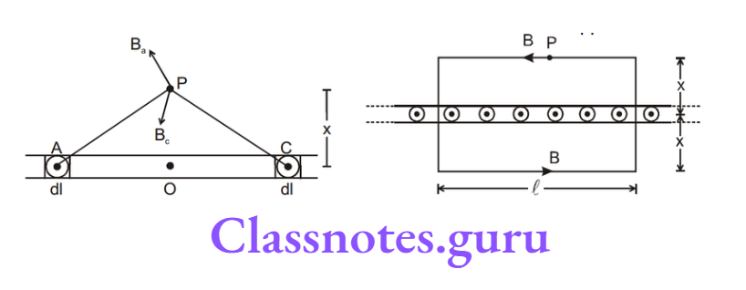
5. Fixed Loop In A Time-Varying Magnetic Field

Now consider a circular loop, at rest in a varying magnetic field. Suppose the magnetic field is directed inside the page and it is increasing in magnitude.

The emf induced in the loop will be \(\varepsilon=-\frac{d \phi}{d t}.\)

Flux through the coil will be \(\phi=-\pi r^2 B ; \frac{d \phi}{d t}=-\pi r^2 \frac{d B}{d t} ; \varepsilon=-\frac{d \phi}{d t}\)

∴ \(\varepsilon=\pi r^2 \frac{d B}{d t} . \)

∴ \(E 2 \pi r=\pi r^2 \frac{d B}{d t} \quad \text { or } \quad E=\frac{r}{2} \frac{d B}{d t}\)

Thus changing the magnetic field produces an electric field which is non-conservative in nature. Work done in the closed path on unit +ve charge is not zero. The lines of force associated with this electric field are closed curves.

6. Self Induction

Self-induction is the induction of emf in a coil due to its own current change. Total flux NΦ passing through a coil due to its own current is proportional to the current and is given as NΦ = L i where L is called the coefficient of self-induction or inductance.

The inductance L is purely a geometrical property i.e., we can tell the inductance value even if a coil is not connected in a circuit. Inductance depends on the shape and size of the loop and the number of turns it has.

If current in the coil changes by ΔI in a time interval At, the average emf induced in the coil is given as \(\varepsilon=-\frac{\Delta(\mathrm{N} \phi)}{\Delta \mathrm{t}}=-\frac{\Delta(\mathrm{LI})}{\Delta \mathrm{t}}=-\frac{\mathrm{L} \Delta \mathrm{I}}{\Delta \mathrm{t}}.\)

The instantaneous emf is given as \(\varepsilon=-\frac{\mathrm{d}(\mathrm{N} \phi)}{\mathrm{dt}}=-\frac{\mathrm{d}(\mathrm{LI})}{\mathrm{dt}}=-\frac{\mathrm{LdI}}{\mathrm{dt}}\)

S.I Unit of inductance is wb/amp or Henry(H)

L – self-inductance is +ve quantity.

L Depends On:

  1. Geometry of loop
  2. Medium in which it is kept. L does not depend upon the current.

L is a scalar quantity.

NEET Physics Class 12 Chapter 6: Electromagnetic Induction Formulas

6.1 Self-Inductance Of Solenoid

Let the volume of the solenoid be V, and the number of turns per unit length be n.

NEET Physics Class 12 Chapter 6 Electromagnetic Induction Self Inductance Of Solenoid

Let a current I be flow in the solenoid. The magnetic field in the solenoid is given as B = \(\mu_0 n l\). The magnetic flux through one turn of solenoid \(\phi=\mu_0 n \text { I A. }\)

The total magnetic flux through the solenoid = \(N \phi=N \mu_0 n I A=\mu_0 n^2 \mid A I\)

∴ L = \(\mu_0 \mathrm{n}^2 I A=\mu_0 n^2 V\)

Φ = \(\mu_0 n i \pi r^2(n \ell)\)

L = \(\frac{\phi}{\mathrm{i}}=\mu_0 \mathrm{n}^2 \pi \mathrm{r}^2 \ell\).

Inductance per unit volume = \(\mu_0 \mathrm{n}^2\).

Self-inductance is the physical property of the loop due to which it opposes the change in current which means it tries to keep the current constant. The current can not change suddenly in the inductor.

7. Inductor

It is represented  NEET Physics Class 12 Chapter 6 Electromagnetic Induction Inductor  by the electrical equivalence of a loop.

NEET Physics Class 12 Chapter 6 Electromagnetic Induction Inductor Electrical Equivalence Of Loop

If current i through the inductor is increasing the induced emf will oppose the increase in current and hence will be opposite to the current.

If current i through the inductor is decreasing the induced emf will oppose the decrease in current and hence will be in the direction of the current.

NEET Physics Class 12 Chapter 6 Electromagnetic Induction Current Through The Inductor Is Increasing The Induced EMF Will Opposite The Increase In Current

Note: If there is a resistance in the inductor (resistance of the coil of the inductor) then:

NEET Physics Class 12 Chapter 6 Electromagnetic Induction Resistance In The Inductor

Example: A B is a part of the circuit. Find the potential difference vA – vB if

NEET Physics Class 12 Chapter 6 Electromagnetic Induction AB Is A Part Of Circuit

  1. current i = 2A and is constant
  2. current i = 2A and is increasing at the rate of 1 amp/sec.
  3. current i = 2A and is decreasing at the rate of 1 amp/sec

NEET Physics Class 12 Chapter 6 Electromagnetic Induction Part Of Circuit Potential Difference

Solution:

L \(\frac{\mathrm{di}}{\mathrm{dt}}=1 \frac{\mathrm{di}}{\mathrm{dt}}\)

writing KVL from A to B \(V_A-1 \frac{d i}{d t}-5-2 i=V_B \text {. }\)

(1)Put \(i=2, \frac{d i}{d t}=0\); \(V_A-5-4=V_B\)

∴ \(V_A-V_B=9 \text { volt }\)

(2) Put \(\mathrm{i}=2, \frac{\mathrm{di}}{\mathrm{dt}}=1 ; \mathrm{V}_{\mathrm{A}}-1-5-4=\mathrm{V}_{\mathrm{B}}\) or \(\mathrm{V}_{\mathrm{A}}-\mathrm{V}_{\mathrm{B}}=10\) Volt

(3) Put \(\mathrm{i}=2, \frac{\mathrm{di}}{\mathrm{dt}}=-1 ; \mathrm{V}_{\mathrm{A}}+1-5-2 \times 2=\mathrm{V}_{\mathrm{B}}\) or \(\mathrm{V}_{\mathrm{A}}-\mathrm{V}_{\mathrm{B}}=8\) volt.

7.1 Energy Stored In An Inductor

If the current in an inductor at an instant is i and is increasing at the rate di/dt, the induced emf will oppose the current. Its behaviour is shown in the figure.

NEET Physics Class 12 Chapter 6 Electromagnetic Induction Energy Stored In An Inductor

Power consumed by the inductor = i L \(\frac{di}{dt}\)

Energy consumed in dt time = i L \(\frac{di}{dt}\) dt

∴ total energy consumed as the current increases from 0 to I = \(\int_0^1 \mathrm{iLdi}=\frac{1}{2} \mathrm{LI}^2\)

= \(\frac{1}{2} \mathrm{Li}^2 \quad \Rightarrow \quad \mathrm{U}=\frac{1}{2} \mathrm{LI}^2\)

This energy is stored in the magnetic field with energy density \(\frac{d U}{d V}=\frac{B^2}{2 \mu}=\frac{B^2}{2 \mu_0 \mu_r} \quad \text { Total energy } U=\int \frac{B^2}{2 \mu_0 \mu_r} d V\)

Example 2. A circuit contains an ideal cell and an inductor with a switch. Initially, the switch is open. It is closed at t=0. Find the current as a function of time.

NEET Physics Class 12 Chapter 6 Electromagnetic Induction A Circuit Contains An Ideal Cell And An Inductor With A Switch

Solution:

ε = \(\mathrm{L} \frac{\mathrm{di}}{\mathrm{dt}} \quad \Rightarrow \int_0^{\mathrm{i}} \varepsilon \mathrm{dt}=\int_0^{\mathrm{i}} \mathrm{Ldi} \Rightarrow \quad \varepsilon \mathrm{t}=\mathrm{Li} \Rightarrow \mathrm{i}=\frac{\varepsilon \mathrm{t}}{\mathrm{L}}\)

Example 3. In the following circuit, the switch is closed at t = 0. Find the currents \(\mathrm{i}_1, \mathrm{i}_2, \mathrm{i}_3 \text { and } \frac{\mathrm{di}_3}{\mathrm{dt}} \text { at } \mathrm{t}=0\). Initially, all currents are zero.

NEET Physics Class 12 Chapter 6 Electromagnetic Induction Current Cannot Suddenly Change Due To Inductor

Solution:

At t = 0

i3 is zero since the current cannot suddenly change due to the inductor.

∴ i1 = i2(from KCL)

applyingKVL in the part ABEF we get \(i_1=\frac{\varepsilon}{2 R} i_2=, i_3=0, \frac{d i_3}{d t}=\frac{\epsilon}{2 L}\)

At t = ∞

i3 will become constant and hence potential difference across the inductor will be zero. It is just like a simple wire and the circuit can be solved assuming it to be like shown in the following diagram.NEET Physics Class 12 Chapter 6 Electromagnetic Induction Potential Difference Across The Inductor Will be Zero

⇒ \(\mathrm{i}_2=\mathrm{i}_3=\frac{\varepsilon}{3 \mathrm{R}}, \mathrm{i}_1=\frac{2 \varepsilon}{3 \mathrm{R}}, \frac{d \mathrm{i}_3}{\mathrm{dt}}=0\)

7.2 Growth Of Current In Series R–L Circuit

Figure shows a circuit consisting of a cell, an inductor L and a resistor R, connected in series.

Let the switch S be closed at t=0. Suppose at an instant current in the circuit is i which is increasing at the rate di/dt.

NEET Physics Class 12 Chapter 6 Electromagnetic Induction Growth Of Current In Seried RL Circuit

Writing KVL along the circuit, we have \(\varepsilon-L \frac{d i}{d t}-\mathrm{i} R=0\)

On solving we get, \(\mathrm{i}=\frac{\varepsilon}{\mathrm{R}}\left(1-\mathrm{e}^{\frac{-\mathrm{Rt}}{\mathrm{L}}}\right)\)

The quantity L/R is called the time constant of the circuit and is denoted by τ. The variation of current with time is as shown.

NEET Physics Class 12 Chapter 6 Electromagnetic Induction Growth Of Current In Seried R-L Circuit

Note: 1. Final current in the circuit = \(\frac{\varepsilon}{\mathrm{R}}\), which is independent of L.

2. After one time constant, current in the circuit =63% of the final current (verify yourself)

3. More time constant in the circuit implies a slower rate of change of current.

4. If there is any change in the circuit containing the inductor then there is no instantaneous effect on the flux of the inductor.  L1i1 = L2i2

Example. At t = 0 switch is closed (shown in figure) after a long time suddenly the inductance of the inductor is made η times lesser \(\left(\frac{L}{\eta}\right)\) by pulling out the iron rod inserted in it then its initial value, find out instant current just after the operation.

NEET Physics Class 12 Chapter 6 Electromagnetic Induction Indtant Current just After The Operation

Solution:

Using above result \(L_1 i_1=L_2 i_2 \quad \Rightarrow \quad \mathrm{i}_2=\frac{\eta \varepsilon}{R}\)

7.3 Decay Of Current In The Circuit Containing Resistor And Inductor

Let the initial current in the circuit be I0. At any time t, let the current be i and let its rate of change at this instant be \(\frac{d i}{d t}\)

L\(\cdot \frac{\mathrm{di}}{\mathrm{dt}}+\mathrm{iR}=0\)

NEET Physics Class 12 Chapter 6 Electromagnetic Induction Decay Of Current In The Circuit Containg Resistor And Inductor

⇒ \(\frac{\mathrm{di}}{\mathrm{dt}}=-\frac{\mathrm{iR}}{\mathrm{L}}\)

⇒ \(\int_{i_0}^1 \frac{d i}{i}=-\int_0^t \frac{R}{L} \cdot d t \quad \Rightarrow \quad \ln \left(\frac{i}{I_0}\right)=-\frac{R t}{L} \text { or } i=I_0 e^{\frac{-R t}{L}}\)

Current after one-time constant: i = I0e-1 = 0.37% of initial current.

Equivalent Self Inductance: \(\mathrm{L}=\frac{\mathrm{V}_{\mathrm{A}}-\mathrm{V}_{\mathrm{B}}}{\mathrm{di} / \mathrm{dt}}\)…..(1)

NEET Physics Class 12 Chapter 6 Electromagnetic Induction Equivalent Self Inductance

Series Combination: \(V_A-L_1 \frac{d i}{d t}-L_2 \frac{d i}{d t}=V_B\) ….(2) from (1) and (2)

NEET Physics Class 12 Chapter 6 Electromagnetic Induction Parallel Combination Of Inductance

L = \(\mathrm{L}_1+\mathrm{L}_2\) (neglecting mutual inductance)

Parallel Combination:

From figure \(\mathrm{V}_{\mathrm{A}}-\mathrm{V}_{\mathrm{B}}=\mathrm{L}_1 \frac{\mathrm{di}_1}{\mathrm{dt}}=\mathrm{L}_2 \frac{\mathrm{di}_2}{\mathrm{dt}}\) also i = \(\mathrm{i}_1+\mathrm{i}_{\mathrm{z}}\)

NEET Physics Class 12 Chapter 6 Electromagnetic Induction Parallel Combination Of Self Inductance

or, \(\frac{d i}{d t}=\frac{d i_1}{d t}+\frac{d i_2}{d t}\) or \(\frac{V_A-V_B}{L}=\frac{V_A-V_B}{L_1}+\frac{V_A-V_B}{L_2}\)

∴ \(\frac{1}{L}=\frac{1}{L_1}+\frac{1}{L_2}\) (neglecting mutual inductance)

Example: An inductor having self-inductance L with its coil resistance R is connected across a battery of emfε. When the circuit is in a steady state at t = 0 an iron rod is inserted into the inductor due to which its inductance becomes n L (n> 1).

NEET Physics Class 12 Chapter 6 Electromagnetic Induction An Inductor Having Self Inductance

1. After insertion of the rod which of the following quantities will change with time?

  1. The potential difference across terminals A and B.
  2. Inductance.
  3. The rate of heat produced in the coil
  1. Only (1)
  2. (1) and (3)
  3. Only (3)
  4. (1), (2) and (3)

Solution:

Inductance and potential differences across terminals will not change with time.

2. After insertion of the rod, current in the circuit:

  1. Increases with time
  2. Decreases with time
  3. Remains constant with time
  4. First decreases with time then becomes constant

Solution:

Even after the insertion of the rod, the current in the circuit will increase with time till a steady state is reached.

Electromagnetic Induction Concept Notes for NEET Physics Class 12

3. When again circuit is in a steady state, the current in it is:

  1. \(K \varepsilon / R\)
  2. \(\mid>E / R\)
  3. \( I=\varepsilon / R\)
  4. None of these

Solution:

At steady state inductor will offer zero resistance and hence I = \(\varepsilon / R\).

8. Mutual Inductance

Consider two arbitrary conducting loops 1 and 2. Suppose that I1 is the instantaneous current flowing around loop 1. This current generates a magnetic field B1 which links the second circuit, giving rise to a magnetic flux Φ2 through that circuit.

NEET Physics Class 12 Chapter 6 Electromagnetic Induction Mutual Inductance

If the current I1 doubles, then the magnetic field B1 doubles in strength at all points in space, so the magnetic flux Φ2 through the second circuit also doubles.

Furthermore, it is obvious that the flux through the second circuit is zero whenever the current flowing around the first circuit is zero. It follows that the flux Φ2 through the second circuit is directly proportional to the current I1 flowing around the first circuit.

Hence, we can write Φ2 =M21 I1 where the constant of proportionality M21 is called the mutual inductance of circuit 2 with respect to circuit 1.

Similarly, the flux Φ2 through the first circuit due to the instantaneous current I2 flowing around the second circuit is directly proportional to that current, so we can write Φ1 =M12I2 where M12 is the mutual inductance of circuit 1 with respect to circuit 2.

It can be shown that M21= M12 (Reciprocity Theorem). Note that M is a purely geometric quantity, depending only on the size, number of turns, relative position, and relative orientation of the two circuits. The S.I. unit of mutual inductance is called Henry (H).

One Henry is equivalent to a volt-second per ampere:

Suppose that the current flowing around circuit 1 changes by an amount ΔI1 in a small time interval Δt.

The flux linking circuit 2 changes by an amount ΔΦ2=MΔI1 in the same time interval.

According to Faraday’s law, an emf \(\varepsilon_2=-\frac{\Delta \phi_2}{\Delta \mathrm{t}}\) is generated around the second circuit due to the changing magnetic flux linking that circuit.

Since, \(\Delta \phi_2=M \Delta \mathrm{I}_1\), this emf can also be written \(\varepsilon_2=-M \frac{\Delta \mathrm{l}_1}{\Delta \mathrm{t}}\)

Thus, the emf generated around the second circuit due to the current flowing around the first circuit is directly proportional to the rate at which that current changes.

Likewise, if the current I2 flowing around the second circuit changes by an amount ΔI1 in a time interval Δt then the emf generated around the first circuit is \(\varepsilon_1=-M \frac{\Delta l_2}{\Delta t}\)

Note that there is no direct physical connection(coupling) between the two circuits: the coupling is due entirely to the magnetic field generated by the currents flowing around the circuits.

Note:

  1. \(M \leq \sqrt{L_1 L_2}\)
  2. For two coils in series if mutual inductance is considered then \(\mathrm{L}_{\mathrm{eq}}=\mathrm{L}_1+\mathrm{L}_2 \pm 2 \mathrm{M}\)

Unit Of \(\mathbf{M}\): In M.K.S. system unit of mutual inductance is henry

M = \(\frac{E_B}{-\left(\mathrm{dI}_{\mathrm{A}} / \mathrm{dT}\right)}=\frac{\phi_B}{I_A}\)

∴ 1 henry = \(\frac{1 \text { volt }}{1 \text { ampere } / \mathrm{s}}=\frac{1 \text { weber }}{\text { ampere }}=\frac{\text { (joule } / \text { coulomb)s }}{\text { ampere }}=\mathrm{J} / \mathrm{A}^2\)

Dimensions Of M:

M = \(\frac{J}{A^2}=\frac{\text { joule }}{\text { ampere }^2}=\frac{\text { newton } \times \text { metre }}{\text { ampere }^2}=\frac{\mathrm{kg} \times \text { metre } \times \mathrm{sec}^{-2} \times \text { metre }}{\text { ampere }^2}=\mathrm{ML}^2 \mathrm{~T}^{-2} \mathrm{~A}^{-2}\)

Mutual inductance between the coils depends upon the number of turns in the coils, the area and the permeability of the core placed inside the coils. The larger the magnitude of M, the more is the emf induced in the secondary coil.

Out of the two coils coupled magnetically one coil can be taken as primary and the other coil as secondary. Thus mutual inductance MAB = MBA = M

Mutual inductance between two coaxial solenoids of length l and cross-sectional area A is M = \(\frac{\mu_0 \mathrm{~N}_1 \mathrm{~N}_2 \mathrm{~A}}{\ell}\) = where N1 and N2 are the number of turns in the two coils respectively.

If two coils are wound one over the other, then mutual inductance will be maximum and it will be less in other arrangements.

M and L have the following relation: \(M \propto \sqrt{L_1 L_2}\)

NEET Physics Class 12 Chapter 6 Electromagnetic Induction If Two Coils Are Wound One Over The Other Then Mutual Inductance

M = \(K \sqrt{L_1 L_2}\)

where K is a coupling constant of coils and its value varies from 0 to 1.

  1. If K = 0, then there will be no coupling between the coils, that is magnetic flux produced by the primary coil is not linked with the secondary coil.
  2. If K = 1, then both coils are coupled together with maximum transfer to energy, that is, the magnetic flux produced by the primary coil is totally linked with the secondary coil.

If two coils of self inductances L1 and L2 are coupled in series such that their windings are in the same sense and the mutual inductance between them is M, then the equivalent inductance will be L = L1 + L2 + 2M

NEET Physics Class 12 Chapter 6 Electromagnetic Induction Two Coils Of Self Inductance Are Coupled Series

If two coils are coupled in series such that their windings are in opposite sense then equivalent inductance will be L = L1 + L2 – 2M

NEET Physics Class 12 Chapter 6 Electromagnetic Induction If Two Coils Are Coupled In Series

Electromagnetic Induction Concept Notes for NEET Physics Class 12

8. Mutual Inductance Solved Examples

Example 1. A coil of radius 1 cm and 100 turns is placed at the centre of a long solenoid of radius 5 cm and 8 turns/cm. The value of the coefficient of mutual induction will be

  1. 3.15 × 10⁻⁵ H
  2. 6 × 10⁻⁵ H
  3. 9 × 10⁻⁵ H
  4. Zero

Solution:

M = \(\mu_0 n_1 N_2 \pi \pi^2=4 \pi \times 10^{-7} \times 800 \times 100 \pi \times(0.01)^2=3.15 \times 10^{-5} \mathrm{H}\)

Hence the correct answer will be (1)

Example 2. The coefficients of self induction of two coils are 0.01 H and 0.03 H respectively. If they oppose each other then the resultant self-induction will be, if M = 0.01H

  1. 2H
  2. 0.02H
  3. 0.02H
  4. Zero

Solution:

L = L1 + L2 – 2M = 0.01 + 0.03 – 2 × 0.01

Hence the correct answer will be (3)

Example 3. Two insulated wires are wound on the same hollow cylinder, so as to form two solenoids sharing a common air-filled core. Let I be the length of the core, A the cross-sectional area of the core, N1 the number of times the first wire is wound around the core, and N2 the number of turns the second wire is wound around the core. Find the mutual inductance of the two solenoids,neglecting the end effects.

Solution:

If a current I1 flows around the first wire then a uniform axial magnetic field of strength \(B_1=\frac{\mu_0 N_1 l_1}{\ell}\) is generated in the core. The magnetic field in the region outside the core is of negligible magnitude. The flux linking a single turn of the second wire is B1A.

Thus, the flux linking all N2 turns of the second wire is \(\phi_2=\mathrm{N}_2 \mathrm{~B}_1 \mathrm{~A}=\frac{\mu_0 \mathrm{~N}_1 \mathrm{~N}_2 \mathrm{Al}_1}{\ell}=\mathrm{MI}_1\)

∴ M = \(\frac{\mu_0 N_1 N_2 \mathrm{~A}}{\ell}\)

As described previously, M is a geometric quantity depending on the dimensions of the core and the manner in which the two wires are wound around the core, but not on the actual currents flowing through the wires.

Example 4. Find the mutual inductance of two concentric coils of radii a1 and a2 (a1<< a2) if the planes of coils are the same.

NEET Physics Class 12 Chapter 6 Electromagnetic Induction Mutula Inductance Of Two Concentric Coils

Solution:

Let a current i flow in a coil of radius a2

Magnetic field at the centre of coil = \(\frac{\mu_0 \mathrm{i}}{2 \mathrm{a}_2} \pi \mathrm{a}_1^2\)

or \(M i=\frac{\mu_0 i}{2 a_2} \pi a_1{ }^2\) or \(M=\frac{\mu_0 \pi a_1^2}{2 a_2}\)

Example 5. Solve the above question, if the planes of coil are perpendicular.

Solution:

Let a current i flow in the coil of radius a1. The magnetic field at the centre of this coil will now be parallel to the plane of smaller coil and hence no flux will pass through it, M = 0.

Example 6. Solve the above problem if the planes of coils make θ angles with each other.

Solution:

If I current flows in the larger coil, magnetic field produced at the centre will be perpendicular to the plane of larger coil.

Now the area vector of smaller coil which is perpendicular to the plane of smaller coil will make an angle θ with the magnetic field.

Thus flux = \(\vec{B} \cdot \vec{A}=\frac{\mu_0 \mathrm{i}}{2 \mathrm{a}_2} \cdot \pi \mathrm{a}_1^2 \cdot \cos \theta\) or \(\mathrm{M}=\frac{\mu_0 \pi \mathrm{a}_1^2 \cos \theta_1}{2 \mathrm{a}_2}\)

Example 7. The figure shows two concentric coplanar coils with radii a and b (a << b). A current i = 2t flows in the smaller loop. Neglecting self-inductance of the larger loop

NEET Physics Class 12 Chapter 6 Electromagnetic Induction Two Concentric Coplanar Coils

  1. Find the mutual inductance of the two coils
  2. Find the emf induced in the larger coil
  3. If the resistance of the larger loop is R find the current in it as a function of time

Solution:

(1) To find mutual inductance, it does not matter in which coil we consider current and in which flux is calculated (Reciprocity theorem) Let current I be flowing in the larger coil. Magnetic field at the centre = \(\frac{\mu_0 \mathrm{i}}{2 \mathrm{~b}}\)

flux through the smaller coil = \(\frac{\mu_0 i}{2 b} \pi a^2\)

∴ M = \(\frac{\mu_0}{2 b} \pi a^2\)

(2) |emf induced in larger coil| = M \(\mathrm{M}\left[\left(\frac{\mathrm{di}}{\mathrm{dt}}\right) \text { in smaller coil }\right](2)=\frac{\mu_0 \pi \mathrm{a}^2}{\mathrm{~b}}\)

(3) current in the larger coil = \(\frac{\mu_0 \pi \mathrm{a}^2}{\mathrm{bR}}\)

9. Eddy Current

When a conductor is placed in a changing magnetic field, induced EMF is produced in it. As a result local currents are produced in the conductor. These local currents are called eddy currents.

  • If a conducting material is moved in a magnetic field, then eddy currents are also produced.
  • Eddy currents flows in closed paths.
  • There is a loss of energy due to eddy currents and it appears in the form of heat.
  • In order to minimize the energy loss in the form of heat due to eddy currents the core of dynamo, motor or transformer is not taken as a single piece of soft iron but in the form of a peck of thin sheets insulated from each other by a layer of insulating varnish, called laminated core.
  • This device increases the resistance for the eddy currents. In this way eddy currents are considerably reduced and loss of energy becomes less.

NEET Physics Class 12 Chapter 6 Electromagnetic Induction Eddy Currents

Uses Of Eddy Currents:

  1. Moving coil galvanometer
  2. Induction furnace
  3. Dead beat galvanometer
  4. Speedometer
  5. Electric brakes

10. Generator Or Dynamo

A generator or dynamo is an electrical device which converts mechanical energy into electrical energy.

The working of generators is based on the principle of electromagnetic induction.

Generators Are Of Two Types:

  1. A.C. Generator: If the current produced by the generator is alternating, then the generator is called A.C. generator.
  2. D.C. Generator: If the current produced by the generator is direct current, then the generator is called a D.C. generator.

NEET Physics Class 12 Chapter 6 Electromagnetic Induction Generator Or Dynamo

Generator consists of the following parts.

  1. Armature (coil)
  2. Magnet
  3. Slip rings
  4. Brushes

In D.C. generator commutator is used in place of slip rings.

In order to produce the magnetic field in big generators several magnetic poles are used. In these generators the armature coils are kept stationary and magnetic pole pieces are made to rotate around the armature.

The frequency of alternating current produced by generator of multi poles is = \(\frac{\text { number of poles } \times \text { rotational frequency }}{2}=\frac{\mathrm{Nn}}{2}\)

Energy Loss In Generators: The loss of energy is due to the following reasons

  1. Flux leakage,
  2. Copper losses,
  3. Eddy’s current losses,
  4. Hysteresis losses,
  5. Mechanical losses

Efficiency Of Generator: Practical efficiency of a generator = \(\frac{\text { Electrical power generated by the generator }}{\text { Mechanical energy given to the generator }}\)

Practical efficiencies of big generators are about 92% to 95%.

11. Motor

It converts electrical energy into mechanical energy.

When a current carrying conductor (coil) is placed in a magnetic field, a couple acts on it which makes the coil to rotate.

Electric Motors Are Of Two Types:

  1. Alternating current motor (AC motor)
  2. Direct current motor (DC motor)

D.C. Motor Consists Of The Following Parts:

  1. Armature
  2. Magnet
  3. Commentator
  4. Brushes

Back E.M.F: When current from an external electric source is passed through the armature of the electric motor, the armature coil rotates in the magnetic field.

It cuts the magnetic lines of force as a result EMF is induced in it. According to Lenz’s law this induced emf opposes the rotation of the armature i.e., the emf induced works opposite to the emf applied by the external electric source and opposes the motion of the armature.

This induced emf is called back emf. The greater the speed of the armature coil, the greater is the back emf.

At the time of start of the motor back emf is almost zero and the current flowing in the motor is maximum. As the speed of the armature coil increases, back emf also increases.

When the coil increases, back emf also increases. When the coil attains maximum speed, the induced emf becomes constant and current reduced to minimum.

Back emf is directly proportional to the angular velocity ω of rotation of armature and the magnetic field B, i.e., for constant magnetic field back emf. e ∝ ω or e = Kω where K is a constant.

If E is applied emf, e is the back emf and R is the resistance of the coil (armature), then the current flowing through the coil will be

i = \(\frac{E-e}{R} \quad \text { or } \quad E=e+i R \quad \text { but } \quad e=K \omega\)

∴ \(i=\frac{E-K \omega}{R}\)

In the beginning, i.e. at the time of the start of the motor ω = 0

∴ i = \(\frac{E}{R}\)

In this case current will be maximum.

  • As the armature coil is made from copper wire its resistance is very small. When the motor starts running, a very heavy current passes through the armature coil in the beginning.
  • Due to which motor may get burnt.
  • To prevent the motor from burning at the time of start a special variable resistance is connected in series with the armature, which is called starter.
  • High resistance is connected in series with the armature coil with the help of starter at the time of start of the motor.
  • As the motor starts picking up speed, the resistance is gradually reduced till it becomes zero.
  • The starter is used in a high power motors but not in the low power motors because its coil starts rotating at a very high speed in a short time

Power of electric motor = ie

Efficiency of motor

η = \(\frac{\text { Work done by the motor }}{\text { Energy taken from the electric source by the motor }}=\frac{W}{P} \times 100 \%\)

or \(\eta =\frac{\text { Back emf }}{\text { Applied emf }} \times 100 \%=\frac{e}{E} \times 100 \%\)

Generally, the efficiency of the motor is from 80% to 90%.

11. Motor Solved Miscellaneous Problems

Problem 1. Find the emf across the points P and Q which are diametrically opposite points of a semicircular closed loop moving in a magnetic field as shown. Also, draw the electrical equivalent circuit of each branch.

NEET Physics Class 12 Chapter 6 Electromagnetic Induction EMF Across The Points With Are Diametrically Opposite Points Of Semicircular Closed Loop Moving Magnetic Field

Solution:

here \(\overrightarrow{\mathrm{v}} \| \vec{\ell}\)

So,emf = \(\vec{\ell} \cdot(\overrightarrow{\mathrm{v}} \times \overrightarrow{\mathrm{B}})=0\)

Induced emf = 0

NEET Physics Class 12 Chapter 6 Electromagnetic Induction Electrical Equivalent Circuit Of Each Branch

Problem 2. Find the emf across the points P and Q which are diametrically opposite points of a semicircular closed loop moving in a magnetic field as shown. Also, draw the electrical equivalence of each branch.

NEET Physics Class 12 Chapter 6 Electromagnetic Induction EMF Across The Points which Are Diametrically Opposite Points Of A Semicicular Closed loop Moving Magnetic Field

Solution:

Induced emf = 2Bav

NEET Physics Class 12 Chapter 6 Electromagnetic Induction EMF Across The Points which Are Diametrically Opposite Points Of A Electrical Equivalence Of Each Branch

Problem 3. Figure shows a rectangular loop moving in a uniform magnetic field. Show the electrical equivalence of each branch.

NEET Physics Class 12 Chapter 6 Electromagnetic Induction Rectangular Loop Moving In A Uniform Magnetic Field

Solution:

NEET Physics Class 12 Chapter 6 Electromagnetic Induction Rectangular Loop Moving Electrical Equivalence

Problem 4. The figure shows a rod of length l and resistance r moving on two rails shorted by a resistance R. A uniform magnetic field B is present normal to the plane of rod and rails. Show the electrical equivalence of each branch.

NEET Physics Class 12 Chapter 6 Electromagnetic Induction Rod Of Length And Resistance Moving On Two Rails

Solution:

NEET Physics Class 12 Chapter 6 Electromagnetic Induction Fixed Conducting Thick Rails

Class 12 Physics Electromagnetic Induction Notes for NEET

Problem 5. A rod PQ of length 2l is rotating about its midpoint C, in a uniform magnetic field B which is perpendicular to the plane of rotation of the rod. Find the induced emf between PQ and PC. Draw the circuit diagram of parts PC and CQ.

NEET Physics Class 12 Chapter 6 Electromagnetic Induction Circuit Diagram

Solution:

∴ \(\mathrm{emf}_{\mathrm{PQ}}=0 ; \mathrm{emf}_{\mathrm{PC}}=\frac{\mathrm{B} \omega \ell^2}{2}\)

Problem 6. Which of the two curves shown has less time constant?

NEET Physics Class 12 Chapter 6 Electromagnetic Induction Two Curves Shown Has less Time Constant

Solution:

curve 1

Problem 7. Find the mutual inductance of a straight long wire and a rectangular loop, as shown in the figure

NEET Physics Class 12 Chapter 6 Electromagnetic Induction Mutual Inductance Of A Straight Long Wore And A Rectangular loop

Solution:

⇒ \(d \phi=\frac{\mu_0 i}{2 \pi r} \times b d r\)

NEET Physics Class 12 Chapter 6 Electromagnetic Induction Mutual Inductance Of A Straight Long Wire

⇒ \(\phi=\int_x^{x+a} \frac{\mu_0 i}{2 \pi r} \times b d r \quad \Rightarrow \quad M=\phi / l \quad \Rightarrow \quad M=\frac{\mu_0 b}{2 \pi} \ln \left(1+\frac{a}{x}\right)\)

Chapter 6 Electromagnetic Induction Key Concept

Magnetic flux is mathematically defined as \(\phi=\int \overrightarrow{\mathrm{B}} \cdot \mathrm{d} \overrightarrow{\mathrm{s}}\)

Faraday’s Laws Of Electromagnetic Induction

When magnetic flux passing through a loop changes with time or magnetic lines of force are cut by a conducting wire then an emf is produced in the loop or in that wire.

The magnitude of induced emf is equal to the rate of change of flux w.r.t. time in the case of a loop. In the case of a wire, it is equal to the rate at which magnetic lines of force are cut by a wire.

∴ \(\epsilon=-\frac{d \phi}{d t}\)

A negative sign implies that emf induces in such a way opposition to change in flux.

Lenz’s Law(based on the conservation of energy principle)

According to this law, emf will be induced in such a way that it will oppose the cause which has produced it.

If a wire AB is moving with constant velocity \(\vec{v}\) in a uniform magnetic field \(\vec{B}\) then emf induced in any path joining A and B is same which is equal to \((\overrightarrow{\mathrm{AB}}) \cdot(\overrightarrow{\mathrm{V}} \times \overrightarrow{\mathrm{B}})\) where L is the distance between A and B.

Induced Emf Due To Rotation Of Ring: Emf induced in a conducting rod of length l rotating with angular speed ra about its one end, in a uniform magnetic field B perpendicular to the plane of rotation is 1/2 B ωl².

EMF Induced In A Rotating Disc: Emf between the centre and the edge of the disc of radius r rotating in a magnetic field \(\mathrm{B}=\frac{\mathrm{B} \omega \mathrm{r}^2}{2}\)

NEET Physics Class 12 Chapter 6 Electromagnetic Induction EMF Induced In Rotating Disc

Self-Induction: Self-induction is the induction of emf in a coil due to its own current change. Total flux NΦ passing through a coil due to its own current is proportional to the current and is given as NΦ= L i where L is called the coefficient of self-induction or inductance.

The inductance L is purely a geometrical property.

If the current in the coil changes by ΔI in a time interval Δt, the average emf induced in the coil is given as \(\varepsilon=-\frac{\Delta(\mathrm{N} \phi)}{\Delta \mathrm{t}}=-\frac{\Delta(\mathrm{LI})}{\Delta \mathrm{t}}=-\frac{\mathrm{L} \Delta \mathrm{I}}{\Delta \mathrm{t}}\)

The instantaneous emf is gien as \(\varepsilon=-\frac{\mathrm{d}(\mathrm{N} \phi)}{\mathrm{dt}}=-\frac{\mathrm{d}(\mathrm{LI})}{\mathrm{dt}}=-\frac{\mathrm{Ldl}}{\mathrm{dt}}\)

Self inductance of solenoid = \(\mu_0 \mathrm{n}^2 \pi \mathrm{r}^2 \ell\)

Inductor: It is represented  NEET Physics Class 12 Chapter 6 Electromagnetic Induction Inductor by the electrical equivalence of the loop

NEET Physics Class 12 Chapter 6 Electromagnetic Induction Energy Stored In Inductor

Energy stored in an inductor = \(\frac{1}{2}\) LI²

Growth Of Current in Series R-L Circuit:

If a circuit consists of a cell, an inductor L a resistor R and a switch S, connected in series and the switch is closed at t = 0, the current in the circuit I will increase as i = \(\frac{\varepsilon}{R}\left(1-e^{\frac{-R t}{L}}\right)\)

1. Final current in the circuit = \(\frac{\varepsilon}{\mathrm{R}}\), which is independent of L.

NEET Physics Class 12 Chapter 6 Electromagnetic Induction Growth Of Current In Seried R-L Circuit

2. After one time constant, the current in the circuit =63% of the final current.

Properties Of R-L Circuit

  1. At t = 0, the inductor behaves like an open circuit.
  2. At t = ∞ (after a very long time), the inductor behaves like a short-circuited wire.
  3. Currently in inductor has not abruptly changed.

Decay Of Current In The Circuit Containing Resistor And Inductor:

Let the initial current in a circuit containing an inductor and resistor be I0. Current at a time t is given as i = \(\mathrm{I}_0 e^{\frac{-\mathrm{Rt}}{\mathrm{L}}}\)

Mutual Inductance: This is the induction of EMF in a coil (secondary) due to a change in current in another coil (primary). If the current in the primary coil is i, the total flux in the secondary is proportional to i, i.e. N Φ (in secondary) ∝i.

or N Φ (in secondary) = M i.

Equivalent Self Inductance: L = \(\frac{V_A-V_B}{d i / d t}\)…..(1)

NEET Physics Class 12 Chapter 6 Electromagnetic Induction Equivalent Self Inductance

Series Combination:

L = L1 + L2 (neglecting mutual inductance)

L = L1 + L2 + 2M (if coils are mutually coupled and they have winding in the same direction)

L = L1 + L2 – 2M (if coils are mutually coupled and they have to wind in opposite directions)

Parallel Combination: \(\frac{1}{L}=\frac{1}{L_1}+\frac{1}{L_2}\) (neglecting mutual inductance)

For two coils which are mutually coupled, it has been found that \(M \sqrt{L_1 L_2} \text { or } M=k \sqrt{L_1 L_2}\) where k is called coupling constant and its value is less than or equal to 1.

L.C. Oscillations: Let a capacitor be charged to Q and then connected in series with an inductor with the help of a switch as shown in the figure.

NEET Physics Class 12 Chapter 6 Electromagnetic Induction L C Oscillator

Let the switch be closed at t=0. Let at a time t=t, the charge on the capacitor be q and the current in the circuit be i where i = – \(\frac{dq}{dt}\).

Writing Kirchoff’s equation,we get \(\frac{q}{C}=L \frac{d i}{d t}=-L \frac{d^2 q}{d t^2} \text { or } \frac{d^2 q}{d t^2}+\frac{q}{L C}=0 \text {. }\)

Compared with the standard differential equation it can be easily seen that therefore time period T = \(2 \pi \sqrt{L C}\).

Example: Figure shows a conducting rod of negligible resistance that can slide on a smooth U-shaped rail made of wire of resistance 1 Ω/m. The position of the conducting rod at t = 0 is shown. A time t-dependent magnetic field B = 2t Tesla is switched on at t = 0.

NEET Physics Class 12 Chapter 6 Electromagnetic Induction Conducting Rod Of negligible Resistance That Can Slide On Smooth U Shaped

1. The current in the loop at t = 0 due to induced emf is

  1. 0.16 A, clockwise
  2. 0.08 A, clockwise
  3. 0.08 A, anticlockwise
  4. zero

Solution:

⇒ \(\frac{\mathrm{dB}}{\mathrm{dt}}=2 \mathrm{~T} / \mathrm{s} \quad \mathrm{E}=-\frac{\mathrm{AdB}}{\mathrm{dt}}=-800 \times 10^{-4} \mathrm{~m}^2 \times 2=-0.16 \mathrm{~V}, \quad \mathrm{i}=\frac{0.16}{1 \Omega}\)

= \(0.16 \mathrm{~A}, \text { clockwise }\).

2. At t = 0, when the magnetic field is switched on, the conducting rod is moved to the left at a constant speed of 5 cm/s by some external means. The rod moves remaining perpendicular to the rails. At t = 2s, induced emf has magnitude.

  1. 0.12 V
  2. 0.08 V
  3. 0.04 V
  4. 0.02 V

Solution:

At t = 2 \(\mathrm{~s} \quad \mathrm{~B}=4 \mathrm{~T} ; \frac{\mathrm{dB}}{\mathrm{dt}}=2 \mathrm{~T} / \mathrm{s}\)

A = \(20 \times 30 \mathrm{~cm}^2\)

= \(600 \times 10^{-4} \mathrm{~m}^2 ; \frac{d A}{d t}=-(5 \times 20) \mathrm{cm}^2 / \mathrm{s} \quad=-100 \times 10^{-4} \mathrm{~m}^2 / \mathrm{s}\)

E = \(-\frac{d \varphi}{d t}=-\left[\frac{d(B A)}{d t}\right]=-\left[\frac{B d A}{d t}+\frac{A d B}{d t}\right]\)

= \(-\left[4 \times\left(-100 \times 10^{-4}\right)+600 \times 10^{-4} \times 2\right]=-[-0.04+0.120]=-0.08 \mathrm{~V}\)

Alternative: \(\phi=B A=2 t \times 0.2(0.4-v t)\)

= \(0.16 \mathrm{t}-0.4 \mathrm{vt}^2\)

E = \(-\frac{d \phi}{d t}=0.8 \mathrm{vt}-0.16\) at \(\mathrm{t}=2 \mathrm{~s}\)

E = -0.08 V

3. Following the situation of the previous question, the magnitude of the force required to move the conducting rod at a constant speed of 5 cm/s at the same instant t = 2s, is equal to

  1. 0.16 N
  2. 0.12 N
  3. 0.08 N
  4. 0.06 N

Solution: At t = 2s, length of the wire= (2 × 30 cm) + 20 cm = 0.8 m

Resistance of the wire = 0.8

Current through the rod = \(\frac{0.08}{0.8}=\frac{1}{10} \mathrm{~A}\)

Force on the wire = I l B = \(\frac{1}{10}\) × (0.2) × 4 = 0.08 N

The same force is applied on the rod in the opposite direction to make net force zero.

Electromagnetic Induction NEET Physics Chapter 6 Summary

Problem: A rod PQ of length l is rotating about end P, with an angular velocity ω. Due to centrifugal forces, the free electrons in the rod move towards the end Q and an emf is created. Find the induced emf.

NEET Physics Class 12 Chapter 6 Electromagnetic Induction Rod PQ Of Length Is Rotating About End P With Angular Velocity

Solution:

The accumulation of free electrons will create an electric field which will finally balance the centrifugal forces and a steady state will be reached.

In the steady state meω²x = e E

∴ \(\left.V_p-V_Q=\int_{x=0}^{x=\ell} \bar{E} \cdot d \bar{x}=\int_0^{\ell} \frac{m_e \omega^2 x}{e} d x=\frac{m_e \omega^2 \ell^2}{2 e} \approx 10^{-12} V \quad \text { (If } \omega=1, \ell=1\right)\)

This value is very small.

Chapter 6 Electromagnetic Induction Questions And Answers

Question 1. A thin semicircular conducting ring of radius R is falling with its plane vertically in a horizontal magnetic induction B. At the position MNQ the speed of the ring is v then the potential difference developed across the ring is:

NEET Physics Class 12 Chapter 6 Electromagnetic Induction A Thin Se,icircular Conducting Ring Of Radius

  1. Zero
  2. \(\frac{B v \pi R^2}{2}\)
  3. π RBV and Q have a higher potential
  4. 2 RBV and Q are at higher potential.

Answer: 4. 2 RBV and Q are at higher potential.

Induced motional emf in MNQ is equivalent to the motional emf in an imaginary wire MQ i.e., eMNQ = eMQ = Bvl = Bv (2R)

[l = MQ = 2R]

Therefore, the potential difference developed across the ring is 2RBv with Q at a higher potential.

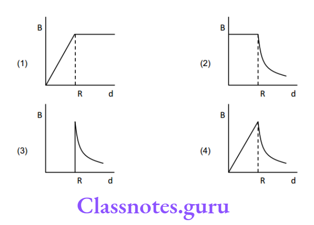
Question 2. A cylindrical space of radius R is filled with a uniform magnetic induction B parallel to the axis of the cylinder. If B changes at a constant rate, the graph showing the variation of the induced electric field with distance r from the axis of the cylinder is

NEET Physics Class 12 Chapter 6 Electromagnetic Induction A Cylindral Space Of Radius

Answer: 1

EMF = \(-\frac{\mathrm{d} \phi}{\mathrm{dt}}=-\frac{\mathrm{dB} \pi \mathrm{r}^2}{\mathrm{dt}}=-\pi \mathrm{r}^2 \frac{\mathrm{dB}}{\mathrm{dt}} \text { or } \mathrm{E}=\left(\frac{\mathrm{EMF}}{2 \pi \mathrm{r}}\right)=\left(\frac{\mathrm{dB}}{\mathrm{dt}}\right) \frac{\mathrm{r}}{2}
\)

or \(E \propto r\) for \(r \leq R\).

E \(\propto \frac{1}{r}\) for r>R.

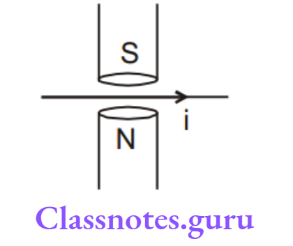
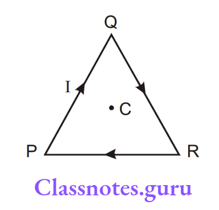
Question 3. In a cylindrical region uniform magnetic field which is perpendicular to the plane of the figure is increasing with time and a conducting rod PQ is placed in the region. If C is the centre of the circle then

NEET Physics Class 12 Chapter 6 Electromagnetic Induction In A Cylindrical Region Uniform Magnetic Field

  1. P will be at a higher potential than Q.
  2. Q will be at a higher potential than P.
  3. Both P and Q will be equipotential.
  4. No EMF will be developed across the rod as it is not crossing/cutting any line of force.

Answer: 2. Q will be at a higher potential than P.

If the circuit Q C P containing rod PQ is completed then the direction of induced current will be from Q to C to P hence Q will be at a higher potential than P.

Question 4. In a series L-R growth circuit, if the maximum current and maximum induced emf in an inductor of inductance 3mH are 2A and 6V respectively, then the time constant of the circuit is:

  1. 1 ms.
  2. 1/3 ms.
  3. 1/6 ms
  4. 1/2 ms

Answer: 1. 1 ms.

R = \(\frac{V}{I}\)

∴ \(\tau=\frac{L}{R}=1 \mathrm{~ms}\)

Question 5. Two coils of self-inductance 100 mH and 400 mH are placed very close to each other. Find the maximum mutual inductance between the two when 4 A current passes through them

  1. 200 mH
  2. 300 mH
  3. 100√2 mH
  4. None of these

Answer: 1. 200 mH

∴ \(M_{\max }=\sqrt{L_1 L_2}=\sqrt{100 \times 400} \mathrm{mH}=200 \mathrm{mH} \text {. }\)

Question 6. A nonconducting ring of radius R and mass m having charge q uniformly distributed over its circumference is placed on a rough horizontal surface. A vertical time-varying uniform magnetic field B = 4t² is switched on at time t=0. The coefficient of friction between the ring and the table, if the ring starts rotating at t =2 sec, is :

NEET Physics Class 12 Chapter 6 Electromagnetic Induction Non Conducting Ring Of Radius And Mass

  1. \(\frac{4 q m R}{g}\)
  2. \(\frac{2 q m R}{g}\)
  3. \(\frac{8 q R}{m g}\)
  4. \(\frac{q R}{2 m g}\)

Answer: 3. \(\frac{8 q R}{m g}\)

\(\int E d \ell=-\frac{d \phi}{d t}\)

E \(\times 2 \pi R=\pi R^2 \frac{d B}{d t}\)

E = \(\frac{R}{2} \times 8 t=R 8\)

(qE)R  = \((\mu \mathrm{mg}) R\)

μ \(=\frac{8 q R}{m g}\)

Question 7. In the figure shown a square loop PQRS of side ‘a’ and resistance ‘r’ is placed near an infinitely long wire carrying a constant current I. The sides PQ and RS are parallel to the wire. The wire and the loop are in the same plane. The loop is rotated by 180° about an axis parallel to the long wire and passes through the midpoints of the side QR and PS. The total amount of charge which passes through any point of the loop during rotation is:

NEET Physics Class 12 Chapter 6 Electromagnetic Induction Total amount Of Carge Which Passes Through Any Poit Of The loop

  1. \(\frac{\mu_0 \mathrm{Ia}}{2 \pi \mathrm{r}} \ell \mathrm{n} 2\)
  2. \(\frac{\mu_0 \text { Ia }}{\pi}\) en2
  3. \(\frac{\mu_0 I a^2}{2 \pi r}\)
  4. Cannot be found because the time of rotation is not given.

Answer: 2. \(\frac{\mu_0 \text { Ia }}{\pi}\) en2

q = \(\int \mathrm{Idt}=\int-\frac{1}{\mathrm{r}} \frac{\mathrm{d} \phi}{\mathrm{dt}} \mathrm{dt}=-\frac{\Delta \phi}{\mathrm{r}}=\frac{\mu_0 \mathrm{Ia}}{\pi \mathrm{r}} \ell \mathrm{n} 2\).

Question 8. Shows a conducting loop being pulled out of a magnetic field with a constant speed v. Which of the four plots shown in fig. may represent the power delivered by the pulling agent as a function of the constant speed v?

NEET Physics Class 12 Chapter 6 Electromagnetic Induction Conducting Loop Being Pulled Out Of A Magnetic Field

  1. A
  2. B
  3. C
  4. D

Answer: 2. B

P = \(\mathrm{F} . \mathrm{V}=\mathrm{Bi} \ell \mathrm{V}=\mathrm{B}\left(\frac{\mathrm{Bv} \ell}{\mathrm{R}}\right) \ell \mathrm{V}, \mathrm{P} \propto \mathrm{V}^2\)

Question 9. A uniform magnetic field, B = B0 t (where B0 is a positive constant), fills a cylindrical volume of radius R, then the potential difference in the conducting rod PQ due to the electrostatic field is:

NEET Physics Class 12 Chapter 6 Electromagnetic Induction A Uniform Magnetic Field

  1. \(\mathrm{B}_0 \ell \sqrt{\mathrm{R}^2+\ell^2}\)
  2. \(\mathrm{B}_0 \ell \sqrt{\mathrm{R}^2-\frac{\ell^2}{4}}\)
  3. \(\mathrm{B}_0 \ell \sqrt{\mathrm{R}^2-\ell^2}\)
  4. \(B_0 R \sqrt{R^2-\ell^2}\)

Answer: 3. \(\mathrm{B}_0 \ell \sqrt{\mathrm{R}^2-\ell^2}\)

∫\(\mathrm{Ed} \ell=\varepsilon, \mathrm{E}=\frac{\mathrm{r}}{2} \frac{\mathrm{dB}}{\mathrm{dt}}, \quad \mathrm{E} \cos \theta=\frac{\mathrm{r} \cos \theta}{2} \quad \mathrm{~B}_0=\frac{\mathrm{h}}{2} \quad \mathrm{~B}_0\)

NEET Physics Class 12 Chapter 6 Electromagnetic Induction Potential Difference In The Conducting

∴ \(V_Q-V_P=\left(\frac{\mathrm{h}}{2} \mathrm{~B}_0\right) 2 \ell=\mathrm{B}_0 \ell \sqrt{\mathrm{R}^2-\ell^2}\)

Question 10. An LR circuit has L = 1 H and R = 1 Ω. It is connected across an emf of 2 V. The maximum rate at which energy is stored in the magnetic field is:

  1. 1 W
  2. 2 W
  3. 1/4 W
  4. 4 W

Answer: 1. 1 W

U = \(\frac{1}{2} \mathrm{LI}^2\)

⇒ \(\frac{\mathrm{dU}}{\mathrm{dt}}=\mathrm{LI} \frac{\mathrm{dI}}{\mathrm{dt}}=\mathrm{RI}_0^2\left(1-\mathrm{e}^{-\mathrm{V}^2}\right) \mathrm{e}^{-\nu / t}\)

⇒ \(\frac{d U}{d t}\) is maximum when \(e^{-s t}=\frac{1}{2} \text { or }\left(\frac{d U}{d t}\right)_{\max }=\frac{E^2}{4 \mathrm{R}}=1 \mathrm{~W} \text {. }\)

Question 11. When induced emf in the inductor coil is 50% of its maximum value then stored energy in the inductor coil in the given circuit will be:

NEET Physics Class 12 Chapter 6 Electromagnetic Induction Induced EMF In A Inductor Coil

  1. 2.5 mJ
  2. 5mJ
  3. 15 mJ
  4. 20 mJ

Answer: 1. 2.5 mJ

E = \(\frac{1}{2} \mathrm{LI}^2 \quad E=\frac{1}{2} L \frac{\mathrm{V}^2}{\mathrm{R}^2}\)

= \(\frac{1}{2} \times 5 \times 10^{-3} \times(1)^2\)

= 2.5 mJ.

Question 12. A bar magnet is released from rest coaxially along the axis of a very long, vertical copper tube. After some time the magnet

  1. Will move with an acceleration g
  2. Will move with almost constant speed
  3. Will stop in the tube
  4. Will oscillate

Answer: 2. Will move with almost constant speed

Since the tube is very long the force on the magnet due to the induced current will continue to oppose its motion till it acquires a constant speed.

Question 13. As shown in the figure P and Q are two coaxial conducting loops separated by some distance. When the switch S is closed a clockwise current lP flows in P (as seen by E) and an induced current IQ1 flows in Q. The switch remains closed for a long time. When S is opened, a current IQ2 flows in Q. Then the directions of IQ1 and IQ2 (as seen by E) are

NEET Physics Class 12 Chapter 6 Electromagnetic Induction Two Coaxial Conducting Loop

  1. Respectively clockwise and anti-clockwise
  2. Both clockwise
  3. Both anti-clockwise
  4. Respectively anti-clockwise and clockwise.

Answer: 4. Respectively anti-clockwise and clockwise.

When switch S is closed magnetic field lines passing through Q increases in the direction from right to left. So, according to Lenz’s law induced current in Q i.e. IQ1 will flow in such a direction that the magnetic field lines due to IQ1 pass from left to right through Q.

This is possible when IQ1 flows in an anticlockwise direction as seen by E. The Opposite is the case when switch S is opened i.e. IQ2 will be clockwise as seen by E.

NEET Physics Chapter 6 Electromagnetic Induction Key Concepts

Question 14. An infinitely long cylindrical conducting rod is kept along the +Z direction. A constant magnetic field is also present in the +Z direction. The current induced will be

  1. 0
  2. Along +z direction
  3. Along clockwise as seen from +Z
  4. Along anticlockwise as seen from +Z

Answer: 1. 0

Zero, as there is no flux change.

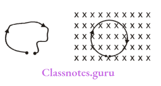
Question 15. Which of the field patterns given below is valid for electric fields as well as for magnetic fields?

NEET Physics Class 12 Chapter 6 Electromagnetic Induction Field Patterns Given Below Is Valid For Electric Field

Answer: 3

True for induced electric field and magnetic field.


NEET Physics Class 12 Chapter 1 Magnetic Field Multiple Choice Questions

Chapter 1 Magnetic Field Multiple Choice Questions Section (A): Magnet And Magnetic Field Due To A Moving Charge

Question 1. The charge on a particle is 100 times that of the electron. It is revolving in a circular path of radius 0.8 m at a frequency of 1011 revolutions per second. The magnetic field at the centre of the path will be 

  1. \(10^{-7} \mu_0\)
  2. \(\frac{10^{-7}}{\mu_0}\)
  3. \(10^{-17} \mu_0\)
  4. \(10^{-6} \mu_{}\)

Answer: 4. \(10^{-6} \mu_{}\)

Question 2. Gauss is the unit of –

  1. Magnetic induction
  2. Intensity of magnetization
  3. dipole moment
  4. None of these

Answer: 1. Magnetic induction

Question 3. A ring of radius r is uniformly charged with charge q. If the ring is rotated about its axis with angular frequency ω, then the magnetic induction at its centre will be –

  1. \(10^{-7} \times \frac{\omega}{q r}\)
  2. \(10^{-7} \times \frac{q}{\omega r}\)
  3. \(10^{-7} \times \frac{r}{q \omega}\)
  4. \(10^{-7} \times \frac{r}{q \omega}\)

Answer: 3. \(10^{-7} \times \frac{r}{q \omega}\)

Magnetic Field MCQs for NEET Physics Class 12

Question 4. If an electron revolves in the path of a circle of radius of 0.5 × 10⁻¹⁰ m at a frequency of 5 × 10¹⁵ cycles/s, the equivalent electric current in the circle is (charge of an electron 1.6 × 10 –19 C)

  1. 0.4mA
  2. 0.8mA
  3. 1.2mA
  4. 1.6mA

Answer: 4. 1.2mA

Question 5. A charged particle moves through a magnetic field in a direction perpendicular to it. Then the :

  1. Acceleration remains unchanged
  2. Velocity remains unchanged
  3. The speed of the particle remains unchanged
  4. The direction of the particle remains unchanged

Answer: 3. Speed of the particle remains unchanged

Question 6. A particle mass m, charge Q and kinetic energy T enter a transverse uniform magnetic field of B induction. After 3 s the kinetic energy of the particle will be

  1. 3T
  2. 2T
  3. T
  4. 4T

Answer: 3. T

Question 7. If a current is passed through a spring then the spring will :

  1. Expand
  2. Compress
  3. Remain same
  4. None of these

Answer: 2. Compress

Question 8. At a specific instant emission of radioactive compound is deflected in a magnetic field. The compound can emit:

  1. Electrons
  2. Protons
  3. He2+
  4. Neutrons

The emission at the instant can be 1, 2, 3

  1. 1, 2, 3,4
  2. 4
  3. 2,3

Answer: 1. 1, 2, 3

Chapter 1 Magnetic Field Multiple Choice Questions Section B: Magnetic Field Due To A Straight Wire

Question 1. A thin wire is bent to form a square loop ABCD. A battery of e.m.f 2V is connected between points A and C. The magnetic induction due to the current in the loop at centre O will-

NEET Physics Class 12 MCQs Chapter 1 Magnetic Field Point Away From The Plane Of Paper

  1. Be zero
  2. Point away from the plane of paper
  3. point along the plane of the paper
  4. Point into the plane of paper

Answer: 1. Be zero

Question 2. A small linear segment of an electric circuit is lying on the x-axis extending from \(x=-\frac{a}{2} \text { to } x=\frac{a}{2}\) and a current i is flowing in it. The magnetic induction due to the segment at a point x = a on the x-axis will be

  1. α a
  2. zero
  3. α a2
  4. \(\propto \frac{1}{\mathrm{a}}\)

Answer: 2. zero

Question 3. A current i is flowing in a straight conductor of length L. The magnetic induction at a point distant \(\frac{\mathrm{L}}{4}\) from its centre will be

  1. \(\frac{4 \mu_0 \mathrm{i}}{\sqrt{5} \pi \mathrm{L}}\)
  2. \(\frac{\mu_0 i}{2 \pi L}\)
  3. \(\frac{\mu_0 \mathrm{i}}{\sqrt{2} \mathrm{~L}}\)
  4. Zero

Answer: 1. \(\frac{4 \mu_0 \mathrm{i}}{\sqrt{5} \pi \mathrm{L}}\)

Question 4. Two insulated wires of infinite length are lying mutually at right angles to each other as shown in. Currents of 2A and 1.5A respectively are flowing in them. The value of magnetic induction at point P will be

NEET Physics Class 12 MCQs Chapter 1 Magnetic Field Value Of MagneticInduction At Point P Will Be

  1. \(2 \times 10^{-3} \mathrm{~N} / \mathrm{A}-\mathrm{m}\)
  2. \(2 \times 10^{-5} \mathrm{~N} / \mathrm{A}-\mathrm{m}\)
  3. \(1.5 \times 10^{-5} \text { tesla }\)
  4. \(2 \times 10^{-4} \mathrm{~N} / \mathrm{A}-\mathrm{m}\)

Answer: 3. \(1.5 \times 10^{-5} \text { tesla }\)

Question 5. A current of I ampere is flowing in an equilateral triangle of side a. The magnetic induction at the centroid will be

  1. \(\frac{\mu_0 \mathrm{i}}{3 \sqrt{3} \pi a}\)
  2. \(\frac{3 \mu_0 \mathrm{i}}{2 \pi \mathrm{a}}\)
  3. \(\frac{5 \sqrt{2} \mu_0 i}{3 \pi a}\)
  4. \(\frac{9 \mu_0 i}{2 \pi a}\)

Answer: 4. \(\frac{9 \mu_0 i}{2 \pi a}\)

Question 6. A current is flowing in a hexagonal coil of side a (Fig.). The magnetic induction at the centre of the coil will be

NEET Physics Class 12 MCQs Chapter 1 Magnetic Field The Magnetic Induction At The Centre Of The Coil

  1. \(\frac{3 \sqrt{3} \mu_0 \mathrm{i}}{\pi a}\)
  2. \(\frac{\mu_0 i}{3 \sqrt{3} \pi a}\)
  3. \(\frac{\mu_0 i}{\sqrt{3} \pi a}\)
  4. \(\frac{\sqrt{3} \mu_0 \mathrm{i}}{\pi a}\)

Answer: 4. \(\frac{\sqrt{3} \mu_0 \mathrm{i}}{\pi a}\)

Question 7. A straight wire of diameter 0.5 mm carrying a current of 1A is replaced by another wire of diameter 1 mm carrying the same current. The strength of the magnetic field far away is:

  1. Twice the earlier value
  2. One-half of the earlier value
  3. One-quarter of the earlier value
  4. Same as the earlier value

Answer: 4. Same as earlier value

Question 8. Two long parallel wires P and Q are held at a distance of 5m between them. If P and Q carry current of 2.5 amp and 5 amp respectively in the same direction, then the magnetic field at a point halfway between the wires is

NEET Physics Class 12 MCQs Chapter 1 Magnetic Field Two long parallel wires P and Q are held at a distance of 5m between them

  1. \(\frac{\mu_0}{\pi}\)
  2. \(\frac{\sqrt{3} \mu_0}{2 \pi}\)
  3. \(\frac{\mu_0}{2 \pi}\)
  4. \(\frac{3 \mu_0}{2 \pi}\)

Answer: 3. \(\frac{\mu_0}{2 \pi}\)

Question 9. A long straight wire carries an electric current of 2 A. The magnetic induction at a perpendicular distance of 5m from the wire will be

  1. 4 × 10⁻⁸ T
  2. 8 × 10⁻⁸ T
  3. 12 × 10–8 T
  4. 16 × 10–8 T

Answer: 2. 8 × 10⁻⁸ T

Question 10. The strength of the magnetic field at a point distant r near a long straight current-carrying wire is B. The field at a distance of r/2 will be

  1. B/2
  2. B/4
  3. 4B
  4. 2B

Answer: 4. 2B

Question 11. A wire in the form of a square of side ‘a’ carries a current ‘i’. Then the magnetic induction at the centre of the square wire is (Magnetic permeability of free space = u0)

  1. \(\frac{\mu_0 \mathrm{i}}{2 \pi \mathrm{a}}\)
  2. \(\frac{\mu_{\mathrm{o}} \mathrm{i} \sqrt{2}}{\pi \mathrm{a}}\)
  3. \(\frac{2 \sqrt{2} \mu_0 i}{\pi a}\)
  4. \(\frac{\mu_0 \mathrm{i}}{\sqrt{2} \pi a}\)

Answer: 3. \(\frac{2 \sqrt{2} \mu_0 i}{\pi a}\)

Question 12. The vector form of Biot-Savart’s law for a current carrying element is

  1. \(\mathrm{d} \overrightarrow{\mathrm{B}}=\frac{\mu_0}{4 \pi} \frac{\mathrm{Id} \vec{I} \sin \phi}{\mathrm{r}^2}\)
  2. \(\mathrm{d} \vec{B}=\frac{\mu_0}{4 \pi} \frac{I d / \times \hat{r}}{r^2}\)
  3. \(\mathrm{d} \overrightarrow{\mathrm{B}}=\frac{\mu_0}{4 \pi} \frac{\mathrm{Id} \vec{I} \times \hat{\mathrm{r}}}{\mathrm{r}^3}\)
  4. \(\mathrm{d} \overrightarrow{\mathrm{B}}=\frac{\mu_0}{4 \pi} \frac{\mathrm{Id} \vec{l} \times \hat{\mathrm{r}}}{\mathrm{r}^2}\)

Answer: 4. \(\mathrm{d} \overrightarrow{\mathrm{B}}=\frac{\mu_0}{4 \pi} \frac{\mathrm{Id} \vec{l} \times \hat{\mathrm{r}}}{\mathrm{r}^2}\)

Question 13. Two long straight wires are kept parallel. A current of 1 ampere is flowing in each wire in the same direction. The distance between them is 2r. The intensity of the magnetic field at the midpoint between them :

NEET Physics Class 12 MCQs Chapter 1 Magnetic Field Two long straight wires are kept parallel

  1. \(\frac{\mu_0 \mathrm{i}}{\mathrm{r}}\)
  2. \(\frac{4 \mu_0 \mathrm{i}}{\mathrm{r}}\)
  3. 0
  4. \(\frac{\mu_0 i}{4 r}\)

Answer: 3. 0

Question 14. Two infinitely long, thin, insulated, straight wires lie in the x-y plane along the x and y-axis respectively. Each wire carries a current I, respectively in the positive x-direction and positive y-direction. The magnetic field will be zero at all points on the straight line:

  1. y=x
  2. y=-x
  3. y=x-1
  4. y=-x+1

Answer: 1. y=x

NEET Physics Chapter 1 Magnetic Field MCQs

Question 15. Two parallel, long wires carry currents i 1 and i2 with i1 > i2. When the current is in the same direction, the magnetic field at a point midway between the wire is 10uT. If the direction of i 2 is reversed, the field becomes 30T. The ratio i1/i2 is

  1. 4
  2. 3
  3. 2
  4. 1

Answer: 3. 2

Question 16. Two long parallel wires are at a distance 2d apart. They carry steady equal currents flowing out of the plane of the paper, as shown. The variation of the magnetic field B along the XX’ is given by

NEET Physics Class 12 MCQs Chapter 1 Magnetic Field Two long parallel wires are at a distance 2d apart

Answer: 2.

Question 17. Wires 1 and 2 carrying currents i1 and i2 respectively are inclined at an angle to each other. What is the force on a small element dl of wire 2 at distance r from wire 1 (as shown in the figure) due to the magnetic field of wire 1?

NEET Physics Class 12 MCQs Chapter 1 Magnetic Field Wires 1 and 2 carrying currents i1 and i2 respectively are inclined at an angle  to each other

  1. \(\frac{\mu_0}{2 \pi \mathrm{r}} \mathrm{i}_1 \mathrm{i}_2 \mathrm{dl} \tan \theta\)
  2. \(\frac{\mu_0}{2 \pi \mathrm{r}} \mathrm{i}_1 \mathrm{i}_2 \mathrm{dl} \sin \theta\)
  3. \(\frac{\mu_0}{4 \pi r} i_1 i_2 \mathrm{dl}(\cos \theta+1)\)
  4. \(\frac{\mu_0}{4 \pi \mathrm{r}} \mathrm{i}_1 \mathrm{i}_2 \mathrm{dl} \sin \theta\)

Answer: 3. \(\frac{\mu_0}{4 \pi r} i_1 i_2 \mathrm{dl}(\cos \theta+1)\)

Question 18. A current i ampere flows along an infinitely long straight thin-walled tube, then the magnetic induction at any point inside the tube is:

  1. Infinite
  2. zero
  3. \(\frac{\mu_0}{4 \pi}, \frac{2 i}{r} \text { tesla }\)
  4. \(\frac{2 i}{r} \text { tesla }\)

Answer: 2. zero

Question 19. A long straight wire of radius a carries a steady current i. The current is uniformly distributed across its cross-section. The ratio of the magnetic field at \(\frac{a}{2}\) and 2a from axis is

  1. 1/4
  2. 4
  3. 1
  4. 1/2

Answer: 3. 1

Question 20. A current flows along the length of an infinitely long, straight, thin-walled pipe. Then :

  1. The magnetic field is zero only on the axis of the pipe
  2. The magnetic field is different at different points inside the pipe
  3. The magnetic field at any point inside the pipe is zero
  4. The magnetic field at all points inside the pipe is the same, but not zero

Answer: 3. The magnetic field at any point inside the pipe is zero

Question 21. Two identical conducting wires AOB and COD are placed at right angles to each other. The wire AOB carries an electric current I2 and COD carries a current O. The magnetic field on a point lying at a distance d from O, in a direction perpendicular to the plane of the wires AOB and COD, will be given by

  1. \(\frac{\mu_0}{2 \pi}\left(\frac{I_1+I_2}{d}\right)^{1 / 2}\)
  2. \(\frac{\mu_0}{2 \pi \mathrm{d}}\left(\mathrm{I}_1^2+\mathrm{I}_2^2\right)^{1 / 2}\)
  3. \(\frac{\mu_0}{2 \pi \mathrm{d}}\left(\mathrm{I}_1+\mathrm{I}_2\right)\)
  4. \(\frac{\mu_0}{2 \pi \mathrm{d}}\left(\mathrm{I}_1^2+\mathrm{I}_2^2\right)\)

Answer: 2. \(\frac{\mu_0}{2 \pi \mathrm{d}}\left(\mathrm{I}_1^2+\mathrm{I}_2^2\right)^{1 / 2}\)

Chapter 1 Magnetic Field Multiple Choice Questions Section C: Magnetic Field Due To A Circular Loop

Question 1. An electric current i is flowing in a circular coil of radius a. At what distance from the center on the axis of the coil will the magnetic field be 1/8th of its value at the center?

  1. 3a
  2. \(\sqrt{3} a\)
  3. \(\frac{a}{3}\)
  4. \(\frac{a}{\sqrt{3}}\)

Answer: 2. 3a

Question 2. The ratio of magnetic inductions at the center of a circular coil of radius a and on its axis at a distance equal to its radius will be

  1. \(\frac{1}{\sqrt{2}}\)
  2. \(\frac{\sqrt{2}}{1}\)
  3. \(\frac{1}{2 \sqrt{2}}\)
  4. \(\frac{2 \sqrt{2}}{1}\)

Answer: 1. \(\frac{1}{\sqrt{2}}\)

Question 3. A wire loop PQRSP is constructed by joining two semi-circular coils of radii r1 and r2 respectively as shown in Fig. Current i is flowing in the loop. The magnetic induction at point O will be

NEET Physics Class 12 MCQs Chapter 1 Magnetic Field A wire loop PQRSP is constructed by joining two semi circular coils of radii

  1. \(\frac{\mu_0 i}{4}\left[\frac{1}{r_1}-\frac{1}{r_2}\right]\)
  2. \(\frac{\mu_0 \mathrm{i}}{4}\left[\frac{1}{r_1}+\frac{1}{r_2}\right]\)
  3. \(\frac{\mu_0 i}{2}\left[\frac{1}{r_1}-\frac{1}{r_2}\right]\)
  4. \(\frac{\mu_0 \mathrm{i}}{2}\left[\frac{1}{r_1}+\frac{1}{r_2}\right]\)

Answer: 3. \(\frac{\mu_0 i}{2}\left[\frac{1}{r_1}-\frac{1}{r_2}\right]\)

Question 4. The magnetic field on the axis of a current-carrying circular coil of radius at a distance 2a from its centre will be

  1. \(\frac{\mu_0 i}{2}\)
  2. \(\frac{\mu_0 i}{10 \sqrt{5} a}\)
  3. \(\frac{\mu_0 \mathrm{i}}{4 \mathrm{a}}\)
  4. \(\mu_0 i\)

Answer: 2. \(\frac{\mu_0 i}{10 \sqrt{5} a}\)

Question 5. The use of Helmholtz coils is to produce –

  1. Uniform magnetic field
  2. Non-uniform magnetic field
  3. Varying magnetic field
  4. Zero magnetic field

Answer: 1. Uniform magnetic field

Question 6. Two similar coils of radius R and several turns N are lying concentrically with their planes at right 3 angles to each other. The currents flowing in them are I and I respectively. The resultant magnetic induction at the centre will be (in Wb/m2).

  1. \(\frac{\mu_0 \mathrm{NI}}{2 \mathrm{R}}\)
  2. \(\frac{\mu_0 \mathrm{NI}}{\mathrm{R}}\)
  3. \(\sqrt{3} \mu_0 \frac{\mathrm{NI}}{2 \mathrm{R}}\)
  4. \(\sqrt{5} \frac{\mu_0 \mathrm{NI}}{2 \mathrm{R}}\)

Answer: 2. \(\frac{\mu_0 \mathrm{NI}}{\mathrm{R}}\)

Question 7. Two similar coils are kept mutually perpendicular such that their centres coincide. At the centre, find the ratio of the magnetic field due to one coil and the resultant magnetic field through both coils, if the same current is flown:

  1. \(1: \sqrt{2}\)
  2. 1:2
  3. 1:3
  4. \(\sqrt{3}: 1\)

Answer: 1. \(1: \sqrt{2}\)

Question 8. A coil of one turn is made of a wire of a certain length and then from the same length a coil of two turns is made. If the same current is passed in both cases, then the ratio of the magnetic induction at their centres will be

  1. 2:1
  2. 1:4
  3. 4:1
  4. 1:2

Answer: 2. 1:4

Question 9. Magnetic field due to 0.1A current flowing through a circular coil of radius 0.1 m and 1000 turns at the centre of the coil is

  1. 0.2T
  2. 2 ×10⁻⁴ T
  3. 6.28 ×10⁻⁴ T
  4. 9.8 ×10⁻⁴ T

Answer: 3. 6.28 ×10⁻⁴ T

Question 10. Magnetic field due to a ring having n turns at a distance x from the centre on its axis is proportional to (if r = radius of the ring)

  1. \(\frac{r}{\left(x^2+r^2\right)}\)
  2. \(\frac{r^2}{\left(x^2+r^2\right)^{3 / 2}}\)
  3. \(\frac{n r^2}{\left(x^2+r^2\right)^{3 / 2}}\)
  4. \(\frac{n^2 r^2}{\left(x^2+r^2\right)^{3 / 2}}\)

Answer: 3. \(\frac{n r^2}{\left(x^2+r^2\right)^{3 / 2}}\)

Question 11. A circular arc of wire subtends an angle \(\frac{\pi}{2}\) at the centre. If it carries a current I and its radius of curvature is R, then the magnetic field at the centre of the arc is

  1. \(\frac{\mu_0 I}{8 R}\)
  2. \(\frac{\mu_0 \mathrm{I}}{\mathrm{R}}\)
  3. \(\frac{\mu_0 I}{2 R}\)
  4. \(\frac{\mu_0 I}{4 R}\)

Answer: 1. \(\frac{\mu_0 I}{8 R}\)

Question 12. The magnetic field of a given length of wire carrying a current for a single-turn circular coil at the centre is B, then its value for two turns for the same wire, when the same current passes through it, is

  1. \(\frac{B}{4}\)
  2. \(\frac{B}{2}\)
  3. 2B
  4. 4B

Answer: 4. 4B

Question 13. If in a circular coil A of radius R, current i is flowing and in another coil B of radius 2R a current 2i is flowing, then the ratio of the magnetic fields, BA and BB produced at the centre by them will be :

  1. 1
  2. 2
  3. 1/2
  4. 4

Answer: 1. 1

Question 14. A long wire carries a steady current. It is bent into a circle of one turn and the magnetic field at the centre of the coil is B. It is then bent into a circular loop of n turns. The magnetic field at the centre of the coil will be:

  1. nB
  2. n2B
  3. 2nB
  4. 2n2B

Answer: 2. n2B

Question 15. The magnetic field due to a current carrying circular loop of radius 3 cm at a point on the axis at a distance of 4 cm from the centre is 54 T. What will be its value at the centre of the loop?

  1. 250 μT
  2. 150 μT
  3. 125 μT
  4. 75μT

Answer: 1. 250 μT

Question 16. A long solenoid has 200 turns per cm and carries a current i. The magnetic field at its centre is 6.28×10⁻² Weber/m2. Another long solenoid has 100 turns per cm and it carries a current i/3. The value of the magnetic field at its centre is

  1. 1.05 × 10⁻⁴ Weber/m2
  2. 1.05 × 10⁻² Weber/m2
  3. 1.05 × 10⁻⁵ Weber/m2
  4. 1.05 × 10¹⁰–3 Weber/m2

Answer: 2. 1.05 × 10⁻² Weber/m2

Chapter 1 Magnetic Field Multiple Choice Questions Section D: Magnetic Field Due To A Straight Wire And Circular Arc

Question 1. The magnetic induction at center O due to the arrangement shown in fig.

NEET Physics Class 12 MCQs Chapter 1 Magnetic Field The magnetic induction at centre O

  1. \(\frac{\mu_0 i}{4 \pi r}(1+\pi)\)
  2. \(\frac{\mu_0 i}{4 \pi r}\)
  3. \(\frac{\mu_0 i}{4 \pi r}(1-\pi)\)
  4. \(\frac{\mu_0 i}{r}\)

Answer: 1. \(\frac{\mu_0 i}{4 \pi r}(1+\pi)\)

Question 2. A current of 30 amp. is flowing in a conductor as shown in Fig. The magnetic induction at point O will be

NEET Physics Class 12 MCQs Chapter 1 Magnetic Field A current of 30 amp

  1. 1.5 tesla
  2. 1.5π × 10–4 Tesla
  3. zero
  4. O.15 Tesla

Answer: 2. 1.5π × 10–4 Tesla

Question 3. The magnetic induction at centre O in the following figure will be

NEET Physics Class 12 MCQs Chapter 1 Magnetic Field The magnetic induction at centre O.

  1. \(\frac{\mu_0 i \alpha}{4 \pi}\left(\frac{1}{r_1}-\frac{1}{r_2}\right) \odot\)
  2. \(\frac{\mu_0 i \alpha}{4 \pi}\left(\frac{1}{r_1}+\frac{1}{r_2}\right) \odot\)
  3. \(\frac{\mu_0 i \alpha}{2 \pi}\left[\frac{1}{r_1}-\frac{1}{r_2}\right] \otimes\)
  4. \(\frac{\mu_0 i \alpha}{2 \pi}\left[\frac{1}{r_1}+\frac{1}{r_2}\right]\)

Answer: 1. \(\frac{\mu_0 i \alpha}{4 \pi}\left(\frac{1}{r_1}-\frac{1}{r_2}\right) \odot\)

Question 4. Two circular coils 1 and 2 are made from the same wire but the radius of the 1st coil is twice that of the 2nd coil. What is the ratio of the potential difference applied across them so that the magnetic field at their centres is the same:

  1. 3
  2. 4
  3. 6
  4. 2

Answer: 2. 4

Chapter 1 Magnetic Field Multiple Choice Questions Section (E): Magnetic Field Due To A Cylinder, Large Sheet, Solenoid, Toroid And Ampere’s Law

Question 1. When the number of turns in a toroidal coil is doubled, then the value of magnetic flux density will become-

  1. Four times
  2. Eight times
  3. Half
  4. Double

Answer: 2. Eight times

Question 2. The length of a solenoid is 0.1 m and its diameter is very small. A wire is wound over it in two layers. The number of turns in the inner layer is 50 and that on the outer layer is 40. The strength of the current flowing in two layers is in the same direction and is 3 ampere. The magnetic induction in the middle of the solenoid will be

  1. 3.4 × 10⁻³ Tesla
  2. 3.4 × 10⁻³ Gauss
  3. 3.4 × 10³ Tesla
  4. 3.4 × 10³ Gauss

Answer: 4. 3.4 × 10³ Gauss

Question 3. The magnetic field inside a long solenoid is –

  1. Infinite
  2. Zero
  3. Uniform
  4. Non-uniform

Answer: 1. Infinite

Question 4. The correct curve between the magnetic induction along the axis of a long solenoid due to current flow I in it and distance x from one end is

NEET Physics Class 12 MCQs Chapter 1 Magnetic Field The correct curve between the magnetic induction

Answer: 2.

NEET Physics Class 12 MCQs Chapter 1 Magnetic Field The correct curve between the magnetic induction 4

Question 5. A long solenoid has 200 turns per cm and carries a current of 2.5 amp. The magnetic field at its centre is μ0 = 4π × 10–7 weber/amp-m]:

  1. 3.14 × 10⁻² weber/m²
  2. 6.28 × 10⁻² weber/m²
  3. 9.42 × 10⁻² weber/m²
  4. 12.56 × 10⁻² weber/m²

Answer: 1. 3.14 × 10⁻² weber/m²

Question 6. In a coaxial, straight cable, the central conductor and the outer conductor carry equal currents in opposite directions. The magnetic field is zero.

NEET Physics Class 12 MCQs Chapter 1 Magnetic Field Inside the inner conductor

  1. Outside the cable
  2. Inside the inner conductor
  3. Inside the outer conductor
  4. In between the two conductors.

Answer: 2. Inside the inner conductor

Question 7. A wire is wound on a long rod of material of relative permeability r = 4000 to make a solenoid. If the current through the wire is 5 A and the number of turns per unit length is 1000 per metre, then the magnetic field inside the solenoid is:

  1. 25.12 mT
  2. 12.56 m T
  3. 12.56 T
  4. 25.12 T

Answer: 1. 25.12 mT

Question 8. A cylindrical wire of radius R carries current I uniformly distributed over its cross-section. If a circular \(\int \vec{B} \cdot \vec{d}\) loop of radius ‘ r ‘ is taken as a campervan loop, then the variation value over this loop with radius ‘ r ‘ of the loop will be best represented by

NEET Physics Class 12 MCQs Chapter 1 Magnetic Field A cylindrical wire of radius R is carrying current i uniformly distributed over its cross-section

Answer: 2.

NEET Physics Class 12 MCQs Chapter 1 Magnetic Field A cylindrical wire of radius R is carrying current i uniformly distributed over its cross-section.

Question 9. A current flows along the length of an infinitely long, straight, thin-walled pipe. Then

  1. The magnetic field at all points inside the pipe is the same, but not zero
  2. The magnetic field at any point inside the pipe is zero
  3. The magnetic field is zero only on the axis of the pipe
  4. The magnetic field is different at different points inside the pipe.

Answer: 3. The magnetic field is zero only on the axis of the pipe

Question 10. A long solenoid carrying a current produces a magnetic field B along its axis. If the current is doubled and the number of turns per cm is halved, the new value of the magnetic field is:

  1. 2B
  2. 4B
  3. B/2
  4. B

Answer: 3. B/2

Question 11. A long, thick straight conductor of radius R carries current I uniformly distributed in its cross-section area. The ratio of the energy density of the magnetic field at a distance R/2 from the surface inside the conductor and outside the conductor is:

  1. 1: 16
  2. 1: 1
  3. 1: 4
  4. 9/16

Answer: 4. 9/16

Question 12. A coaxial cable is made up of two conductors. The inner conductor is solid and is of radius R1 & the outer conductor is hollow of inner radius R2 and outer radius R3. The space between the conductors is filled with air. The inner and outer conductors are carrying currents of equal magnitudes and in opposite directions. Then the variation of the magnetic field with distance from the axis is best plotted as:

NEET Physics Class 12 MCQs Chapter 1 Magnetic Field A coaxial cable is made up of two conductors.

Answer: 3.


NEET Physics Class 12 MCQs Chapter 1 Magnetic Field A coaxial cable is made up of two conductors.3


Chapter 1 Magnetic Field Multiple Choice Questions Section (F): Magnetic Force On A Charge

Question 1. When a charged particle moves at right angles to a magnetic field then which of the following quantities changes-

  1. Energy
  2. Momentum
  3. Speed
  4. All Of Above

Answer: 2. Momentum

Question 2. A proton, a neutron, and an α-particle are accelerated through the same potential difference and then they enter a uniform normal magnetic field. If the radius of the circular path of the proton is 8 cm then the radius of the circular path of the deuteron will be

  1. 11.31 cm
  2. 22 cm
  3. 5 cm
  4. 2.5 cm

Answer: 1. 11.31 cm

Question 3. A proton and an α-particle enter a uniform magnetic field at right angles to it with the same velocity. The period of α the particle as compared to that of the proton, will be

  1. Four Times
  2. Two Times
  3. Half
  4. One Fourth

Answer: 2. Four Times

Question 4. A charged particle with charge q is moving in a uniform magnetic field. If this particle makes some angle (0 < θ < 180º) with the magnetic field then its path will be –

  1. Circular
  2. Straight Line
  3. Helical
  4. Parabolic

Answer: 3. Helical

Question 5. If a positively charged particle is moving as shown in the fig., then it will get deflected due to the magnetic field towards

NEET Physics Class 12 MCQs Chapter 1 Magnetic Field If a positively charged particle

  1. +x direction
  2. +y direction
  3. –x direction
  4. +z direction

Answer: 4. +z direction

Question 6. Which of the following particles will experience maximum magnetic force (magnitude) when projected with the same velocity perpendicular to a magnetic field?

  1. Electron
  2. Proton
  3. He+
  4. Li++

Answer: 4. Li++

Question 7. An electric current enters and leaves a uniform circular wire of radius through diametrically opposite points. A charged particle q moving along the axis of the circular wire passes through its center at speed υ. The magnetic force acting on the particle when it passes through the center has a magnitude.

  1. \(q v \frac{\mu_0 i}{2 a}\)
  2. \(\mathrm{q} v \frac{\mu_0 \mathrm{i}}{2 \pi \mathrm{a}}\) m
  3. \(q v \frac{\mu_0 i}{a}\)
  4. Zero

Answer: 4. Zero

Question 8. A charged particle is moved along a magnetic field line. The magnetic force on the particle is

  1. Along its velocity
  2. Opposite to its velocity
  3. Perpendicular to its velocity
  4. Zero.

Answer: 4. Zero.

Question 9. Two particles X and Y having equal charges, after being accelerated through the same potential difference, enter a region of uniform magnetic field and describe circular paths of radii R1 and R2 respectively. The ratio of the masses of X to that of Y.

  1. \(\left(\frac{R_1}{R_2}\right)^{1 / 2}\)
  2. \(\frac{R_2}{R_1}\)
  3. \(\left(\frac{R_1}{R_2}\right)^2\)
  4. \(\frac{R_1}{R_2}\)

Answer: 3. \(\left(\frac{R_1}{R_2}\right)^2\)

Question 10. A negatively charged particle falling freely under gravity enters a region having a uniform horizontal magnetic field pointing toward the north. The particle will be deflected towards

  1. East
  2. West
  3. North
  4. South

Answer: 2. West

Question 11. A proton of mass m and charge q enters a magnetic field B with a velocity v at an angle θ with the direction of B. The radius of curvature of the resulting path is

  1. \(\frac{m v}{q B}\)
  2. \(\frac{m v \sin \theta}{q B}\)
  3. \(\frac{\mathrm{mv}}{\mathrm{qB} \sin \theta}\)
  4. \(\frac{m v \cos \theta}{q B}\)

Answer: 3. \(\frac{\mathrm{mv}}{\mathrm{qB} \sin \theta}\)

Question 12. Two particles A and B of masses m A and mB respectively and having the same charge are moving in a plane. A uniform magnetic field exists perpendicular to this plane. The speeds of the particles are vA and v B respectively and the trajectories are as shown in the figure. Then

NEET Physics Class 12 MCQs Chapter 1 Magnetic Field A uniform magnetic field exists perpendicular to this plane

  1. mAvA < mBvB
  2. mAvA > mBvB
  3. mA < mB and vA < vB
  4. mA = mB and vA = vB

Answer: 2. mAvA > mBvB

Question 13. A charged particle is released from rest in a region of steady and uniform electric and magnetic fields that are parallel to each other. The particle will move in a

  1. Straight line
  2. Circle
  3. Helix
  4. Cycloid

Answer: 1. Straight line

Question 14. A particle of mass M and charge Q moving with velocity describes a circular path of radius R when subjected to a uniform transverse magnetic field of induction B. The work done by the field when the particle completes one full circle is

  1. \(\left(\frac{m v^2}{R}\right) 2 \pi R\)
  2. Zero
  3. BQ.2πR
  4. BQv.2πR

Answer: 2. Zero

Question 15. An electron moves with a velocity of 1 × 10³ m/s in a magnetic field of induction 0.3 T at an angle of 30°. If em of electron is 1.76 × 10¹¹ C/kg, the radius of the path is nearly:

  1. 10–9 meter
  2. 2 × 10⁻⁸ meter
  3. 10–8 meter
  4. 10–10 meter

Answer: 3. 10–8 meter

Question 16. A charged particle of charge q and mass m enters perpendicularly in a magnetic field. The kinetic energy of the particle is E; then the frequency of rotation is :

  1. \(\frac{q B}{m \pi}\)
  2. \(\frac{q B}{2 \pi m}\)
  3. \(\frac{\mathrm{qBE}}{2 \pi \mathrm{m}}\)
  4. \(\frac{\mathrm{qB}}{2 \pi \mathrm{E}}\)

Answer: 2. \(\frac{q B}{2 \pi m}\)

Question 17. A Beam Of Particles With a Specific Charge of 108 C/Kg Is Entering With Velocity 3 × 10⁵ M/S By Making An Angle Of 30° With The Uniform Magnetic Field Of 0.3 Tesla. Radius Of Curvature Of Path Of Particle Is

  1. 0.5 Cm
  2. 0.02 Cm
  3. 1.25 Cm
  4. 2 Cm

Answer: 4. 0.02 Cm

Question 18. If An Electron Enters A Magnetic Field With Its Velocity Pointing In The Same Direction As The Magnetic Field, Then:

  1. The Electron Will Turn To Its Right
  2. The Electron Will Turn To Its Left
  3. The Velocity Of The Electron Will Increase
  4. The Velocity Of The Electron Will Remain Unchanged

Answer: 4. The Velocity Of The Electron Will Remain Unchanged

Question 19. A Charge Of 1c Is Moving In A Perpendicular Magnetic Field Of 0.5 Tesla With A Velocity Of 10 M/Sec. Force Experienced Is:

  1. 5 N
  2. 10 N
  3. 0.5 N
  4. 0 N

Answer: 1. 5 N

Question 20. An Electron Accelerated By 200 V, Enters A Magnetic Field. If Its Velocity Is 8.4 × 10 6 M/Sec. Then (E/M) For It Will Be : (In C/Kg)

  1. 1.75 × 10¹⁰
  2. 1.75 × 10¹¹
  3. 1.75 × 10⁹
  4. 1.75 × 10⁶

Answer: 2. 1.75 × 10¹¹

Question 21. A Charge Q Is Moving In A Uniform Magnetic Field. The Magnetic Force Acting On It Does Not Depend Upon

  1. Charge
  2. Mass
  3. Velocity
  4. Magnetic Field

Answer: 2. Mass

Question 22. An Electron Is Travelling In the East Direction And A Magnetic Field Is Applied In an Upward Direction, the electron Will Deflect Towards

  1. South
  2. North
  3. West
  4. East

Answer: 2. North

Question 23. A Proton Enters A Magnetic Field With Velocity Parallel To The Magnetic Field. The Path Followed By The Proton Is A

  1. Circle
  2. Parabola
  3. Helix
  4. Straight Line

Answer: 4. Straight Line

Question 24. An electron (mass = 9.0 × 10⁻³¹ kg and charge = 1.6 × 10⁻¹⁹ coulomb) is moving in a circular orbit in a magnetic field of 1.0 × 10⁻⁴ Weber/m2. Its period of revolution is:

  1. 3.5 × 10⁻⁷ second
  2. 7.0 × 10⁻⁷ seconds
  3. 1.05 × 10⁻⁶ seconds
  4. 2.1 × 10—6 second

Answer: 1. 3.5 × 10⁻⁷ second

Question 25. A particle of mass 0.6 g and having a charge of 25 nC is moving horizontally with a uniform velocity of 1.2 × 10⁴ ms–1 in a uniform magnetic field, then the value of the minimum magnetic induction is (g = 10ms–2)

  1. Zero
  2. 10 T
  3. 20 T
  4. 200 T

Answer: 3. 20 T

Question 26. An electron is moving with velocity in the direction of the magnetic field, then the force acting on the electron is:-

  1. Zero
  2. \(\mathrm{e}(\overrightarrow{\mathrm{v}} \times \overrightarrow{\mathrm{B}})\)
  3. \(\mathrm{e}(\overrightarrow{\mathrm{B}} \times \overrightarrow{\mathrm{v}})\)
  4. 200 Joule

Answer: 1. \(\mathrm{e}(\overrightarrow{\mathrm{v}} \times \overrightarrow{\mathrm{B}})\)

Question 27. A Vertical Wire Carries A Current In an Upward Direction. An Electron Beam Sent Horizontally Towards The Wire Will Be Deflected (Gravity Free Space)

  1. Towards Right
  2. Towards Left
  3. Upwards
  4. Downwards

Answer: 3. Upwards

Question 28. If An Electron And A Proton Having the Same Momentum Enter Perpendicularly To A Magnetic Field, Then :

  1. Curved Path Of Electron And Proton Will Be Same (Ignoring The Sense Of Revolution)
  2. They Will Move Undeflected
  3. Curved Path Of Electron Is More Curved Than That Of Proton
  4. Path Of Proton Is More Curved

Answer: 1. The Curved Path Of the Electron And Proton Will Be the Same (Ignoring The Sense Of Revolution)

Question 29. A Magnetic Needle Is Kept In A Non-Uniform Magnetic Field. It Experiences :

  1. A Torque But Not A Force
  2. Neither A Force Nor A Torque
  3. A Force And A Torque
  4. A Force But Not A Torque

Answer: 3. A Force And A Torque

Question 30. Two thin, long, parallel wires, separated by a distance ‘d’ carry a current of ‘i’ A in the same direction. They will:

  1. Attract each other with a force of \(\frac{\mu_0 i^2}{(2 \pi d)}\)
  2. Repel, each other with a force of \(\frac{\mu_0 i^2}{(2 \pi d)}\)
  3. Attract each other with a force of \(\frac{\mu_0 i^2}{\left(2 \pi d^2\right)}\)
  4. Repel each other with a force of \(\frac{\mu_0 i^2}{\left(2 \pi d^2\right)}\)

Answer: 1. Attract each other with a force of \(\frac{\mu_0 i^2}{(2 \pi d)}\)

Question 31. A uniform electric field and a uniform magnetic field are acting along the same direction in a certain region. If an electron is projected along the direction of the fields with a certain velocity, then :

  1. Its velocity will decrease
  2. Its velocity will increase
  3. It will turn toward the right of direction of motion
  4. It will turn towards the left of the direction of motion.

Answer: 1. Its velocity will decrease

Question 32. A charged particle of mass m and charge q travels on a circular path of radius r that is perpendicular to a magnetic field B. The time taken by the particle to complete one revolution is:

  1. \(\frac{2 \pi m q}{B}\)
  2. \(\frac{2 \pi q^2 B}{B}\)
  3. \(\frac{2 \pi q B}{m}\)
  4. \(\frac{2 \pi m}{q B}\)

Answer: 4. \(\frac{2 \pi m}{q B}\)

Question 33. In a region, steady and uniform electric and magnetic fields are present. These two fields are parallel to each other. A charged particle is released from rest in this region. The path of the particle will be a:

  1. Circle
  2. Helix
  3. Straight line
  4. Ellipse

Answer: 3. Straight line

Question 34. A charged particle with charge q enters a region of constant, uniform, and mutually orthogonal fields B E B v and with a velocity perpendicular to both and, and comes out without any change in v magnitude or direction of. Then :

  1. \(\overrightarrow{\mathrm{v}}=\overrightarrow{\mathrm{E}} \times \overrightarrow{\mathrm{B}} / \mathrm{B}^2\)
  2. \(\vec{v}=\vec{E} \times \vec{E} / B^2\)
  3. \(\overrightarrow{\mathrm{V}}=\overrightarrow{\mathrm{B}} \times \overrightarrow{\mathrm{E}} / \mathrm{E}^2\)

Answer: 1. \(\overrightarrow{\mathrm{v}}=\overrightarrow{\mathrm{E}} \times \overrightarrow{\mathrm{B}} / \mathrm{B}^2\)

Question 35. A charged particle moves through a magnetic field perpendicular to its direction. Then :

  1. The momentum changes but the kinetic energy is constant
  2. Both momentum and kinetic energy of the particle are not constant
  3. Both, the momentum and kinetic energy of the particle are constant
  4. Kinetic energy changes but the momentum is constant

Answer: 1. The momentum changes but the kinetic energy is constant

Question 36. A α particle is accelerated by a potential difference of 10 4V. Find the change in its direction of motion, if it enters normally in a region of thickness 0.1 m having transverse magnetic induction of 0.1 Tesla. (Given: mass of -particle is equal to 6.4 × 10⁻²⁷ kg) 

  1. 15º
  2. 30º
  3. 45º
  4. 60º

Answer: 2. 15º

Question 37. The figure shows a convex lens of focal length 10 cm lying in a uniform magnetic field B of magnitude 1.2 T parallel to its principal axis. A particle having a charge of 2.0 × 10 –3 C and a mass of 2.0 × 10⁻⁵ kg is projected perpendicular to the plane of the diagram with a speed of 4.8 m/s.

The particle moves along a circle with its center on the principal axis at a distance of 15 cm from the lens. The axis of the lens and the circle are the same. Show that the image of the particle goes along a circle and find the radius of that circle.

NEET Physics Class 12 MCQs Chapter 1 Magnetic Field The Change In Its Direction Of Motion

  1. 8 cm
  2. 16 cm
  3. 32 cm
  4. 64 cm

Answer: 1. 8 cm

Class 12 NEET Physics Magnetic Field Multiple Choice Questions

Chapter 1 Magnetic Field Multiple Choice Questions Section (G): Electric And Magnetic Force On A Charge

Question 1. Uniform electric and magnetic fields are produced in the same direction. An electron moves in such a way that its velocity remains in the direction of the electric field. The electron will –

  1. Turn towards left
  2. Turn towards right
  3. Get decelerated
  4. Get accelerated

Answer: 2. Turn towards right

Question 2. In the following fig., three paths of ∝ particles crossing a nucleus N are shown. The correct path is

NEET Physics Class 12 MCQs Chapter 1 Magnetic Field Three Paths Of Particle Crossing A Nucleus N

  1. a and c
  2. a and b
  3. a, b and c
  4. only a

Answer: 1. a and c

Question 3. The distance between the plates of a parallel plate condenser is 4 mm and the potential difference between them is 200V. The condenser is placed in a magnetic field B. An electron is projected vertically upwards parallel to the plates with a velocity of 106 m/s. The electron passes undeviated through the space between the plates. The magnitude and direction of magnetic field B will be –

NEET Physics Class 12 MCQs Chapter 1 Magnetic Field The magnitude and direction of magnetic field B will be

  1. 0.05T
  2. 0.02T
  3. 0.05 T Outward
  4. 0.02T Outward

Answer: 1. 0.05T

Question 4. A beam of protons enters a uniform magnetic field of 0.3T with a velocity of 4 × 10 5m/s in a direction making an angle of 60º with the direction of the magnetic field. The path of motion of the particle will be

  1. Circular
  2. Straight Line
  3. Spiral
  4. Helical

Answer: 4. Helical

Question 5. In the above question, the radius of the path of the particle will be

  1. 12.0m
  2. 1.2m
  3. 0.12m
  4. 0.012m

Answer: 4. 0.012m

Question 6. In the above question, the pitch of the helix will be

  1. 4.37 m
  2. 0.437 m
  3. 0.0437 m
  4. 0.00437 m

Answer: 3. 0.0437 m

Question 7. In a certain region of space electric field and magnetic field are perpendicular to each other and in B E an electron enters in region perpendicular to the direction of both and moves undeflected, The velocity of the electron is:

  1. \(\frac{|\vec{E}|}{|\vec{B}|}\)
  2. \(\vec{E} \times \vec{B}\)
  3. \(\frac{|\vec{B}|}{|\vec{E}|}\)
  4. \(\frac{|\vec{B}|}{|\vec{E}|}\)

Answer: 1. \(\frac{|\vec{E}|}{|\vec{B}|}\)

Question 8. A charged particle with velocity 2 × 10³ m/s passed undeflected through an electric and perpendicular magnetic field. The magnetic field is 1.5 Tesla. Find electric field intensity.

  1. 2 × 10³ N/C
  2. 1.5 × 10³ N/C
  3. 3 × 10³ N/C
  4. 4/3 × 10–3 N/C

Answer: 3. 3 × 10³ N/C

Question 9. A charged particle moves in a region having a uniform magnetic field and a parallel, uniform electric field. At some instant, the velocity of the particle is perpendicular to the field direction. The path of the particle will be

  1. A Straight Line
  2. A Circle
  3. A Helix With Uniform Pitch
  4. A Helix With Nonuniform Pitch.

Answer: 4. A Helix With Nonuniform Pitch.

Question 10. In a mass spectrometer used for measuring the masses of ions, the ions are initially accelerated by an electric potential V and then made to describe semicircular paths of radius R using a magnetic field B. If the charge on the ions V and B are kept constant, the ratio mass of the ion will be proportional to:

  1. \(\frac{1}{R}\)
  2. \(\frac{1}{\mathrm{R}^2}\)
  3. R2
  4. R

Answer: 2. \(\frac{1}{\mathrm{R}^2}\)

Question 11. A charge ‘q’ moves in a region where the electric field and magnetic field both exit, then the force on it is:

  1. \(\frac{1}{R}\)
  2. \(\frac{1}{R^2}\)
  3. R2
  4. R

Answer: 2. \(\frac{1}{R^2}\)

Question 12. A very long straight wire carries a current I. At the instant when a charge +Q at point P has velocity, as shown, the force on the charge is:-

NEET Physics Class 12 MCQs Chapter 1 Magnetic Field A very long straight wire carries a current I

  1. Opposite To Ox
  2. Along Ox
  3. Opposite To Oy
  4. Along Oy

Answer: 4. Along Oy

Question 13. An electron moves in a circular orbit with a uniform speed v. It produces a magnetic field B at the center of the circle. The radius of the circle is proportional to :

  1. \(\frac{B}{v}\)
  2. \(\frac{v}{B}\)
  3. \(\sqrt{\frac{v}{B}}\)
  4. \(\sqrt{\frac{B}{v}}\)

Answer: 3. \(\sqrt{\frac{v}{B}}\)

Question 14. When a charged particle moving with velocity is subjected to a magnetic field of induction, the force on it is non-zero. This implies that:

  1. Angle Between And Is Necessarily 90°
  2. Angle Between And Can Have Any Value Other Than 90°
  3. Angle Between And Can Have Any Value Other Than Zero And 180°
  4. Angle Between And Is Either Zero Or 180°

Answer: 3. Angle Between And Can Have Any Value Other Than Zero And 180°

Question 15. Under the influence of a uniform magnetic field a charged particle is moving in a circle of radius R with constant speed v. The period of the motion :

  1. Depends On V And Not On R
  2. Depends On Both R And V
  3. Is Independent Of Both R And V
  4. Depends On R And Not On V

Answer: 3. Is Independent Of Both R And V

Question 16. In a mass spectrometer used for measuring the masses of ions, the ions are initially accelerated by an electric potential V and then made to describe semicircular paths of radius R using a describe semicircular paths of radius R using a magnetic field B. If V and B are kept constant, the ratio. \(\left(\frac{\text { charge on the ion }}{\text { mass of the ion }}\right)\) will be proportional to:

  1. \(\frac{1}{R}\)
  2. \(\frac{1}{R^2}\)
  3. R2
  4. R

Answer: 2. \(\frac{1}{R^2}\)

Question 17. A beam of electrons passes undeflected through mutually perpendicular electric and magnetic fields. If the electric field is switched off, and the same magnetic field is maintained, the electrons move:

  1. In an elliptical orbit
  2. In a circular orbit
  3. Along a parabolic path
  4. Along a straight line

Answer: 2. In a circular orbit

Question 18. A magnetic line of force inside a bar magnet:

  1. Are From North-Pole To South-Pole Of The Magnet
  2. Do Not Exist
  3. Depend Upon The Area Of Cross-Section Of The Bar Magnet
  4. Are From South-Pole To North-Pole Of The Magnet

Answer: 4. Are From South-Pole To North-Pole Of The Magnet

Question 19. An experimenter’s diary reads as follows; “a charged particle is projected in a magnetic field of \((7.0 \hat{i}-3.0 \hat{j}) \times 10^{-3} \mathrm{~T}\). The acceleration of the particle is found to be \((x \hat{i}+7.0 \hat{j}) \times 10^{-6} \mathrm{~m} / \mathrm{s}^2\). Find the value of x.

  1. 2
  2. 4
  3. 3
  4. 1

Answer: 3. 3

Chapter 1 Magnetic Field Multiple Choice Questions Section (H): Magnetic Force On A Current Carrying Wire

Question 1. A 0.5 m long straight wire in which a current of 1.2 A is flowing is kept a right angle to a uniform magnetic field of 2.0 tesla. The force acting on the wire will be –

  1. 2N
  2. 2.4 N
  3. 1.2 N
  4. 3 N

Answer: 3. 1.2 N

Question 2. Two parallel wires P and Q carry electric currents of 10 A and 2A respectively in mutually opposite directions. The distance between the wires is 10 cm. If the wire P is of infinite length and wire Q is 2m long, then the force acting Q will be –

  1. 4 × 10⁻⁵ N
  2. 8 × 10⁻⁵ N
  3. 4 × 10⁵ N
  4. 0 N

Answer: 1. 4 × 10⁻⁵ N

Question 3. A current of 2A is flowing in a wire of length 50 cm. If this wire is lying in a uniform magnetic field of 5 × 10⁻⁴ N/A-m making an angle of 60º with the field, then the force acting on the wire will be –

  1. 4.33 × 10⁻⁴ N
  2. 4N
  3. 4 dyne
  4. zero

Answer: 1. 4.33 × 10⁻⁴ N

Question 4. A current-carrying, straight wire is kept along the axis of a circular loop carrying a current. The straight wire

  1. Will Exert An Inward Force On The Circular Loop
  2. Will Exert An Outward Force On The Circular Loop
  3. Will Not Exert Any Force On The Circular Loop
  4. Will Exert A Force On The Circular Loop Parallel To Itself.

Answer: 4. Will Exert A Force On The Circular Loop Parallel To Itself.

Question 5. A proton beam is going from north to south and an electron beam is going from south to north. Neglecting the earth’s magnetic field, the electron beam will be deflected.

  1. Towards The Proton Beam
  2. Away From The Proton Beam
  3. Away From The Electron Beam
  4. None Of These

Answer: 1. Towards The Proton Beam

Question 6. Two parallel wires carrying currents in the same direction attract each other because of

  1. Potential Difference Between Them
  2. Mutual Inductance Between Them
  3. Electric Force Between Them
  4. Magnetic Force Between Them

Answer: 4. Magnetic Force Between Them

Question 7. A conducting loop carrying a current I is placed in a uniform magnetic field pointing into the plane of the paper as shown. The loop will tend to.

NEET Physics Class 12 MCQs Chapter 1 Magnetic Field A conducting loop carrying a current is placed in a uniform magnetic field

  1. Move Along The Positive X Direction
  2. Move Along The Negative X Direction
  3. Contract
  4. Expand

Answer: 4. Expand

Question 8. A thin flexible wire of length L is connected to two adjacent fixed points and carries a current in the clockwise direction, as shown in the figure. When the system is put in a uniform magnetic field of strength B going into the plane of the paper, the wire takes the shape of a circle.

NEET Physics Class 12 MCQs Chapter 1 Magnetic Field A thin flexible wire of length L is connected to two adjacent fixed points carries a current

  1. IBL
  2. \(\frac{\mathrm{IBL}}{\pi}\)
  3. \(\frac{\mathrm{IBL}}{2 \pi}\)
  4. \(\frac{\mathrm{IBL}}{4 \pi}\)

Answer: 3. \(\frac{\mathrm{IBL}}{4 \pi}\)

Question 9. A rectangular loop carrying a current i is situated near a long straight wire such that the wire is parallel to one of the sides of the loop and the plane of the loop is same as the left wire. If a steady current I is established in the wire as shown in the (fig) the loop will –

NEET Physics Class 12 MCQs Chapter 1 Magnetic Field A rectangular loop carrying a current

  1. Rotate About An Axis Parallel To The Wire
  2. Move Away From The Wire
  3. Move Towards The Wire
  4. Remain Stationary.

Answer: 3. Move Towards The Wire

Question 10. Select the correct alternative(s): Two thin long parallel wires separated by a distance ‘b’ are carrying a current ‘i’ ampere each. The magnitude of the force per unit length exerted by one wire on the other is

  1. \(\frac{\mu_0 i^2}{b^2}\)
  2. \(\frac{\mu_0 i^2}{2 \pi b}\)
  3. \(\frac{\mu_0 \mathrm{i}}{2 \pi \mathrm{b}^2}\)

Answer: 2. \(\frac{\mu_0 i^2}{2 \pi b}\)

Question 11. Two parallel wires carry currents of 20 A and 40 A in opposite directions. Another wire carrying a current antiparallel to 20 A is placed midway between the two wires. The magnetic force on it will be

  1. Towards 20 a
  2. Towards 40 a
  3. Zero
  4. Perpendicular to the plane of the currents

Answer: 2. Towards 40 a

Question 12. A closed-loop PQRS carrying a current is placed in a uniform magnetic field. if the magnetic forces on segments PS, SR, and RQ are F1, F2, and F3 respectively, and are in the plane of the paper and along the directions shown the directions shown, the force on the segment QP is Two long conductors, separated by a distance d carry currents I 1 and I 2 in the same direction.

  1. F3 – F1 – F2
  2. \(\sqrt{\left(F_3-F_1\right)^2+F_2^2}\)
  3. \(\sqrt{\left(F_3-F_1\right)^2-F_2^2}\)
  4. F3 – F1 + F2

Answer: 2. \(\sqrt{\left(F_3-F_1\right)^2+F_2^2}\)

Question 13. They exert a force F on each other. Now the current in one of them is increased to two times and its direction is reversed. The distance is also increased to 3d. The new value of the force between them is :

  1. –2 F
  2. F/3
  3. –2F/3
  4. – F/3

Answer: 3. –2F/3

Chapter 1 Magnetic Field Multiple Choice Questions Section (I): Magnetic Force And Torque On A Current Carrying Loop And Magnetic Dipole Moment

Question 1. If the angular momentum of the electron is then its magnetic moment will be eJ (1)

  1. \(\frac{\mathrm{eJ}}{\mathrm{m}}\)
  2. \(\frac{e J}{2 m}\)
  3. eJ2m
  4. \(\frac{2 m}{e J}\)

Answer: 2. \(\frac{\mathrm{eJ}}{\mathrm{m}}\)

Question 2. A coil of 100 turns is lying in a magnetic field of 1T as shown in the figure. A current of 1A is flowing in this coil. The torque acting on the coil will be

NEET Physics Class 12 MCQs Chapter 1 Magnetic Field A coil of 100 turns is lying in a magnetic field of 1T

  1. 1N–m
  2. 2N–m
  3. 3N–m
  4. 4N–m

Answer: 2. 2N–m

Question 3. Four wires of equal length are bent in the form of four loops P, Q, R, and S. These are suspended in a uniform magnetic field and the same current is passed in them. The maximum torque will act on.

NEET Physics Class 12 MCQs Chapter 1 Magnetic Field Four wires of equal length are bent in the form of four loops

  1. P
  2. Q
  3. R
  4. S

Answer: 4. S

Question 4. A bar magnet has a magnetic moment of 2.5 JT–1 and is placed in a magnetic field of 0.2 T. Work was done in turning the magnet from a parallel to an antiparallel position relative to the field direction.

  1. 0.5 J
  2. 1 J
  3. 2.0 J
  4. Zero

Answer: 2. 1 J

Question 5. A circular loop of area 1 cm 2, carrying a current of 10 A, is placed in a magnetic field of 0.1 T perpendicular to the plane of the loop. The torque on the loop due to the magnetic field is

  1. Zero
  2. 10-4 N-M
  3. 10–2 N-M
  4. 1 N-M

Answer: 1. Zero

Question 6. A toroid of mean radius ‘a’, cross-section radius ‘r’, and a total number of turns N. It carries a current ‘i’. The torque experienced by the toroid if a uniform magnetic field of strength B is applied :

  1. Is zero
  2. Is binπ r²
  3. Is binπa²
  4. Depends on the direction of the magnetic field.

Answer: 3. Is binπa²

Question 7. A bar magnet of magnetic moment is placed in a magnetic field of induction. The torque exerted on it is :

  1. \(\overrightarrow{\mathrm{M}} \vec{B}\)
  2. \(\overrightarrow{\mathrm{M}} \vec{B}\)
  3. \(\vec{M} \times \vec{B}\)
  4. \(-\overrightarrow{\mathrm{M}} \times \overrightarrow{\mathrm{B}}\)

Answer: 3. \(\vec{M} \times \vec{B}\)

Question 8. Current is flowing in a coil of area A and number of turns N, then magnetic moment of the coil M is equal to:

  1. NiA
  2. \(\frac{\mathrm{Ni}}{\mathrm{A}}\)
  3. \(\frac{\mathrm{Ni}}{\sqrt{\mathrm{A}}}\)
  4. N2Ai

Answer: 1. NiA

Question 9. A circular loop has a radius of 5 cm and it carries a current of 0.1 amp. Its magnetic moment is:

  1. 1.32 × 10⁻⁴ amp. – m²
  2. 2.62 × 10⁻⁴ amp. – m²
  3. 5.25 × 10⁻⁴ amp. – m²
  4. 7.85 × 10⁻⁴ amp. – m²

Answer: 4. 7.85 × 10⁻⁴ amp. – m²

Question 10. The dipole moment of a current loop is independent of

  1. Current In The Loop
  2. Number Of Turns
  3. Area Of The Loop
  4. Magnetic Field In Which It Is Situated

Answer: 4. Magnetic Field In Which It Is Situated

Question 11. Current I is carried in a wire of length L. If the wire is formed into a circular coil, the maximum magnitude of torque in a given magnetic field B will be:

  1. \(\frac{\text { LIB }}{4 \pi}\)
  2. \(\frac{\mathrm{L}^2 \mathrm{IB}}{4 \pi}\)
  3. \(\frac{\mathrm{L}^2 \mathrm{IB}}{2}\)
  4. \(\frac{\mathrm{LIB}^2}{2}\)

Answer: 2. \(\frac{\mathrm{L}^2 \mathrm{IB}}{4 \pi}\)

NEET Physics Magnetic Field MCQs with Answers

Question 12. Due to the flow of current in a circular loop of radius R, the magnetic induction produced at the center of the loop is B. The magnetic moment of the loop is = Permeability constant]:

  1. BR3/ 2πμ0
  2. 2πBR3μ0
  3. BR2/ 2μ0
  4. 2πBR2/μ0

Answer: 2. 2πBR3μ0

Question 13. The magnetic moment of a circular coil carrying current is:

  1. Directly proportional to the length of the wire in the coil
  2. Inversely proportional to the length of the wire in the coil
  3. Directly proportional to the square of the length of the wire in the coil
  4. Inversely proportional to the square of the length of the wire in the coil

Answer: 3. Directly proportional to the square of the length of the wire in the coil

Question 14. To double the torque acting on a rectangular coil of n turns when placed in a magnetic field.

  1. The area of the coil and the magnetic induction should be doubled
  2. The area or current through the coil should be doubled
  3. Only the area of the coil should be doubled
  4. The number of turns is to be halved

Answer: 2. Area or current through the coil should be doubled

Question 15. The magnetic dipole moment of a rectangular loop is

  1. Inversely proportional to the current in the loop
  2. Inversely proportional to the area of the loop
  3. Parallel to the plane of the loop and proportional to the area of the loop
  4. Perpendicular to the plane of the loop and proportional to the area of the loop

Answer: 4. Perpendicular to the plane of the loop and proportional to the area of the loop

Question 16. Two bar magnets having the same geometry with magnetic moments M and 2M are firstly placed in such a way that their similar poles are same side then their period of osculation is T1. Now the polarity of one of the magnets is reversed the period of oscillation is T1. The period of oscillations will be:-

  1. T1 < T2
  2. T1 > T2
  3. T1 = T2
  4. T2 = ∞

Answer: 2. T1 > T2

Question 17. A charged particle (charge q) is moving in a circle of radius R with uniform speed v. The associated magnetic moment μ is given by :

  1. \(\frac{\mathrm{qvR}}{2}d\)
  2. qvR²
  3. \(\frac{\mathrm{qvR}^2}{2}\)
  4. qvR

Answer: 1. \(\frac{\mathrm{qvR}}{2}\)

Question 18. A magnetic needle lying parallel to a magnetic field requires W units of work to turn it through 60º. The torque needed to maintain the needle in this position will be:

  1. \(\sqrt{3} W\)
  2. W
  3. \((\sqrt{3} / 2) W\)
  4. 2W

Answer: 1. \(\sqrt{3} W\)

Question 19. Two particles, each of mass m and charge q, are attached to the two ends of a light rigid rod of length 2 R. The rod is rotated at constant angular speed about a perpendicular axis passing through its center. The ratio of the magnitudes of the magnetic moment of the system and its angular momentum about the center of the rod is:

  1. \(\frac{\mathrm{q}}{2 \mathrm{~m}}\)
  2. \(\frac{q}{m}\)
  3. \(\frac{2 q}{m}\)
  4. \(\frac{q}{\pi m}\)

Answer: 1. \(\frac{\mathrm{q}}{2 \mathrm{~m}}\)

Question 20. A current-carrying loop is placed in a uniform magnetic field towards the right in four different orientations, arranged in the decreasing order of Potential Energy.

NEET Physics Class 12 MCQs Chapter 1 Magnetic Field A current carrying loop is placed in a uniform magnetic field towards right

  1. 1,3,2,4
  2. 1,2,3,4
  3. 1,4,2,3
  4. 3,4,1,2

Answer: 1. 1,3,2,4

Question 21. A circular coil of diameter 2.0 cm has 500 turns in it and carries a current of 1.0 A. Its axis makes an angle of 30º with the uniform magnetic field of magnitude 0.40 T that exists in the space. Find the torque acting on the coil.

  1. π × 10-8 N – m
  2. π × 10-4 N – m
  3. π × 10-6 N – m
  4. π× 10-2 N – m

Answer: 4. π× 10-2 N – m

Chapter 1 Magnetic Field Multiple Choice Questions Section (J): Magnetic Field Due To A Magnet And Earth

Question 1. When a current of 1 ampere is passed in a coil lying in the magnetic meridian then a magnetic needle 8 at its center gives some deflection. If the current in the coil is increased to ampere then at what distance from the center of the coil will the deflection of the needle remain unchanged?

  1. 2R
  2. 4R
  3. 8R
  4. R

Answer: 4. 2R

Question 2. Tangent galvanometer measures:

  1. Capacitance
  2. Current
  3. Resistance
  4. Potential difference

Answer: 2. Current

Chapter 1 Magnetic Field Multiple Choice Questions Section (k): properties of magnetic material

Question 1. When a small magnetizing field h is applied to a magnetic material, the intensity of magnetization is proportional to:

  1. H‾²
  2. H1/2
  3. H
  4. H2

Answer: 3. H

Question 2. How does the magnetic susceptibility x of a paramagnetic material change with absolute temperature t?

  1. χ ∝ T
  2. χ ∝ T ¯¹
  3. χ = Constant
  4. χ ∝ eT

Answer: 2. χ ∝ T ¯¹

Question 3. Consider the following statements for a paramagnetic substance kept in a magnetic field:

  1. If the magnetic field increases, the magnetization increases.
  2. If the temperature rises, the magnetization increases.
  3. Both (a) and (b) are true (a) is true but (b) is false
  4. Is true but (a) is false both (a) and (b) are false

Answer: 2. If the temperature rises, the magnetization increases.

Question 4. Which of the following relations is not correct?

  1. B = μ0 (H+I)
  2. B = μ0 (H+χm)
  3. μ0 = μ0 (1+χm)
  4. μr = 1 + χm

Answer: 3. μ0 = μ0 (1+χm)

Question 5. The hysteresis loop for the material of a permanent magnet is:

  1. Short and wide
  2. Tall and narrow
  3. Tall and wide
  4. Short and narrow

Answer: 1. Short and wide

Question 6. Select the incorrect alternative (s): when a ferromagnetic material goes through a complete cycle of magnetization, the magnetic susceptibility:

  1. Has a fixed value
  2. May be zero
  3. May be infinite
  4. May be negative

Answer: 1. Has a fixed value

Question 7. The material for making permanent magnets should have :

  1. High retentivity, high coercivity
  2. High retentivity, low coercivity
  3. Low retentivity, high coercivity
  4. Low retentivity, low coercivity

Answer: 1. High retentivity, high coercivity

Question 8. (A) soft iron is a conductor of electricity. (B) it is a magnetic material. (C) it is an alloy of iron. (D) It is used for making permanent magnets. State whether :

  1. A and c are true
  2. A and b are true
  3. C and d are true
  4. B and d are true

Answer: 2. A and b are true

Question 9. Soft iron is used in many electrical machines for :

  1. Low hysteresis loss and low permeability
  2. Low hysteresis loss and high permeability
  3. High hysteresis loss and low permeability
  4. High hysteresis loss and high permeability

Answer: 2. Low hysteresis loss and high permeability

Question 10. For protecting sensitive equipment from the external magnetic field, it should be :

  1. Placed inside an aluminum can
  2. Placed inside an iron can
  3. Wrapped with insulation around it when passing current through it
  4. Surrounded by fine copper sheet

Answer: 2. Placed inside an iron can

Question 11. If a long hollow copper pipe carries a current, then a magnetic field is produced :

  1. Inside the pipe only
  2. Outside the pipe only
  3. Both inside and outside the pipe
  4. Nowhere

Answer: 2. Outside the pipe only

Question 12. The materials suitable for making electromagnets should have

  1. High retentivity and high coercivity
  2. Low retentivity and low coercivity
  3. High retentivity and low coercivity
  4. Low retentivity and high coercivity

Answer: 3. High retentivity and low coercivity

Question 13. Needles n 1, n 2, and n 3 are made of a ferromagnetic, a paramagnetic, and a diamagnetic substance respectively. A magnet when brought close to them will:

  1. Attract all three of them
  2. Attract n 1 and n2 strongly but repel n3
  3. Attract n 1 strongly, n2 weakly, and repel n3 weakly
  4. Attract n 1 strongly, but repel n 2 and n3 weakly

Answer: 3. Attract n1 strongly, n2 weakly and repel n3 weakly

Chapter 1 Magnetic Field Multiple Choice Questions Exercise 2

Question 1. Two identical magnetic dipoles of magnetic moments 1.0 A-m2 each, placed at a separation of 2 m with their axes perpendicular to each other. The resultant magnetic field at a point midway between the dipole is:

NEET Physics Class 12 MCQs Chapter 1 Magnetic Field Two identical magnetic dipoles of magnetic moments

  1. 5 × 10⁻⁷ T
  2. × 10–7 T
  3. 10–7 T
  4. 2 × 10⁻⁷ T

Answer: 2. × 10–7 T

Question 2. A moving charge produces

  1. Electric field only
  2. Magnetic filed only
  3. Both of them
  4. None of these

Answer: 3. Both of them

Question 3. Consider a long, straight wire of cross-section area A carrying a current i. Let there be n free electrons per unit volume. An observer places himself on a trolley moving in the direction opposite to the current with a speed v = (i/nAe) and separated from the wire by a distance r. The magnetic field seen by the observer is

  1. \(\frac{\mu_0 i}{2 \pi r}\)
  2. Zero
  3. \(\frac{\mu_0 i}{\pi r}\)
  4. \(\frac{\mu_0 i}{\pi r}\)

Answer: 1. \(\frac{\mu_0 i}{2 \pi r}\)

Question 4. An infinitely long conductor PQR is bent to form a right angle as shown. A current flows through PQR. The magnetic field due to this current at the point M is H 1. Now, another infinitely long straight conductor QS is connected at Q so that the current in PQ remains unchanged. The magnetic field at M is now H

NEET Physics Class 12 MCQs Chapter 1 Magnetic Field An infinitely long conductor PQR

  1. 1/2
  2. 1
  3. 2/3
  4. 2

Answer: 3. 2/3

Question 5. A non-planer loop of conducting wire carrying a current I is placed as shown in the figure. Each of the straight sections of the loop is of length 2a. The magnetic field due to this loop at the point P(a, 0, a) points in the direction.

NEET Physics Class 12 MCQs Chapter 1 Magnetic Field A non-planer loop of conducting wire carrying a current 

  1. \(\frac{1}{\sqrt{2}}(-\hat{j}+\hat{k})\)
  2. \(\frac{1}{\sqrt{3}}(-\hat{j}+\hat{k}+\hat{i})\)
  3. \(\frac{1}{\sqrt{3}}(\hat{i}+\hat{j}+\hat{k})\)
  4. \(\frac{1}{\sqrt{3}}(\hat{i}+\hat{j}+\hat{k})\)

Answer: 4. \(\frac{1}{\sqrt{3}}(\hat{i}+\hat{j}+\hat{k})\)

Question 6. The figure shows an amperian path ABCDA. Part ABC is in vertical plane PSTU while part CDA is in horizontal plane PQRS. The direction of circulation along the path is shown by an arrow near point B and this path according to Ampere’s law will be:

NEET Physics Class 12 MCQs Chapter 1 Magnetic Field An Amperian Path ABCDA

  1. (i1 – i2 + i3) μ0
  2. (– i1 + i2) μ0
  3. i3 μ0
  4. (i1 + i2) μ0

Answer: 4. (i1 + i2) μ0

Question 7. A proton, a deuteron, and an α-particle having the same kinetic energy are moving in circular trajectories in a constant magnetic field. If r p, rd, and r denote respectively the radii of the trajectories of these particles then

  1. rα = rp < rd
  2. rα > rd > rp
  3. rα = rd > rp
  4. rp = rd = rα

Answer: 1. rα = rp < rd

Question 8. Two very long, straight, parallel wires carry steady currents I and – I respectively. The distance between the wires is d. At a certain instant of time, a point charge q is at a point equidistant from the v two wires, in the plane of the wires. Its instantaneous velocity is perpendicular to this plane. The magnitude of the force due to the magnetic field acting on the charge at this instant is

  1. \(\frac{\mu_0 \text { Iqv }}{2 \pi d}\)
  2. \(\frac{\mu_0 \text { Iqv }}{\pi d}\)
  3. \(\frac{2 \mu_0 \text { Iqv }}{\pi d}\)
  4. 0

Answer: 4. 0

Question 9. An ionized gas contains both positive and negative ions. If it is subjected simultaneously to an electric field along the + x direction and a magnetic field along the +z direction, then

  1. Positive ions deflect toward the +y direction
  2. All ions deflect toward the +y direction
  3. All ions deflect toward the –y direction
  4. Positive ions deflect towards –y direction and negative ions towards +y direction

Answer: 3. All ions deflect toward the –y direction

Question 10. A conducting circular loop of radius r carries a constant current i. It is placed in a uniform magnetic field B such that B is perpendicular to the plane of the loop. The magnetic force acting on the loop is

  1. ir B
  2. 2π r i B
  3. zero
  4. π r i B

Answer: 3. zero

Question 11. In the figure shown a current I1 is established in the long straight wire AB. Another wire CD carrying the current CD is placed in the plane of the paper. The line joining the ends of this wire is perpendicular to the wire AB. The resultant force on the wire CD is:

NEET Physics Class 12 MCQs Chapter 1 Magnetic Field Is established in the long straight wire AB

  1. Towards negative x-axis
  2. Towards positive y-axis
  3. Somewhere between –x-axis and + y-axis
  4. Somewhere between the +x axis and + y-axis

Answer: 4. Somewhere between the +x axis and + y-axis

Question 12. A steady current ‘l’ flows in a small square loop of wire of side L in a horizontal plane. The loop is now 2 1 folded about its middle such that half of it lies in a vertical plane. Let and respectively denote the magnetic moments of the current loop before and after folding. Then :

  1. A is feebly repelled
  2. B is feebly attached
  3. C is strongly attracted
  4. D remains unaffected

Which one of the following is true?

  1. B is of a paramagnetic material
  2. C is of a diamagnetic material
  3. D is of a ferromagnetic material
  4. A is of a non–magnetic material

Answer: 3. D is of a ferromagnetic material

Question 13. A particle of charge q and mass m moves in a circular orbit of radius r with angular speed w. The ratio of the magnitude of its magnetic moment to that of its angular momentum depends on

  1. w and q
  2. w, q and m
  3. q and m
  4. w and m

Answer: 3. q and m

Magnetic Field NEET Class 12 Chapter 1 Practice MCQs

Question 14. A power line lies along the east-west direction and carries a current of 10 amperes. The force per meter due to the earth’s magnetic field of 10–4 T is

  1. 10–5 N
  2. 10–4 N
  3. 10–3 N
  4. 10–2 N

Answer: 3. 10–3 N

Question 15. A circular coil of radius 20 cm and 20 turns of wire is mounted vertically with its plane in a magnetic meridian. A small magnetic needle (free to rotate about a vertical axis) is placed at the center of the coil. It is deflected through 45° when a current is passed through the coil in equilibrium Horizontal component of the earth’s field is 0.34 × 10⁻⁴ T. The current in the coil is:

  1. \(\frac{17}{10 \pi} \mathrm{A}\)
  2. 6A
  3. 6×10⁻³A
  4. \(\frac{3}{50} \mathrm{~A}\)

Answer: 1. \(\frac{17}{10 \pi} \mathrm{A}\)

Question 16. The magnetic materials having negative magnetic susceptibility are:

  1. Nonmagnetic
  2. Para magnetic
  3. Diamagnetic
  4. Ferromagnetic

Answer: 3. Diamagnetic

Question 17. A loop carrying current I lies in the x-y plane as shown in the figure. the unit vector is coming out of the plane of the paper. the magnetic moment of the current loop is :

NEET Physics Class 12 MCQs Chapter 1 Magnetic Field A loop carrying current lies in the x-y plane

  1. \(a^2 \mathrm{I} \hat{k}\)
  2. \(\left(\frac{\pi}{2}+1\right) a^2 I \hat{k}\)
  3. \(-\left(\frac{\pi}{2}+1\right) a^2 I \hat{k}\)
  4. \((2 \pi+1) \mathrm{a}^2 \mathrm{I} \hat{\mathrm{k}}\)

Answer: 2. \(\left(\frac{\pi}{2}+1\right) a^2 I \hat{k}\)

Question 18. An infinitely long hollow conducting cylinder with inner radius R/2 and outer radius R carries a uniform B current density along its length. The magnitude of the magnetic field, as a function of the radial distance r from the axis is best represented by:

NEET Physics Class 12 MCQs Chapter 1 Magnetic Field An infinitely long hollow conducting cylinder with inner radius

Answer: 4.

Question 19. If a long horizontal wire is bent as shown in the figure and current i is passed through it, then the magnitude and direction of the magnetic field produced at the center of the circular part will be.

NEET Physics Class 12 MCQs Chapter 1 Magnetic Field If a long horizontal wire is bent

  1. \(\frac{\mu_0 i}{r}, \otimes\)
  2. \(\frac{\mu_0 i}{2 r}\left(1-\frac{1}{\pi}\right), \otimes\)
  3. \(\frac{\mu_0 \mathrm{i}}{2 \mathrm{i}}\left[1+\frac{1}{\pi}\right] \otimes\)
  4. \(\frac{\mu_0 i}{r}\left(1-\frac{1}{\pi}\right), \otimes\)

Answer: 2. \(\frac{\mu_0 i}{2 r}\left(1-\frac{1}{\pi}\right), \otimes\)

Question 20. The cosmic rays falling are deflected towards

  1. East
  2. West
  3. Directly come down
  4. None of the above

Answer: 1. East

Question 21. If A 1 = 24 and q1 = e and A0 = 22 and q 2 = 2e ions enter a uniform perpendicular magnetic field with the same speed, the ratio of the radius of their circular paths will be

  1. 12/11
  2. 24/11
  3. 11/12
  4. 11/24

Answer: 1. 12/11

Question 22. Which one of the following is ferromagnetic?

  1. Co
  2. Zn
  3. Hg
  4. Pt

Answer: 1. Co

Question 23. Sometimes positively charged particle comes from space toward earth with high velocity. Its deviation due to the magnetic field of Earth will be:

  1. Towards north
  2. Towards south
  3. Towards west
  4. Towards east

Answer: 4. Towards east

Question 24. For paramagnetic materials magnetic susceptibility is related to temperature as

  1. χ ∝ T²
  2. χ ∝ T¹
  3. χ ∝ T¯¹
  4. χ ∝ T²

Answer: 3. χ ∝ T¯¹

Question 25. Current I is flowing in a conducting circular loop of radius R. It is kept in a uniform magnetic field B. Find the magnetic force acting on the loop.

  1. IRB
  2. 2πIRB
  3. Zero
  4. πIRB

Answer: 3. Zero

Question 26. The magnetic field at the center of the semi-circular wire carrying current i is

  1. \(\frac{\mu_0 i}{2 r}\)
  2. \(\frac{\mu_0 i}{4 r}\)
  3. \(\frac{\mu_0 i}{r}\)
  4. \(\frac{\mu_0 i}{2 \pi r}\)

Answer: 3. \(\frac{\mu_0 i}{r}\)

Question 27. A wire EF carrying current i1 is placed near a current-carrying rectangular loop ABCD as shown. Then the wire EF

NEET Physics Class 12 MCQs Chapter 1 Magnetic Field A wire EF carrying current

  1. Remains unaffected
  2. Is attracted towards the loop
  3. Is repelled away from the loop
  4. First attracted and then repelled

Answer: 3. Is repelled away from the loop

Question 28. If a current of I amp is flowing in the winding of the solenoid and n is the number of turns per unit length, then the magnetic field at the center of the solenoid is

  1. μ0n1
  2. \(\frac{\mu_0 n i}{2}\)
  3. \(\frac{\mu_0 \mathrm{i}}{2 \mathrm{n}}\)
  4. \(\frac{\mu_0 i}{n}\)

Answer: 1. μ0n1

Question 29. On a magnetic needle placed in a uniform magnetic field:

  1. F ≠0, τ ≠ 0
  2. F ≠0, τ= 0
  3. F =0, τ ≠ 0
  4. F =0, τ = 0

Answer: 3. F =0, τ ≠ 0

Question 30. An electron moves at a right angle to a magnetic field of 1.5 × 10 –2 T with a 6 × 10⁷ m/s speed. If the specific charge of the electron is 1.7 × 10¹¹ C/kg. The radius of the circular path will be:

  1. 2.9 cm
  2. 3.9 cm
  3. 2.35 cm
  4. 2 cm

Answer: 3. 2.35 cm

NEET Physics Magnetic Field: MCQ Practice Test

Question 31. A bar magnet of magnetic moment is placed in the magnetic field. The torque acting on the magnet is:

  1. \(\overrightarrow{\mathrm{M}} \times \overrightarrow{\mathrm{B}}\)
  2. \(\vec{M}-\vec{B}\)
  3. \(\frac{1}{2} \vec{M} \times \vec{B}\)
  4. \(\overrightarrow{\mathrm{M}}+\overrightarrow{\mathrm{B}}\)

Answer: 1. \(\overrightarrow{\mathrm{M}} \times \overrightarrow{\mathrm{B}}\)

Question 32. An electron and proton enter a magnetic field perpendicularly. Both have the same kinetic energy. Which of the following is true?

  1. The trajectory of the electron is less curved
  2. The trajectory of the proton is less curved
  3. Both trajectories are equally curved
  4. Both move on a straight-line path

Answer: 2. Trajectory of the proton is less curved

Question 33. A small circular flexible loop of wire of radius r carries a current I. It is placed in a uniform magnetic field B. The tension in the loop will be doubled if :

  1. I is halved
  2. B is halved
  3. r is doubled
  4. both B and I are doubled

Answer: 3. r is doubled

Question 34. Two concentric circular coils of ten turns each are situated in the same plane. Their radii are 20 cm and 40 cm and carry respectively 0.2A and 0.3A currents in opposite directions. The magnetic field in Tesla at the center is

  1. \(\frac{35 \mu_0}{4}\)
  2. \(\frac{\mu_0}{80}\)
  3. \(\frac{7 \mu_0}{80}\)
  4. \(\frac{5 \mu_0}{4}\)

Answer: 4. \(\frac{5 \mu_0}{4}\)

Question 35. A hydrogen atom is paramagnetic. A hydrogen molecule is-

  1. Diamagnetic
  2. Paramagnetic
  3. Ferromagnetic
  4. None of these

Answer: 1. Diamagnetic

Question 36. Under the influence of a uniform magnetic field a charged particle is moving in a circle of radius R with constant speed v. The period of the motion

  1. Depends on v and not on r
  2. Depends on both r and v
  3. Is independent of both r and v
  4. Depends on r and not on v

Answer: 3. Is independent of both r and v

Question 37. A charged particle (charge q) is moving in a circle of radius R with uniform speed v. The associated magnetic moment μ is given by :

  1. \(\frac{\mathrm{qvR}}{2}\)
  2. qvR2
  3. \(\frac{\mathrm{qvR}^2}{2}\)
  4. qvR

Answer: 1. \(\frac{\mathrm{qvR}}{2}\)

Question 38. The charge on a particle Y is double the charge on particle X. These two particles X and Y after being accelerated through the same potential difference enter a region of uniform magnetic field and describe circular paths of radii R1 and R2 respectively. The ratio of the mass of X to that of Y is:

  1. (2R1 / R2)2
  2. (R1 / 2R2)2
  3. R1 2 / 2R22
  4. 2R1 / R2

Answer: 3. R1 2 / 2R22

Question 39. The magnetic needle of a tangent galvanometer is deflected by an angle 30°due to a magnet. The horizontal component of Earth’s magnetic field is 0.34 × 10 –4 T along the plane of the coil. The intensity of the magnetic field of the magnet is:

  1. 1.96 × 10⁻⁴ T
  2. 1.96 × 10⁻⁵ T
  3. 1.96 × 10⁴ T
  4. 1.96 × 10⁵ T

Answer: 2. 1.96 × 10⁻⁵ T

Question 40. There are 50 turns of a wire in every cm length of a long solenoid. If 4A currents are flowing in the solenoid, the approximate value of the magnetic field along its axis at an internal point and one end will be respectively:

  1. 12.6 × 10⁻³ Wb/m2 , 6.3 × 10⁻³ Wb/m2
  2. 12.6 × 10⁻³ Wb/m2, 25.1 × 10⁻³ Wb/m2
  3. 25.1 × 10⁻³ Wb/m2, 12.6 × 10⁻³ Wb/m2
  4. 25.1 × 10⁻⁵ Wb/m2, 12.6 × 10⁻⁵ Wb/m2

Answer: 3. 25.1 × 10⁻³ Wb/m2, 12.6 × 10⁻³ Wb/m2

Question 41. A particle of charge –16 × 10–18 C moving with velocity 10ms–1 along the x-axis enters a region where a magnetic field of induction B is along the y-axis and an electric field of magnitude 104V/m is along the negative z-axis. If the charged particle continues moving along the x-axis, the magnitude of B is

  1. 1016 Wb/m2
  2. 105 Wb/m2
  3. 103 Wb/m2
  4. 10–3 Web/m2

Answer: 3. 103 Wb/m2

Question 42. Before using the tangent galvanometer, its coil is set up in:

  1. Magnetic Meridian
  2. Perpendicular To Magnetic Meridian
  3. At Angle Of 45° To Magnetic Meridian
  4. It Does Not Require Any Setting

Answer: 1. Magnetic Meridian

Question 43. Two magnets are kept in a vibration magnetometer and vibrate in Earth’s magnetic field. There are 12 vibrations per minute when like poles are kept together, but only 4 vibrations per minute when opposite poles are kept together then the ratio of magnetic moments will be:

  1. 3: 1
  2. 1 : 3
  3. 3: 5
  4. 5: 4

Answer: 4. 3: 1

Question 44. In a hydrogen atom, an electron revolves around the nucleus 6.6 × 10 15 revolutions per second in a radius of 0.53 Å. The value of the magnetic field at the center of the orbit will be:

  1. 0.125 V/m2
  2. 1.25 V/m2
  3. 12.5 V/m2
  4. 125 V/m2 a

Answer: 3. 12.5 V/m2

Question 45. Properties related to diamagnetism are given below, select the wrong statement.

  1. Diamagnetic material does not have a permanent magnetic moment.
  2. Diamagnetism is explained in terms of electromagnetic induction.
  3. Diamagnetic substances have small positive magnetic susceptibility.
  4. Magnetic moments of different electrons cancel each other.

Answer: 3. Diamagnetic substances have small positive magnetic susceptibility.

Question 46. In a moving coil, the galvenometer number of turns is 48, and the area of the coil is 4 × 10 –2 m2. If the intensity of the magnetic field is 0.2 then how many turns in it are required to increase its sensitivity by 25% while area (A) and magnetic field (B) are constant?

  1. 24
  2. 36
  3. 60
  4. 54

Answer: 3. 60

Question 47. A magnet is parallel to a uniform magnetic field work done to rotate it by 60° is 0.8 joule. Then rotate it by 30° again will be:

  1. 0.8 × 10⁷ Ag
  2. 4.0 Ag
  3. 8 Ag
  4. 0.8 Ag

Answer: 1. 0.8 × 10⁷ Ag

Question 48. The charge on particle Y is double the charge on particle X. These two particles X and Y after being accelerated through the same potential difference enter the region of uniform magnetic field and describe circular parts of radii R1 and R2 respectively. The ratio of the mass of X to that of Y is

  1. (2R1/R2)2
  2. (R1/2R2)2
  3. \(\frac{R_1^2}{2 R_2^2}\)
  4. 2R1/R2

Answer: 3. \(\frac{R_1^2}{2 R_2^2}\)

Question 49. A proton and a deuteron are accelerated with the same potential difference and enter perpendicularly in a region of magnetic field B. If r p and r d are the radii of circular paths taken by proton and deuteron d respectively, the ratio p r would be

  1. \(2 \sqrt{2}\)
  2. \(\frac{1}{\sqrt{2}}\)
  3. \(\frac{R_1^2}{2 R_2^2}\)
  4. 2

Answer: .(Bonus/2)

Question 50. A particle of charge ‘q’ and mass ‘m’ move in a circular orbit of radius ‘r’ with frequency ‘v’. The ratio of the magnetic moment to angular momentum is

  1. \(\frac{2 q v}{m}\)
  2. \(\frac{q v}{2 m}\)
  3. \(\frac{\mathrm{q}}{2 \mathrm{mr}}\)
  4. \(\frac{q}{2 m}\)

Answer: 4. \(\frac{q}{2 m}\)

Question 51. A rectangular loop of length 20 cm, along y -the axis and breadth 10 cm along the z-axis carries a current of \((0.3 \hat{i}+0.4 \hat{j})\). If a uniform magnetic field (0.3 + 0.4 ) acts on the loop, the torque acting on it is

  1. 9.6 × 10⁻⁴ Nm along x-axis
  2. 9.6 × 10⁻³ Nm along the y-axis
  3. 9.6 × 10⁻² Nm along the z-axis
  4. 9.6 × 10⁻³ Nm along the z-axis

Answer: 3. 9.6 × 10⁻² Nm along z-axis

Question 52. The length of a magnet is large compared to its width and breadth. The period of its oscillation in a vibration magnetometer is 2s. The magnet is cut perpendicular to its length into three equal parts and three parts are then placed on each other with their like poles together. The period of this combination will be:

  1. 2s
  2. 2/3s
  3. \(2 \sqrt{3} \mathrm{~s}\)
  4. \(2 / \sqrt{3} \mathrm{~s}\)

Answer: 2. 2/3s

Question 53. Two concentric coils each of radius equal to 2π cm are placed at right angles to each other. 3 ampere and 4 ampere are the currents flowing in each coil respectively. The magnetic induction in weber/m 2 at the centre of the coils will be (μ0 = 4π × 10–7 Wb/A.m):

  1. 12 × 10-5
  2. 10-5
  3. 5 × 10⁻⁵
  4. 7 × 10⁻⁵

Answer: 3. 5 × 10⁻⁵

Question 54. The relative permittivity and permeability of a material are r and r, respectively. Which of the following values of these quantities are allowed for a diamagnetic material?

  1. εr = 1.5 , μr = 0.5
  2. εr = 0.5 , μr = 0.5
  3. εr = 1.5 ,μr = 1.5
  4. εr = 0.5 , μr = 1.5

Answer: 1. εr = 1.5 ,μr = 0.5

Question 55. A horizontal overhead powerline is at a height of 4 m from the ground and carries a current of 100 A from east to west. The magnetic field directly below it on the ground is (μ0 = 4π × 10–7 T mA–1):

  1. 5 × 10⁻⁶T northward
  2. 5 × 10⁻⁶ T southward
  3. 2.5 × 10⁻⁷ T northward
  4. 2.5 × 10⁻⁷ T southward

Answer: 2. 5 × 10⁻⁶ T southward

Chapter 1 Magnetic Field Multiple Choice Questions Exercise-3

Question 1. A uniform electric field and uniform magnetic field are acting along the same direction in a certain region. If an electron is projected in the region such that its velocity is pointed along the direction of fields, then the electron:

  1. Will turn towards the right of direction of motion
  2. Speed will decrease
  3. Speed will increase
  4. Will turn towards the left direction of motion

Answer: 2. Speed will decrease

Question 2. A square loop, carrying a steady current I1 is placed in a horizontal plane near a long straight conductor carrying a steady current I1 at a distance d from the conductor as shown in the figure. The loop will experience :

NEET Physics Class 12 MCQs Chapter 1 Magnetic Field A square loop, carrying a steady current

  1. A net repulsive force away from the conductor
  2. A net torque acting upward perpendicular to the horizontal plane
  3. A net torque acting downward normally to the horizontal plane
  4. A net attractive force toward the conductor

Answer: 4. A net attractive force towards the conductor

Question 3. Charge q is uniformly spread on a thin ring of radius R. The ring rotates about its axis with a uniform frequency of f Hz. The magnitude of magnetic induction at the center of the ring is

  1. \(\frac{\mu_0 q f}{2 R}\)
  2. \(\frac{\mu_0 q}{2 f R}\)
  3. \(\frac{\mu_0 q}{2 \pi f R}\)
  4. \(\frac{\mu_0 \mathrm{qf}}{2 \pi R}\)

Answer: 1. \(\frac{\mu_0 q f}{2 R}\)

Question 4. A short bar magnet of magnetic moment 0.4J T–1 is placed in a uniform magnetic field of 0.16 T. The magnet is in stable equilibrium when the potential energy is:

  1. –0.064 J
  2. zero
  3. – 0.082 J
  4. 0.064

Answer: 1. –0.064 J

NEET Physics Magnetic Field Questions: Chapter 1 MCQs

Question 5. A compass needle which is allowed to move in a horizontal plane is taken to a geomagnetic pole. It:

  1. Will become rigid showing no movement
  2. Will stay in any position
  3. Will stay in north-south direction only
  4. Will stay in east-west direction only

Answer: 2. Will stay in any position

Question 6. An alternating electric field, of frequency v, is applied across the dees (radius = R) of a cyclotron that is being used to accelerate protons (mass = m). The operating magnetic field (B) used in the cyclotron and the kinetic energy (K) of the proton beam, produced by it, are given by :

  1. \(B=\frac{m v}{e} \text { and } K=2 m \pi^2 v^2 R^2\)
  2. \(B=\frac{2 \pi m v}{e} \text { and } K=m^2 \pi v R^2\)
  3. \(B=\frac{2 \pi m v}{e} \text { and } K=2 m \pi^2 v^2 R^2\)
  4. \(B=\frac{2 \pi m v}{e} \text { and } K=2 m \pi^2 v^2 R^2\)

Answer: 3. \(B=\frac{2 \pi m v}{e} \text { and } K=2 m \pi^2 v^2 R^2\)

Question 7. Two similar coils of radius R are lying concentrically with their planes at right angles to each other. The currents flowing in them are a 2 I, respectively. The resultant magnetic field induction at the center will be:

  1. \(\frac{\sqrt{5} \mu_0 I}{2 R}\)
  2. \(\frac{3 \mu_0 I}{2 R}\)
  3. \(\frac{\mu_0 I}{2 R}\)
  4. \(\frac{\mu_0 I}{R}\)

Answer: 1. \(\frac{\sqrt{5} \mu_0 I}{2 R}\)

Question 8. A proton carrying 1 MeV kinetic energy is moving in a circular path of radius R in a uniform magnetic field. What should be the energy of an α- particle to describe a circle of the same radius in the same field?

  1. 2 MeV
  2. 1 MeV
  3. 0.5 MeV
  4. 4 MeV

Answer: 2. 1 MeV

Question 9. A magnetic needle suspended parallel to a magnetic field requires J of work to turn it through 60°. The torque needed to maintain the needle in this position will be :

  1. \(2 \sqrt{3} \mathrm{~J}\)
  2. 3J
  3. \(\sqrt{3} \mathrm{~J}\)
  4. \(\frac{3}{2} \mathrm{~J}\)

Answer: 2. \(2 \sqrt{3} \mathrm{~J}\)

Question 10. A bar magnet of length ‘I’ and magnetic dipole moment ‘M’ is bent in the form of an arc as shown in the figure. The new magnetic dipole moment will be :

NEET Physics Class 12 MCQs Chapter 1 Magnetic Field A bar magnet of length ‘I’ and magnetic dipole moment ‘M

  1. \(\frac{3}{\pi} \mathrm{M}\)
  2. \(\frac{2}{\pi} \mathrm{M}\)
  3. \(\frac{M}{2}\)
  4. M

Answer: 1. \(\frac{3}{\pi} \mathrm{M}\)

Question 11. A current loop in a magnetic field:

  1. Can be in equilibrium in one orientation
  2. Can be in equilibrium in two orientations, both equilibrium states are unstable
  3. Can be in equilibrium in two orientations, one stable while the other is unstable
  4. Experiences a torque whether the field is uniform or nonuniform in all orientations

Answer: 3. Can be in equilibrium in two orientations, one stable while the other is unstable

Question 24. When a proton is released from rest in a room, it starts with an initial acceleration a0 towards the west. When it is projected towards the north with a speed of v0 it moves with an initial acceleration of 3a0 toward the west. The electric and magnetic fields in the room are :

  1. \(\frac{\mathrm{ma}_0}{\mathrm{e}} \text { west, } \frac{2 \mathrm{ma}_0}{\mathrm{ev}_0} \text { down }\)
  2. \(\frac{\mathrm{ma}_0}{\mathrm{e}} \text { east, } \frac{3 \mathrm{ma}_0}{\mathrm{ev}_0} \text { up }\)
  3. \(\frac{\mathrm{ma}_0}{\mathrm{e}} \text { east, } \frac{3 \mathrm{ma}_0}{\mathrm{ev}_0} \text { down }\)
  4. \(\frac{\mathrm{ma}_0}{\mathrm{e}} \text { west, } \frac{2 \mathrm{ma}_0}{\mathrm{ev}_0} \text { up }\)

Answer: 1. \(\frac{\mathrm{ma}_0}{\mathrm{e}} \text { west, } \frac{2 \mathrm{ma}_0}{\mathrm{ev}_0} \text { down }\)

Question 12. The following figures show the arrangement of bar magnets in different configurations. Each magnet has m magnetic dipole. Which configuration has the highest net magnetic dipole moment?

NEET Physics Class 12 MCQs Chapter 1 Magnetic Field the arrangement of bar magnets in different configurations.

  1. 1
  2. 2
  3. 3
  4. 4

Answer: 3. 3

Question 13. Two identical long conducting wires AOB and COD are placed at a right angle to each other, with one above the other such that ‘O’ is the common point for the two. The wires carry I1 and O2 currents, respectively. Point ‘O’ is lying at a distance ‘d’ from ‘O’ along a direction perpendicular to the plane containing the wires. The magnetic field at the point ‘P’ will be :

  1. \(\frac{\mu_0}{2 \pi d}\left(\frac{I_1}{I_2}\right)\)
  2. \(\frac{\mu_0}{2 \pi d}\left(I_1+I_2\right)\)
  3. \(\frac{\mu_0}{2 \pi d}\left(I_1^2-I_2^2\right)\)
  4. \(\frac{\mu_0}{2 \pi \mathrm{d}}\left(\mathrm{I}_1^2+\mathrm{I}_2^2\right)^{1 / 2}\)

Answer: 4. \(\frac{\mu_0}{2 \pi \mathrm{d}}\left(\mathrm{I}_1^2+\mathrm{I}_2^2\right)^{1 / 2}\)

Question 14. An electron moving in a circular orbit of radius r makes n rotations per second. The magnetic field produced at the center has magnitude:

  1. Zero
  2. \(\frac{\mu_0 n^2 e}{r}\)
  3. \(\frac{\mu_0 n e}{2 r}\)
  4. \(\frac{\mu_0 n e}{2 \pi r}\)

Answer: 3. \(\frac{\mu_0 n e}{2 r}\)

Question 15. A wire-carrying current I has the shape as shown in the adjoining figure. Linear parts of the wire are very long and parallel to the X-axis while a semicircular portion of radius R is lying in the Y-Z plane. The magnetic field at point O is

NEET Physics Class 12 MCQs Chapter 1 Magnetic Field A wire carrying current  has the shape

  1. \(\vec{B}=-\frac{\mu_0}{4 \pi} \frac{I}{R}(\mu \hat{i} \times 2 \hat{k})\)
  2. \(\vec{B}=-\frac{\mu_0}{4 \pi} \frac{1}{R}(\pi \hat{i}+2 \hat{k})\)
  3. \(\overrightarrow{\mathrm{B}}=\frac{\mu_0}{4 \pi} \frac{\mathrm{I}}{\mathrm{R}}(\pi \hat{\mathrm{i}}-2 \hat{\mathrm{k}})\)
  4. \(\vec{B}=\frac{\mu_0}{4 \pi} \frac{I}{R}(\pi \hat{i}+2 \hat{k})\)

Answer: 2. \(\vec{B}=-\frac{\mu_0}{4 \pi} \frac{1}{R}(\pi \hat{i}+2 \hat{k})\)

Question 16. A long straight wire of radius carries a steady current I. The current is uniformly distributed over its cross-section. The ratio of the magnetic fields B and B, at radial distances a/2 and 2a respectively, from the axis of the wire is:

  1. 4
  2. 1/4
  3. 1/2
  4. 1

Answer: 4. 1

Question 17. The magnetic susceptibility is negative for

  1. Paramagnetic and ferromagnetic materials
  2. Diamagnetic material only
  3. Paramagnetic material only
  4. Ferromagnetic material only

Answer: 2. Diamagnetic material only

Question 18. A square loop ABCD carrying a current i is placed near and coplanar with a long straight conductor XY carrying a current I, the net force on the loop will be

NEET Physics Class 12 MCQs Chapter 1 Magnetic Field A square loop ABCD carrying a current

  1. \(\frac{\mu_0 \mathrm{IIL}}{2 \pi}\)
  2. \(\frac{2 \mu_0 \mathrm{II}}{3 \pi}\)
  3. \(\frac{\mu_0 \mathrm{Ii}}{2 \pi}\)
  4. \(\frac{2 \mu_0 \mathrm{IiL}}{3 \pi}\)

Answer: 2. \(\frac{2 \mu_0 \mathrm{II}}{3 \pi}\)

Question 19. A long solenoid has 1000 turns. When a current of 4A flows through it, the magnetic flux linked with each turn of the solenoid is 4 × 10⁻³ Wb. The self-inductance of the solenoid is

  1. 1H
  2. 4H
  3. 3 H
  4. 2H

Answer: 1. 1H

Question 20. A long wire carrying a steady current is bent into a circular loop of one turn. The magnetic field at the center of the loop is B. It is then bent into a circular coil of n turns. The magnetic field at the center of this coil of n turns will be:

  1. 2n2 B
  2. nB
  3. n2B
  4. 2nB

Answer: 3. n2B

Question 21. An electron is moving in a circular path under the influence of a transverse magnetic field of 3.57 × 10⁻² T. If the value of e/m is 1.76 × 10¹¹ C/kg, the frequency of revolution of the electron is.

  1. 6.82MHz
  2. 1 GHz
  3. 100 MHz
  4. 62.8MHz

Answer: 2. 1 GHz

Question 22. A metallic rod of mass per unit length 0.5 kg m –1 is lying horizontally on a smooth inclined plane which makes an angle of 30º with the horizontal. The rod is not allowed to slide down by flowing a current through it when a magnetic field of induction 0.25 T is acting on it in the vertical direction. The current flowing in the rod to keep it stationary is:

  1. 7.14 A
  2. 11.32 A
  3. 14.76 A
  4. 5.98 A

Answer: 2. 11.32 A

Question 23. A cylindrical conductor of radius R carries constant current. The plot of the magnitude of the magnetic field, B with the distance, d from the center of the conductor, is correctly represented by the figure:

NEET Physics Class 12 MCQs Chapter 1 Magnetic Field A cylindrical conductor of radius R is carrying constant current

Answer: 4.

Question 24. At point A on the earth’s surface of the angle of dip, δ= +25º. At point B on the earth’s surface the angle of dip, δ= –25º. We can interpret that:

  1. A and B are both located in the southern hemisphere.
  2. A and B are both located in the northern hemisphere.
  3. A is located in the southern hemisphere and B is located in the northern hemisphere.
  4. A is located in the northern hemisphere and B is located in the southern hemisphere.

Answer: 3. A is located in the southern hemisphere and B is located in the northern hemisphere.

Question 25. Ionized hydrogen atoms and α-particle with momenta enter perpendicular to a constant magnetic field, B. The ratio of the radii of their paths rH: rα will be :

  1. 1: 4
  2. 2: 1
  3. 1: 2
  4. 4: 1

Answer: 2. 2: 1

Question 26. Two toroids 1 and 2 have total no. of turns 200 and 100 respectively with average radii 40 cm and 20 cm. If they carry the same current I, the ratio of the magnetic fields along the two loops is

  1. 1: 1
  2. 4: 1
  3. 2: 1
  4. 1: 2

Answer: 1. 1: 1

Question 27. A straight conductor carrying current I splits into two parts as shown in the figure. The radius of the circular loop is R. The total magnetic field at the center P of the loop is,

NEET Physics Class 12 MCQs Chapter 1 Magnetic Field A straight conductor carrying current

  1. Zero
  2. 3μ0i / 32R, outward
  3. 3μ0i / 32R, inward
  4. \(\frac{\mu_0 \mathrm{i}}{2 \mathrm{R}} \text {, inward }\)

Answer: 1. Zero

Question 28. The variation of EMF with time for four types of generators is shown in the figures. Which amongst them can be called AC?

NEET Physics Class 12 MCQs Chapter 1 Magnetic Field The variation of EMF with time for four types of generators

  1. (a) and (d)
  2. (a), (b), (c), (d)
  3. (a) and (b)
  4. only (a)

Answer: 2. (a), (b), (c),

Question 29. A long solenoid of 50 cm in length having 100 turns carries a current of 2.5 A. The magnetic field at the center of the solenoid is \(\left(\mu_0=4 \pi \times 10^{-7} \mathrm{Tm} \mathrm{A}^{-1}\right)\)

  1. 3.14×10⁻⁵T
  2. 6.28×10⁻⁴T
  3. 3.14×10⁻⁴T
  4. 6.28×10⁻⁵T

Answer: 2. 6.28×10⁻⁴T

Question 30. An infinitely long straight conductor carries a current of 5A as shown. An electron is moving with a speed of 10 m/s parallel to the conductor. The perpendicular distance between the electron and the conductor is 20 cm at an instant. Calculate the magnitude of the force experienced by the electron at that instant.

NEET Physics Class 12 MCQs Chapter 1 Magnetic Field An infinitely long straight conductor carries a current of 5A

  1. 8×10-20N
  2. 4×10-20N
  3. 8×10-20N
  4. 4×10-20N

Answer: 3. 8×10-20N

Question 31. A thick current-carrying cable of radius ‘R’ carries current ‘I’ uniformly distributed across its cross-section. The variation of magnetic field BI due to the cable with the distance ‘r’ from the axis of the cable i Represented By

NEET Physics Class 12 MCQs Chapter 1 Magnetic Field A thick current carrying cable of radius ‘R’ carries current ‘I’

Answer: 2.

Question 32. In the product \(\overrightarrow{\mathrm{F}}=\mathrm{q}(\overrightarrow{\mathrm{v}} \times \overrightarrow{\mathrm{B}})=\mathrm{q} \overrightarrow{\mathrm{v}} \times\left(\overrightarrow{\mathrm{i}} \times \overrightarrow{\mathrm{j}}+\mathrm{B}_0 \overrightarrow{\mathrm{k}}\right)\)

For q = 1 and \(\overrightarrow{\mathrm{v}}=2 \overrightarrow{\mathrm{i}}+4 \overrightarrow{\mathrm{j}}+6 \overrightarrow{\mathrm{k}} \text { and } \overrightarrow{\mathrm{F}}=4 \overrightarrow{\mathrm{i}}-20 \overrightarrow{\mathrm{j}}+12 \overrightarrow{\mathrm{k}}\)

What will be the complete expression for \(\overrightarrow{\mathrm{B}}\)

  1. \(-6 \overrightarrow{\mathrm{i}}-6 \overrightarrow{\mathrm{j}}-8 \overrightarrow{\mathrm{k}}\)
  2. \(8 \overrightarrow{\mathrm{i}}+8 \overrightarrow{\mathrm{j}}-6 \overrightarrow{\mathrm{k}}\)
  3. \(6 \vec{i}+6 \vec{j}-8 \vec{k}\)
  4. \(-8 \overrightarrow{\mathrm{i}}-8 \overrightarrow{\mathrm{j}}-6 \overrightarrow{\mathrm{k}}\)

Answer: 1. \(-6 \overrightarrow{\mathrm{i}}-6 \overrightarrow{\mathrm{j}}-8 \overrightarrow{\mathrm{k}}\)

Question 33. A uniform conducting wire of length 12a and resistance ‘R’ is wound up as a current-carrying coil in the shape of

  1. An equilateral triangle of side ‘a’
  2. A square of side ‘a’

The magnetic dipole moments of the coil in each case respectively are

  1. 3Ia2 and Ia2
  2. 3Ia2 and 4Ia2
  3. 4Ia2 and 3Ia2
  4. \(\sqrt{3} \mathrm{la}^2 \text { and } 3 \mathrm{la}^3\)

Answer: 4. \(\sqrt{3} \mathrm{la}^2 \text { and } 3 \mathrm{la}^3\)

Question 34. The relations amongst the three elements of earth’s magnetic field, namely horizontal component H, vertical  component V, and dip are, (BE = total magnetic field)

  1. V = BE tan , H = BE
  2. V = BE sin , H = BE cos
  3. V = BE cos, H = BE sin d
  4. V = BE, H = BE tan

Answer: 2. V = BE sin , H = BE cos

Question 35. A wire of length L meter carrying a current of I ampere is bent in the form of a circle. Its magnetic moment is,

  1. I L2/4 A m2
  2. I L2 /4 A m2
  3. 2 I L2 / A m2
  4. I L2 /4 A m

Answer: 4. I L2 /4 A m

Question 36. An iron rod of susceptibility 599 is subjected to a magnetizing field of 1200 A m -1. The permeability of the material of the rod is \(\left(\mu_0=4 \pi \times 10^{-7} \mathrm{Tm} A^{-1}\right)\)

  1. \(2.4 \pi \times 10^{-7} \mathrm{TmA^{-1 }}\)
  2. \(2.4 \pi \times 10^{-4} \mathrm{Tm} \mathrm{m}^{-1}\)
  3. \(8.0 \pi \times 10^{-5} \mathrm{~T} \mathrm{~m} \mathrm{~A} A^{-1}\)
  4. \(2.4 \pi \times 10^{-5} T m A^{-1}\)

Answer: 2. 7 1 4 1T m A 1) 2)

Chapter 1 Magnetic Field Multiple Choice Questions Part- II: Jee (Main) / Air Problems (Previous Years)

Question 1. Two long parallel wires are at a distance 2d apart. They carry steady equal currents flowing out of the plane of the paper as shown. The variation of magnetic field B along the line XX´ is given by

NEET Physics Class 12 MCQs Chapter 1 Magnetic Field Two long parallel wires are at a distance 2d apart.

Answer: 1.

Question 2. A current I flows in an infinitely long wire with a cross-section in the form of a semicircular ring of radius R. The magnitude of the magnetic induction along its axis is:

  1. \(\frac{\mu_0 I}{\pi^2 R}\)
  2. \(\frac{\mu_0 I}{2 \pi^2 R}\)
  3. \(\frac{\mu_0 I}{2 \pi R}\)
  4. \(\frac{\mu_0 I}{4 \pi R}\)

Answer: 1. \(\frac{\mu_0 I}{\pi^2 R}\)

Question 3. An electric charge +q moves with velocity \(\vec{v}=3 \hat{i}+4 \hat{j}-3 \hat{k}\) in an electromagnetic field given by: \(\vec{E}=3 \hat{i}+\hat{j}+2 \hat{k} \text { and } \vec{B}=\hat{i}+\hat{j}+3 \hat{k}\) The y – component of the force experienced by + q is :

  1. 11q
  2. 5q
  3. 3q
  4. 2q

Answer: 1. 11q

Question 4. A thin circular disk of radius R is uniformly charged with density  > 0 per unit area. The disk rotates about its axis with a uniform angular speed . The magnetic moment of the disk is :

  1. \(\pi R^4 \sigma \omega\)
  2. \(\frac{\pi \mathrm{R}^4}{2} \sigma \omega\)
  3. \(\frac{\pi R^4}{4} \sigma \omega\)
  4. \(2 \pi R^4 \sigma \omega\)

Answer: 3. \(\frac{\pi R^4}{4} \sigma \omega\)

Question 5. A charge Q is uniformly distributed over the surface of the non-conducting disc of radius R. The disc rotates about an axis perpendicular to its plane and passes through its center with an angular velocity ω. As a result of this rotation, a magnetic field of induction B is obtained at the center of the disc. if we keep both the amount of charge placed on the disc and its angular velocity constant and vary the radius of the disc then the variation of the magnetic induction at the center of the disc will be represented by the figure

NEET Physics Class 12 MCQs Chapter 1 Magnetic Field A charge Q is uniformly distributed over the surface of non-condcting disc of radius R

Answer: 1.

Question 6. Proton, Deuteron and alpha particles of the same kinetic energy are moving in circular trajectories in a constant magnetic field. The radii of the proton, deuteron, and alpha particle are respectively r p, r d, and rα. Which one of the following relations is correct?

  1. \(r_\alpha=r_p=r_d\)
  2. \(r_\alpha=r_p<r_d\)
  3. \(r_\alpha>r_d>r_p\)
  4. \(r_a=r_d>r_p\)

Answer: 2. \(r_\alpha=r_p<r_d\)

Question 7. Two short bar magnets of length 1 cm each have magnetic moments 1.20 Am2 and 1.00 Am2 respectively. They are placed on a horizontal table parallel to each other with their N poles pointing toward the South. They have a common magnetic equator and are separated by a distance of 20.0 cm. The value of the resultant horizontal magnetic induction at the mid-point O of the line joining their centers is close to (Horizontal component of earth’s magnetic induction is 3.6× 10 –5 Wb/m2)

  1. 3.6 × 10⁻⁵ Wb/m2
  2. 2.56 × 10⁻⁴ Wb/m2
  3. 3.50 × 10⁻⁴ Wb/m2
  4. 5.80 × 10⁻⁴ Wb/m2

Answer: 2. 2.56 × 10⁻⁴ Wb/m2

Question 8. The coercivity of a small magnet where the ferromagnet gets demagnetized is 3 × 10 3 Am–1. The current required to be passed in a solenoid of length 20 cm and several turns 100, so that the magnetic gets demagnetized when inside the solenoid, is:

  1. 30 mA
  2. 60 mA
  3. 3 A
  4. 6 A

Answer: 4. 6 A

NEET Class 12 Physics Magnetic Field: Key MCQs for Revision

Question 9. Two coaxial ideal and long solenoids of different radii carry current I in the same direction. Let be F2 the magnetic force on the inner solenoid due to the outer one and be the magnetic force on the outer solenoid due to the inner one. Then

  1. \(\vec{F}_1=\vec{F}_2=0\)
  2. \(\vec{F}_1 \text { is radially inwards and } \vec{F}_2 \text { is radially outwards }\)
  3. \(\vec{F}_1 \text { is radially inwards and } \vec{F}_2=0\)
  4. \(\vec{F}_1 \text { is radially outwards and } \vec{F}_2=0\)

Answer: 1. \(\vec{F}_1=\vec{F}_2=0\)

Question 10. Two long current-carrying thin wires, both with current L, are held by insulating threads of length L and are in equilibrium as shown in the figure, with threads making an angle ‘’ with the vertical. If wires have a mass per unit length then the value  I is : (g = gravitational acceleration)

NEET Physics Class 12 MCQs Chapter 1 Magnetic Field Two long current carrying thin wires

  1. \(\sin \theta \sqrt{\frac{\pi \lambda g L}{\mu_0 \cos \theta}}\)
  2. \(2 \sin \theta \sqrt{\frac{\pi \lambda \mathrm{gL}}{\mu_0 \cos \theta}}\)
  3. \(2 \sqrt{\frac{\pi g L}{\mu_0} \tan \theta}\)
  4. \(\sqrt{\frac{\pi \lambda \mathrm{gL}}{\mu_0} \tan \theta}\)

Answer: 2. \(2 \sin \theta \sqrt{\frac{\pi \lambda \mathrm{gL}}{\mu_0 \cos \theta}}\)

Question 11. A rectangular loop of sides 10 cm and 5 cm carrying a current I of 12 A is placed in different orientations as shown in the figures below:

NEET Physics Class 12 MCQs Chapter 1 Magnetic Field A rectangular loop of sides 10 cm and 5 cm

If there is a uniform magnetic field of 0.3 T in the positive z direction, in which orientations the loop would be in stable equilibrium and (ii) unstable equilibrium?

  1. (a) and (b), respectively
  2. (a) and (c), respectively
  3. (b) and (d), respectively
  4. (b) and (c), respectively

Answer: 3. (b) and (d), respectively

Question 12. Two identical wires A and B, each of length l, carry the same current l. Wire A is bent into a circle of radius R and wire B is bent to form a square of side ‘a’. If B A and BB are the values of a magnetic field at the centers of the circle and square respectively, then the ratio \(\frac{\mathrm{B}_{\mathrm{A}}}{\mathrm{B}_{\mathrm{B}}}\) is

  1. \(\frac{\pi^2}{16 \sqrt{2}}\)
  2. \(\frac{\pi^2}{16}\)
  3. \(\frac{\pi^2}{8 \sqrt{2}}\)
  4. \(\frac{\pi^2}{8}\)

Answer: 3. \(\frac{\pi^2}{8 \sqrt{2}}\)

Question 13. Hysteresis loops for two magnetic materials A and B are given below :

NEET Physics Class 12 MCQs Chapter 1 Magnetic Field Hysteresis loops for two magnetic materials

These materials are used to make magnets for electric generators, transformer cores, and electromagnet cores. Then it is proper to use:

  1. A for electromagnets and B for electric generators.
  2. A for transformers and B for electric generators.
  3. B for electromagnets and transformers.
  4. A for electric generators and transformers.

Answer: 3. B for electromagnets and transformers.

Question 14. A magnetic needle of magnetic moment 6.7 × 10⁻² Am2 and moment of inertia 7.5 × 10⁻⁶ kg m2 is performing simple harmonic oscillations in a magnetic field of 0.01 T. Time taken for 10 complete oscillations is

  1. 8.76s
  2. 6.65s
  3. 8.89s
  4. 6.98s

Answer: 2. 6.65s

Question 15. The dipole moment of a circular loop carrying a current is m and the magnetic field at the center of the loop is B1. When the dipole moment is doubled by keeping the current constant, the magnetic field at the center of the loop is B2. The ratio \(\frac{\mathrm{B}_1}{\mathrm{~B}_2}\)

  1. \(\sqrt{2}\)
  2. \(\frac{1}{\sqrt{2}}\)
  3. \(\sqrt{3}\)

Answer: 1. \(\sqrt{2}\)

Question 16. An electron, a proton, and an alpha particle having the same kinetic energy are moving in circular orbits of radii re, rp, and rα respectively in uniform magnetic field B. The relation between re, rp, and rα is

  1. re < rp< rα
  2. re < rα< rp
  3. re > rp = rα
  4. re < rp = rα

Answer: 4. re < rp = rα

Question 17. An infinitely long, current-carrying wire and a small current-carrying loop are in the plane of the paper as shown. The radius of the loop is a and the distance of its center from the wire is d(d ≫ a). If the loop applies a force F on the wire then:

NEET Physics Class 12 MCQs Chapter 1 Magnetic Field An infinitely long, current carrying wire and a small current carrying loop are in the plane

  1. F=0
  2. \(F \propto\left(\frac{a}{d}\right)^2\)
  3. \(F \propto\left(\frac{a^2}{d^3}\right)\)
  4. \(F \propto\left(\frac{a}{d}\right)\)

Answer: 2. \(F \propto\left(\frac{a}{d}\right)^2\)

Question 18. A current loop, having two circular arcs joined by two radial lines is shown in the figure. It carries a current of 10 A. The magnetic field at point O will be close to :

NEET Physics Class 12 MCQs Chapter 1 Magnetic Field A current loop, having two circular arcs joined by two radial lines

  1. 1.5 × 10⁻⁵ T
  2. 1.0 × 10⁻⁷ T
  3. 1.0 × 10⁻⁵ T
  4. 1.5 × 10⁻⁷ T

Answer: 3. 1.0 × 10⁻⁵ T

Question 19. A bar magnet is demagnetized by inserting it inside a solenoid of length 0.2 m, 100 turns, and carrying a current of 5.2 A. The coercivity of the bar magnet is :

  1. 285 A/m
  2. 520 A/m
  3. 1200 A/m
  4. 2600 A/m

Answer: 4. 2600 A/m

Question 20. One of the two identical conducting wires of length L is bent in the form of a circular loop and the other one is into a circular coil of N identical turns. If the same current is passed in both, the ratio of the magnetic field at the central of the loop (BL) to that at the center of the coil \(\frac{\mathrm{B}_{\mathrm{L}}}{\mathrm{B}_{\mathrm{C}}}\) will be:

  1. \(\frac{1}{N}\)
  2. \(\frac{1}{\mathrm{~N}^2}\)
  3. N2
  4. N

Answer: 2. \(\frac{1}{\mathrm{~N}^2}\)

Question 21. A particle having the same charge as of electron moves in a circular path of radius 0.5 cm under the influence of a magnetic field of 0.5 T. If an electric field of 100 V/m makes it move in a straight path, then the mass of the particle is (Given charge of electron = 1.6 × 10⁻¹⁹ C)

  1. 2.0×10⁻²⁴kg
  2. 1.6×10⁻²⁷kg
  3. 9.1×10⁻³¹kg
  4. 1.6×10⁻¹⁹ kg

Answer: 1. 2.0×10⁻²⁴kg

Question 22. A magnet of total magnetic moment A–m2 is placed in a time-varying magnetic field where B = 1 Tesla and ω= 0.125 rad/s. The work done for reversing the direction of the magnetic moment at t = 1 second is:

  1. 0.014 J
  2. 0.01 J
  3. 0.028 J
  4. 0.007 J

Answer: (Bonus) The correct answer is 0.02 J

Question 23. An insulating thin rod of length l has a linear charge density \(\rho(x)=\rho_0 \frac{x}{\ell}\) on it. The rod is rotated about an axis passing through the origin (x = 0) and perpendicular to the rod. If the rod makes n rotations per second, then the time-averaged magnetic moment of the rod is

  1. \(\frac{\pi}{4} n \rho \ell^3\)
  2. \(\pi \mathrm{n} \rho \ell^3\)
  3. \(\frac{\pi}{3} n \rho \ell^3\)
  4. \(n \rho \ell^3\)

Answer: 1. \(\frac{\pi}{4} n \rho \ell^3\)

Question 24. At some locations on earth, the horizontal component of Earth’s magnetic field is 18 × 10 –16T. At this location, a magnetic needle of length 0.12 m and pole strength 1.8 Am is suspended from its mid-point using a thread, it makes a 45° angle with horizontal equilibrium. To keep this needle horizontal, the vertical force that should be applied at one of its ends is

  1. 6.5 x 10⁻⁵ n
  2. 3.6 x 10⁻⁵N
  3. 1.3×10⁻⁵N
  4. 1.8×10⁻⁵N

Answer: 1. 6.5 x 10⁻⁵ n

Question 25. A paramagnetic substance in the form of a cube with sides 1 cm has a magnetic dipole moment of 20× 10–6J/T when a magnetic intensity of 60 × 103 A/m is applied. Its magnetic susceptibility is-

  1. 4.3×10⁻²
  2. 2.3×10⁻²
  3. 3.3×10⁻⁴
  4. 3.3×10⁻²

Answer: 3. 3.3×10⁻⁴

Question 26. A paramagnetic material has 1028 atoms/m3. Its magnetic susceptibility at temperature 350 K is 2.8 × 10⁻⁴. Its susceptibility at 300 K is :

  1. 3.726 × 10⁻⁴
  2. 3.672 × 10⁻⁴
  3. 3.267 × 10⁻⁴
  4. 2.672 × 10⁻⁴

Answer: 3. 3.267 × 10⁻⁴

Question 27. The mean intensity of radiation on the surface of the Sun is about 108 W/m2. The rms value of the corresponding magnetic field is closest to :

  1. 102 T
  2. 1 T
  3. 10–2 T
  4. 10–4 T

Answer: 4. 10–4 T

Question 28. A proton and an α-particle (with their masses in the ratio of 1: 4 and charges in the ratio of 1: 2) are accelerated from rest through a potential difference V. If a uniform magnetic field (B) is set up perpendicular to their velocities, the ratio of the radii rp : r of the circular paths described by them will be:

  1. 1:3
  2. \(1: \sqrt{3}\)
  3. \(1: \sqrt{2}\)
  4. 1: 2

Answer: 3. \(1: \sqrt{2}\)

Chapter 1 Magnetic Field Multiple Choice Questions Self Practice Paper

Question 1. Four infinitely long ‘L’ shaped wires, each carrying a current have been arranged as shown in the figure. Obtain the magnetic field strength at the point ‘O’ equidistant from all four corners.

NEET Physics Class 12 MCQs Chapter 1 Magnetic Field Four infinitely long 'L' shaped wires

  1. 0
  2. \(\frac{\mu_0 i}{2 \pi a}\)
  3. \(\frac{2 \mu_0 i}{\pi a}\)
  4. \(\frac{\mu_0 i}{\pi a}\)

Answer: 1. 0

Question 2. Find the magnetic field B at the center of a square loop of side ‘a’, carrying a current i.

  1. \(\frac{2 \sqrt{2} \mu_0 i}{\pi a}\)
  2. \(\frac{\sqrt{2} \mu_0 i}{\pi a}\)
  3. \(\frac{2 \mu_0 i}{\pi a}\)
  4. \(\frac{\mu_0 i}{2 \pi a}\)

Answer: 1. \(\frac{2 \sqrt{2} \mu_0 i}{\pi a}\)

Question 3. Each of the batteries shown in the figure has an emf equal to 10 V. Find the magnetic field B at the point p.

NEET Physics Class 12 MCQs Chapter 1 Magnetic Field Each of the batteries

  1. 0T
  2. 2T
  3. 3T
  4. 5T

Answer: 1. 0T

NEET Physics Class 12 Chapter 1 Magnetic Field Multiple Choice Questions

Question 4. A charged particle is accelerated through a potential difference of 24 kV and acquires a speed of 2×10 6 m/s. It is then injected perpendicularly into a magnetic field of strength 0.2 T. Find the radius of the circle described by it.

  1. 12 cm
  2. 10 cm
  3. 6 cm
  4. 4 cm

Answer: 1. 12 cm

Question 5. In the formula X = 3 YZ2, the quantities X and Z have the dimensions of capacitance and magnetic induction respectively. The dimensions of Y in the MKS system are…………..

  1. M–3 L–2 T4 Q4
  2. M –3 L–2 T2 Q4
  3. M –2 L–2 T4 Q4
  4. M –3 L–4 T4 Q4

Answer: 1. M–3 L–2 T4 Q4

Question 6. A particle having a charge of 2.0 × 10⁻⁸ C and a mass of 2.0 × 10⁻¹⁰ g is projected with a speed of 2.0 × 10³ m/s in a region having a uniform magnetic field (B = 0.1 T). Find the radius of the circle formed by the particle and also the frequency.

  1. \(20 \mathrm{~cm}, \frac{5}{\pi} \times 10^3 \mathrm{~s}^{-1}\)
  2. \(20 \mathrm{~cm}, \frac{5}{\pi} \times 10^3 \mathrm{~s}^{-1}\)
  3. \(20 \mathrm{~cm}, \frac{2}{\pi} \times 10^3 \mathrm{~s}^{-1}\)
  4. \(20 \mathrm{~cm}, \frac{4}{\pi} \times 10^3 \mathrm{~s}^{-1}\)

Answer: 1. \(20 \mathrm{~cm}, \frac{5}{\pi} \times 10^3 \mathrm{~s}^{-1}\)

Question 7. A proton describes a circle of radius 1 cm in a magnetic field of strength 0.10 T. What would be the radius of the circle described by a deuterium moving with the same speed in the same magnetic field?

  1. 2 cm
  2. 4 cm
  3. 6 cm
  4. 8 cm

Answer: 1. 2 cm

Question 8. A proton is projected with a velocity of 3 × 10⁶ m/s perpendicular to a uniform magnetic field of 0.6T. Find the acceleration of the proton mass of a proton

  1. \(\frac{864}{5} \times 10^{11} \mathrm{~m} / \mathrm{s}^2\)
  2. \(\frac{864}{5} \times 10^{10} \mathrm{~m} / \mathrm{s}^2\)
  3. \(\frac{864}{5} \times 10^{14} \mathrm{~m} / \mathrm{s}^2\)
  4. \(\frac{864}{5} \times 10^{12} \mathrm{~m} / \mathrm{s}^2\)

Answer: 4. \(\frac{864}{5} \times 10^{12} \mathrm{~m} / \mathrm{s}^2\)

Question 9. A particle having a charge of 5.0 uC and a mass of 5.0 × 10⁻¹² kg is projected with a speed of 1.0 km/s in a magnetic field of magnitude 5.0 mT. The angle between the magnetic field vector and the velocity vector is sin–1 (0.90). Show that the path of the particle will be a helix. Find the diameter of the helix and its pitch.

  1. 47 cm, 67 cm
  2. 36 cm, 56 cm
  3. 56 cm, 67 cm
  4. 57 cm, 58 cm

Answer: 2. 36 cm, 56 cm

Question 10. A proton projected in a magnetic field of 0.04 T travels along a helical path of radius 5.0 cm and pitch 20 cm. Find the components of the velocity of the proton along and perpendicular to the magnetic field. Take the mass of the proton = 1.6 × 10⁻²⁷ kg.

  1. \(\frac{4}{\pi} \times 10^5 \mathrm{~m} / \mathrm{s}, 2 \times 10^5 \mathrm{~m} / \mathrm{s}\)
  2. \(\frac{2}{\pi} \times 10^5 \mathrm{~m} / \mathrm{s}, 2 \times 10^5 \mathrm{~m} / \mathrm{s}\)
  3. \(\frac{4}{\pi} \times 10^5 \mathrm{~m} / \mathrm{s}, 4 \times 10^5 \mathrm{~m} / \mathrm{s}\)
  4. \(\frac{2}{\pi} \times 10^5 \mathrm{~m} / \mathrm{s}, 4 \times 10^5 \mathrm{~m} / \mathrm{s}\)

Answer: \(\frac{2}{\pi} \times 10^5 \mathrm{~m} / \mathrm{s}, 2 \times 10^5 \mathrm{~m} / \mathrm{s}\)

Question 11. A particle moves in a circle of radius 1.0 cm under the action of a magnetic field of 0.40 T. An electric field of 200 V/m makes the path straight. Find the charge/mass ratio of the particle.

  1. \(\frac{5}{4} \times 10^5 \mathrm{C} / \mathrm{kg}\)
  2. \(\frac{5}{3} \times 10^5 \mathrm{C} / \mathrm{kg}\)
  3. \(\frac{5}{8} \times 10^5 \mathrm{C} / \mathrm{kg}\)
  4. \(\frac{8}{5} \times 10^5 \mathrm{C} / \mathrm{kg}\)

Answer: 1. \(\frac{5}{4} \times 10^5 \mathrm{C} / \mathrm{kg}\)

Question 12. A proton goes undeflected in a crossed electric and magnetic field (the fields are perpendicular to each other) at a speed of 10 5 m/s. The velocity is perpendicular to both the fields. When the electric field is switched off, the proton moves along a circle of radius 2 cm. Find the magnitudes of the electric and magnetic fields. Take the mass of the proton = 1.6 × 10 –27 kg.

  1. 2 × 10 3 N/C. 5 × 10⁻² T
  2. 5 × 10 3 N/C. 5 × 10⁻¹ T
  3. 5 × 10 3 N/C. 5 × 10⁻² T
  4. 5 × 10 3 N/C. 5 × 10⁻³ T

Answer: 3. 5 × 10 3 N/C. 5 × 10⁻² T

Question 13. A particle having mass m and charge q is released from the origin in a region in which electric field and B \(\vec{B}=+B_0 \hat{j} \text { and } \vec{E}=+E_0 \hat{i}\) magnetic field are given by and . Find the speed of the particle as a function of its X coordinate

  1. \(\sqrt{\frac{2 q E_0 x}{m}}\)
  2. \(\sqrt{\frac{q E_0 x}{2 m}}\)
  3. \(\sqrt{\frac{q E_0 x}{4 m}}\)
  4. \(\sqrt{\frac{q E_0 x}{m}}\)

Answer: 1. \(\sqrt{\frac{2 q E_0 x}{m}}\)

Question 14. Consider a 10 cm long portion of a straight wire carrying a current of 10 A placed in a magnetic field of 0.1 T making an angle of 37º with the wire. What magnetic force does the wire experience?

  1. 6 × 10⁻¹ N
  2. 6 × 10⁻² N
  3. 6 × 10⁻³ N
  4. 6 × 10⁻⁴ N

Answer: 2. 6 × 10⁻² N

Question 15. A current of 2 A enters at the corner d of a square frame abcd of side 10 cm and leaves at the opposite corner b. A magnetic field B = 0.1 T exists in the space in a direction perpendicular to the plane of the frame as shown in the figure. Find the magnitude of the resultant magnetic force on the four sides of the frame.

NEET Physics Class 12 MCQs Chapter 1 Magnetic Field A current of 2 A enters at the corner d of a square frame

  1. 1 × 10⁻² N
  2. 2 × 10⁻² N
  3. \(\sqrt{2} \times 10^{-2} \mathrm{~N}\)
  4. \(2 \sqrt{2} \times 10^{-2} \mathrm{~N}\)

Answer: 4. \(2 \sqrt{2} \times 10^{-2} \mathrm{~N}\)

Question 16. A magnetic field of strength 1.0 T is produced by a strong electromagnet in a cylindrical region of diameter 4.0 cm as shown in the figure. A wire, carrying a current of 2.0 A, is placed perpendicular to and intersecting the axis of the cylindrical region. Find the magnitude of the force acting on the wire.

NEET Physics Class 12 MCQs Chapter 1 Magnetic Field A magnetic field of strength

  1. 4 × 10⁻² N
  2. 16 × 10–2 N
  3. 32 × 10–2 N
  4. 8 × 10⁻² N

Answer: 4. 8 × 10⁻² N

Question 17. A wire of length l carries a current i along the y-axis. A magnetic field exists which is given as
\(\vec{B}=B_0(\hat{i}+\hat{j}+\hat{k}) T .\) Find the magnitude of the magnetic force acting on the wire.

  1. \(\sqrt{2} \mathrm{~B}_0 \mathrm{i} \ell\)
  2. \(2 \sqrt{2} \mathrm{~B}_0 \mathrm{i} \ell\)
  3. \(3 \sqrt{2} \mathrm{~B}_0 \mathrm{i} \ell\)
  4. \(4 \sqrt{2} \mathrm{~B}_0 \mathrm{i} \ell\)

Answer: 1. \(\sqrt{2} \mathrm{~B}_0 \mathrm{i} \ell\)

Question 18. A straight, long wire carries a current of 20 A. Another wire carrying an equal current is placed parallel to it. If the force acting on the unit length of the second wire is 2.0 × 10⁻⁴ N, what is the separation between them?

  1. 20cm
  2. 40cm
  3. 60cm
  4. 80cm

Answer: 2. 40cm

Question 19. A circular coil of 100 turns has an effective radius of 0.05 m and carries a current of 0.1 amp. How much work is required to turn it in an external magnetic field of 1.5 wb/m2 through 1800 about an axis perpendicular to the magnetic field? The plane of the coil is initially perpendicular to the magnetic field.

  1. \(\pm 50 \pi \times 10^{-3} \mathrm{~J}\)
  2. \(\pm 75 \pi \times 10^{-3} \mathrm{~J}\)
  3. \(\pm 45 \pi \times 10^{-3} \mathrm{~J}\)
  4. \(\pm 35 \pi \times 10^{-3} \mathrm{~J}\)

Answer: 2. \(\pm 75 \pi \times 10^{-3} \mathrm{~J}\)

Question 20. A rectangular coil of 100 turns has a length of 4 cm and a width of 5 cm. It is placed with its plane parallel to a uniform magnetic field and a current of 2A is sent through the coil. Find the magnitude of the magnetic field B, if the torque acting on the coil is 0.2 N-m.

  1. \(\frac{1}{2} \mathrm{~T}\)
  2. \(\frac{1}{4} \mathrm{~T}\)
  3. \(\frac{1}{8} T\)
  4. \(\frac{1}{3} T\)

Answer: 1. \(\frac{1}{2} \mathrm{~T}\)

Question 21. A point charge is moving in a circle with constant speed. Consider the magnetic field produced by the charge at a fixed point P (not the center of the circle) on the axis of the circle.

  1. It is constant in magnitude only
  2. It is constant in direction only
  3. It is constant in direction and magnitude both
  4. It is not constant in magnitude and direction both.

Answer: It is constant in magnitude only

Question 22. A current-carrying wire is placed in the grooves of an insulating semi-circular disc of radius ‘R’, as shown. The current enters at point A and leaves from point B. Determine the magnetic field at the point

NEET Physics Class 12 MCQs Chapter 1 Magnetic Field A current carrying wire is placed in the grooves of an insulating semi circular

  1. \(\frac{\mu_0 I}{8 \pi R \sqrt{3}}\)
  2. \(\frac{\mu_0 I}{4 \pi R \sqrt{3}}\)
  3. \(\frac{\sqrt{3} \mu_0 I}{4 \pi R}\)
  4. No of these

Answer: 2. \(\frac{\mu_0 I}{4 \pi R \sqrt{3}}\)

Question 23. The Axis of a solid cylinder of infinite length and radius R lies along the y-axis it carries a uniformly R R, y, distributed current ‘ i ’ along the +y direction. Magnetic field at a point

  1. \(\left(\frac{R}{2}, y, \frac{R}{2}\right)\)
  2. \(\frac{\mu_0 i}{2 \pi R}(\hat{j}-\hat{k})\)
  3. \(\frac{\mu_0 i}{4 \pi R} \hat{j}\)
  4. \(\frac{\mu_0 \mathrm{i}}{4 \pi R}(\hat{\mathbf{i}}+\hat{\mathrm{k}})\)

Answer: 1. \(\left(\frac{R}{2}, y, \frac{R}{2}\right)\)

Question 24. A long, straight wire carries a current along the Z-axis. One can not find two points in the X-Y plane such that

  1. The magnetic fields are equal in magnitude and same in direction
  2. The directions of the magnetic fields are the same
  3. The magnitudes of the magnetic fields are equal
  4. The field at one point is opposite to that at the other point.

Answer: 1. The magnetic fields are equal in magnitude and same in direction

Question 25. A uniform magnetic field \(\vec{B}=(3 \hat{i}+4 \hat{j}+\hat{k})\) exists in region of space. A semicircular wire of radius 1 m carrying current 1 A having its center at (2, 2, 0) is placed in an x-y plane as shown in Fig. The force on the semicircular wire will be

NEET Physics Class 12 MCQs Chapter 1 Magnetic Field A uniform magnetic field

  1. \(\sqrt{2}(\hat{i}+\hat{j}+\hat{k})\)
  2. \(\sqrt{2}(\hat{i}-\hat{j}+\hat{k})\)
  3. \(\sqrt{2}(\hat{i}+\hat{j}-\hat{k})\)
  4. \(\sqrt{2}(-\hat{\mathrm{i}}+\hat{\mathrm{j}}+\hat{\mathrm{k}})\)

Answer: 2. \(\sqrt{2}(\hat{i}-\hat{j}+\hat{k})\)

Question 26. A proton of mass 1.67 × 10⁻²⁷ kg and charge 1.6 × 10⁻¹⁹ C is projected with a speed of 2 × 10⁶ m/s at an angle of 60° to the x-axis. If a uniform magnetic field of 0.104 T is applied along the y-axis, the path of the proton is:

  1. A circle of radius 0.2 m and period π× 10–7 s
  2. A circle of radius 0.1 m and period 2π × 10–7 s
  3. A helix of radius 0.1 m and period 2π × 10–7 s
  4. A helix of radius 0.2 m and period 4π × 10–7 s

Answer: 3. A circle of radius 0.1 m and period 2π × 10–7 s

Question 27. An electron traveling with a speed u along the positive x-axis enters into a region of magnetic field where B = –B 0 ˆk (x > 0). It comes out of the region with speed v then

NEET Physics Class 12 MCQs Chapter 1 Magnetic Field An electron traveling with a speed u along the positive

  1. v = u at y > 0
  2. v = u at y < 0
  3. v > u at y > 0
  4. v > u at y < 0

Answer: 2. v = u at y < 0

NEET Physics Class 12 Chapter 1 Magnetic Field Multiple Choice Questions

Question 28. Which of the following statements is correct in the given figure?

NEET Physics Class 12 MCQs Chapter 1 Magnetic Field loop will rotate clockwise about axis OO’ when seen from O

  1. Net Force On The Loop Is Non-Zero
  2. Net Torque On The Loop Is Zero
  3. Loop Will Rotate Clockwise About Axis Oo’ When Seen From O
  4. Loop Will Rotate Anticlockwise About Oo’ When Seen From O

Answer: 3. Loop Will Rotate Clockwise About Axis Oo’ When Seen From O

Question 29. A magnetic field \(\vec{B}=B_0 \hat{j}\) exists in the region \(\mathrm{a}<\mathrm{x}<2 \mathrm{a} \text { and } \overrightarrow{\mathrm{B}}=-\mathrm{B}_0 \hat{\mathrm{j}}\) and , in the region 2a < x < 3a, where B V v i= 0ˆ 0 is a positive constant. A positive point charge moving with a velocity, \(\vec{V}=v_0 \hat{i},\) where v0 is a positive constant, enters the magnetic field at x = a. The trajectory of the charge in this region can be like this.

NEET Physics Class 12 MCQs Chapter 1 Magnetic Field A magnetic field

Answer: 1.

Question 30. A particle of mass M and positive charge Q, moving with a constant velocity \(\overrightarrow{\mathrm{u}}_1=4 \hat{\mathrm{i}} \mathrm{ms}^{-1} \text {, }\) enters a
region of uniform static magnetic field normal to the x-y plane. The region of the magnetic field extends
from x = 0 to x = L for all values of y. After passing through this region, the particle emerges on the
other side after 10 milliseconds with a velocity \(\overrightarrow{\mathrm{u}}_2=2(\sqrt{3} \hat{\mathrm{i}}+\hat{\mathrm{j}}) \mathrm{ms}^{-1}\) The correct statement(s) is (are):

  1. The direction of the magnetic field is the –x direction.
  2. The direction of the magnetic field is +z direction
  3. The magnitude of the magnetic field \(\frac{50 \pi M}{3 Q}\) units
  4. The magnitude of the magnetic field is \(\frac{100 \pi M}{3 Q}\) units.

Answer: 3. The magnitude of the magnetic field \(\frac{50 \pi M}{3 Q}\) units

Question 31. A conductor (shown in the figure) carrying constant current I is kept in the x-y plane in a uniform B magnetic field. IF F is the magnitude of the total magnetic force acting on the conductor, then the incorrect statement is:

NEET Physics Class 12 MCQs Chapter 1 Magnetic Field A conductor carrying contant current

  1. \(\text { If } \vec{B} \text { is along } \hat{z}, F \propto(L+R)\)
  2. \(\text { If } \vec{B} \text { is along } \hat{x}, F=0\)
  3. \(\text { If } \vec{B} \text { is along } \hat{y}, F \propto(L+R)\)
  4. \(\text { If } \vec{B} \text { is along } \hat{z}, F=\)

Answer: 4. \(\text { If } \vec{B} \text { is along } \hat{z}, F=\)

NEET Physics Class 12 Notes For Chapter 1 Magnetic Field

Magnetic Effect Of Current And Magnetic Force On Charge Or Current

Magnet:

Even after being neutral (showing no electric interaction), two bodies may attract/repel strongly if they have a special property. This property is known as magnetism. This force is called magnetic force.

Those bodies are called magnets. Later on, we will see that it is due to circulating currents inside the atoms. Magnets are found in different shapes, but a bar magnet is frequently used for many experimental purposes.

When a bar magnet is suspended at its middle, as shown, and it is free to rotate in the horizontal plane it always comes to equilibrium in a fixed direction.

One end of the magnet (say A) is directed approximately towards the north and the other (say B) approximately towards the south. This observation is made everywhere on the earth.

Due to this reason the end A, which points towards the north direction is called NORTH POLE and the other end which points towards the south direction is called the SOUTH POLE. They can be marked as ‘N’ and ‘S’ on the magnet.

This property can be used to determine the north or south direction anywhere on the earth and indirectly east and west also if they are not known by another method (like rising of sun and setting of the sun).

This method is used by navigators of ships and aeroplanes. The directions are as shown in the figure. In all directions, E, W, N, and S are in the horizontal plane.

Magnetic Field NEET Class 12 Notes

NEET Physics Class 12 Chapter 1 Magnetic Field Magnet Rotates Due To The Earths Magnetic Field

The magnet rotates due to the earth’s magnetic field which we will discuss later in this chapter.

Pole Strength Magnetic Dipole And Magnetic Dipole Moment

A magnet always has two poles ‘N’ and ‘S’ and like poles of two magnets repel each other and the unlike poles of two magnets attract each other they form an action-reaction pair.

NEET Physics Class 12 Chapter 1 Magnetic Field Pole Strength Magnetic Dipole And Magnetic Dipole Moment

The poles of the same magnet do not come to meet each other due to attraction. They are maintained we cannot get two isolated poles by cutting the magnet from the middle. The other end becomes a pole of the opposite nature.

So, ‘N’ and ‘S’ always exist together therefore they are Known as +ve and –ve poles. The north pole is treated as a positive pole (or positive magnetic charge) and the south pole is treated as a –ve pole (or –ve magnetic charge).

NEET Physics Class 12 Chapter 1 Magnetic The Poles Of The Same Magnet Do Not Come To Meet Each Other Due To Attraction

They are quantitatively represented by their ”POLE STRENGTH” +m and –m respectively (just like we have charges +q and –q in electrostatics). Pole strength is a scalar quantity and represents the strength of the pole hence, of the magnet also).

A magnet can be treated as a dipole since it always has two opposite poles (just like in an electric dipole we have two opposite charges –q and +q). It is called a Magnetic Dipole and it has a Magnetic M Dipole Moment. It is represented by. It is a vector quantity. Its direction is from –m to +m which means from ‘S’ to ‘N’)

NEET Physics Class 12 Chapter 1 Magnetic Magnetic Dipole

M = m.lm m here lm m = magnetic length of the magnet. Lm is slightly less than lg (it is the geometrical length of the magnet = end-to-end distance). The ‘N’ and ‘S’ are not located exactly at the ends of the magnet. For calculation purposes, we can assume lm = lg [Actually lm/lg ~ 0.84].

The units of m and M will be mentioned afterward so that you can remember and understand them.

Magnetic Field And Strength Of Magnetic Field.

The physical space around a magnetic pole has a special influence due to which other poles experience a force. That special influence is called magnetic field and that force is called ‘magnetic force’.

This field is qualitatively represented by the ‘strength of magnetic field’ or b “magnetic induction” or “magnetic flux density”. It is represented by \(\overrightarrow{\mathrm{b}}\). It is a vector quantity.

Definition of \(\overrightarrow{\mathrm{B}}\): The magnetic force experienced by a north pole of unit pole strength at a point due to some other poles (called source) is called the strength of the magnetic field at that point due to the source.

Mathematically \(\vec{B}=\frac{\vec{F}}{m}\)

Here \(\overrightarrow{\mathrm{F}}\) = magnetic force on the pole of pole strength m. m may be +ve or –ve and of any value. B S.\(\overrightarrow{\mathrm{B}}\). unit of is Tesla or Weber/m2 (abbreviated as T and Wb/m2).

We can also write \(\overrightarrow{\mathrm{F}}=\mathrm{m} \overrightarrow{\mathrm{B}}\) According to this direction of on +ve pole (North pole) will be in the direction B of field and on –ve pole (south pole) it will be opposite to the direction of \(\overrightarrow{\mathrm{B}}\)

NEET Physics Class 12 Chapter 1 Magnetic Field It Will Be Opposite To The Direction Of B

The field generated by sources does not depend on the test pole (for its value and any sign).

⇒ \(\overrightarrow{\mathrm{B}}\) due to various source

Due to a single pole:

NEET Physics Class 12 Chapter 1 Magnetic Field Due To Single Pole

(Similar to the case of a point charge in electrostatics)

⇒ \(B=\left(\frac{\mu_0}{4 \pi}\right) \frac{m}{r^2} \text {. }\)

This is magnitude

The direction of B due to the north pole and south poles are as shown

NEET Physics Class 12 Chapter 1 Magnetic Field Direction Of B Due To North Pole And Due To South Poles

in vector form \(\vec{B}=\left(\frac{\mu_0}{4 \pi}\right) \frac{m}{r^3} \vec{r}\) here m is with a sign and = position vector of the test point for the pole.

Due to a bar magnet:

(Same as the case of electric dipole in electrostatics) Independent case never found. Always ‘N’ and ‘S’ exist together as magnets.

NEET Physics Class 12 Chapter 1 Magnetic Field Due To Bar Magnet

at A (on the axis) \(=\left(\frac{\mu_0}{4 \pi}\right) \frac{\vec{M}}{r^3} \quad \text { for } \quad a \ll r\)

at B (on the equatorial) \(=-\left(\frac{\mu_0}{4 \pi}\right) \frac{\vec{M}}{r^3} \text { for } \mathrm{a} \ll \mathrm{r}\)

At General Point

⇒ \(B_r=2\left(\frac{\mu_0}{4 \pi}\right) \frac{M \cos \theta}{r^3} \quad \Rightarrow \quad B_n=2\left(\frac{\mu_0}{4 \pi}\right) \frac{M \sin \theta}{r^3}\)

NEET Physics Class 12 Chapter 1 Magnetic Field Pole Due to Bar Magnet

⇒ \(\begin{aligned}
& B_{\text {res }}=\frac{\mu_0 M}{4 \pi r^3} \sqrt{1+3 \cos ^2 \theta} \\
& \tan \phi=\frac{B_n}{B_r}=\frac{\tan \theta}{2}
\end{aligned}\)

Magnetic lines of force of a bar magnet:

NEET Physics Class 12 Chapter 1 Magnetic Field Magnetic Lines Of Force Of A Bar Magnet

Solved Examples

Example 1. Find the magnetic field due to a dipole of magnetic moment 1.2 A-m2 at a point 1 m away from it in a direction making an angle of 60º with the dipole axis.
Solution: The magnitude of the field is

⇒ \(B=\frac{\mu_0}{4 \pi} \frac{M}{r^3} \sqrt{1+3 \cos ^2 \theta}\)

⇒ \(=\left(10^{-7} \frac{\mathrm{T}-\mathrm{m}}{\mathrm{A}}\right) \frac{1.2 \mathrm{~A}-\mathrm{m}^2}{1 \mathrm{~m}^3} \sqrt{1+3 \cos ^2 60^{\circ}}=1.6 \times 10^{-7} \mathrm{~T} \text {. }\)

The direction of the field makes an angle with the radial line where

⇒ \(\tan \alpha=\frac{\tan \theta}{2}=\frac{\sqrt{3}}{2}\)

Example 2. The figure shows two identical magnetic dipoles a and b of magnetic moments M each, placed at a separation d, with their axes perpendicular to each other. Find the magnetic field at the point P midway between the dipoles.

NEET Physics Class 12 Chapter 1 Magnetic Field Notes Two Identical Magnetic Dipoles 1 and 2 Of Magnetic

Solution: Point P is in the end-on position for dipole a and in the broadside-on position for dipole b.

The magnetic field at p due to a is \(\mathrm{B}_{\mathrm{a}}=\frac{\mu_0}{4 \pi} \frac{2 \mathrm{M}}{(\mathrm{d} / 2)^3}\) along the axis of a, and that due to b is \(B_b=\frac{\mu_0}{4 \pi} \frac{M}{(d / 2)^3}\) parallel to the axis of b as shown in figure. The resultant field at P is, therefore.

⇒ \(B=\sqrt{B_a^2+B_b^2}=\frac{\mu_0 M}{4 \pi(d / 2)^3} \sqrt{1^2+2^2}\)

⇒ \(=\frac{2 \sqrt{5} \mu_0 \mathrm{M}}{\pi d^2}\)

The direction of this field makes an angle α with Ba such that tanθ = Bb/Ba = 1/2.

Magnet in an external uniform magnetic field

(same as the case of the electric dipole)

NEET Physics Class 12 Chapter 1 Magnetic Field Notes Magnet In An External Uniform Magnetic Field

Here θ is angle between and \(\vec{B} \text { and } \vec{M}\)

Note:

⇒ \(\vec{\tau}\) acts such that it tries to make \(\overrightarrow{\mathrm{M}} \times \vec{B}\)

⇒ \(\vec{\tau}\) is the same about every point of the dipole’s potential energy is

NEET Physics Class 12 Chapter 1 Magnetic Field Notes It’s potential energy

U = – MB cos θ = \(\overrightarrow{\mathrm{M}} \cdot \overrightarrow{\mathrm{B}}\)

θ = 0º is stable equilibrium

θ = π is an unstable equilibrium

For small ‘θ’ the dipole performs SHM about θ = 0º position

t= 0– MB sin θ ;

I α = – MB sin θ

for small θ, \(\sin \theta \simeq \theta\) \(\alpha=-\left(\frac{\mathrm{MB}}{\mathrm{I}}\right) \theta\)

Angular frequency of SHM

⇒ \(\omega=\sqrt{\frac{M B}{I}}=\frac{2 \pi}{T} \quad \Rightarrow \quad T=2 \pi \sqrt{\frac{I}{M B}}\)

Here = \(I_{c m}\) if the dipole is free to rotate

=\(I_{hinge}\) if the dipole is hinged.

Example 3. A bar magnet having a magnetic moment of 1.0 × 10⁻⁴ J/T is free to rotate in a horizontal plane. A horizontal magnetic field B = 4 × 10⁻⁵ T exists in the space. Find the work done in rotating the magnet slowly from a direction parallel to the field to a direction 60º from the field.
Solution: The work done by the external agent = change in potential energy
= (–MB cosθ2) –(–MB cosθ1) = –MB (cos 60º – cos 0º)

⇒ \(=\frac{1}{2} M B=\frac{1}{2} \times\left(1.0 \times 10^4 \mathrm{~J} / \mathrm{T}\right)\left(4 \times 10^{-5} \mathrm{~T}\right)=0.2 \mathrm{~J}\)

Example 4. A magnet of magnetic dipole moment M is released in a uniform magnetic field of induction B from the position shown in the figure. Find :

  1. Its kinetic energy at θ = 90º
  2. Its maximum kinetic energy during the motion.
  3. Will it perform SHM? Oscillation? Periodic motion? What is its amplitude?

Solution: Apply energy conservation at θ= 120º and θ= 90º

NEET Physics Class 12 Chapter 1 Magnetic Field Notes Energy Conservation

= – MB cos 90º + (K.E.)

⇒ \(\mathrm{KE}=\frac{\mathrm{MB}}{2}\)

⇒ \(\mathrm{KE}=\frac{\mathrm{MB}}{2}\)

K.E. will be the maximum whereas P.E. is the minimum. P.E. is minimum at θ= 0º. Now apply energy conservation between θ= 120º and θ= 0º. – MB cos 120º + 0 = –mB cos 0º + (KE)max

⇒ \((\mathrm{KE})_{\max }=\frac{3}{2} \mathrm{MB}\)

The K.E. is max at θ= 0º can also be proved by the torque method. From θ= 120º to θ= 0º the torque always acts on the dipole in the same direction (here it is clockwise) so its K.E. keeps on increasing till θ= 0º. Beyond that θ reverses its direction and then K.E. starts decreasing

θ = 0º is the orientation of M to here the maximum K.E.

Since ‘θ’ is not small.

θ = 0º is the orientation of M to here the maximum K.E.

Since ‘θ’ is not small.

Magnet In An External Nonuniform Magnetic Field

No special formulas are applied is such problems. Instead, see the force on individual poles and calculate the resistant force torque on the dipole.

Magnetic effects of current (and moving charge)

It was observed by OERSTED that a current-carrying wire produces a magnetic field near it.

It can be tested by placing a magnet in the nearby space, it will show some movement (deflection or rotation of displacement). This observation shows that a current or moving charge produces a magnetic field.

Oersted Experiment And Observations

Oersted experimented in 1819 whose arrangement is shown in the following figure. The following observations were noted from this experiment.

NEET Physics Class 12 Chapter 1 Magnetic Field Notes Oersted Experiment And Observations

  1. When no current is passed through the wire AB, the magnetic needle remains undeflected.
  2. When current is passed through the wire AB, the magnetic needle gets deflected in a particular direction and the deflection increases as the current increases.
  3. When the current flowing in the wire is reversed, the magnitude needle gets deflected in the opposite direction and its deflection increases as the current increases.
    1. Oersted concluded from this experiment that on passing a current through the conducting wire, a magnetic field is produced around this wire. As a result, the magnetic needle is deflected. This phenomenon is called the magnetic effect of current.
    2. In another experiment, it was found that the magnetic lines of force due to the current flowing in the wire are in the form of concentric circles around the conducting wire.

Frame Dependence Of \(\overrightarrow{\mathrm{B}}\)

The motion of anything is a relative term. A charge may appear at rest by an observer (say O1) and \(\overrightarrow{\mathrm{v}}_1\)  1 moving at the same velocity concerning observer O2 and at velocity concerning observer O3 then due to that charge w.r.t. O1 will be zero and w.r. to O2 and O3 it will be and (that means different).

NEET Physics Class 12 Chapter 1 Magnetic Field Notes Frame Depemdence Of B

In a current-carrying wire electrons move in the opposite direction to that of the current and +ve ions (of the metal) are static w.r.t. the wire.

Now if some observer (O1) moves with velocity Vd in the direction of motion of the electrons then electrons will have zero velocity and +ve ions will have velocity Vd in the downward direction w.r.t. O1. The density (n) of +ve ions is the same as the density of free electrons and their charges are of the same magnitudes.

So, w.r.t. O1 electrons will produce zero magnetic field but +ve ions will produce +ve same due to the current carrying wire does not depend on the reference frame (this is true for any velocity of the observer).

\(\overrightarrow{\mathrm{B}}\) due to magnet:

B produced by the magnet does not contain the term of velocity
B So, we can say that the due magnet does not depend on the frame.

\(\overrightarrow{\mathrm{B}}\) Due To A Point Charge

r A charge particle ‘q’ has velocity v as shown in the figure. It is at position ‘A’ at some time. Is the position vector of point ‘P’ w.r.

NEET Physics Class 12 Chapter 1 Magnetic Field Notes B Due To A Point Charge

To position of the charge. Then at P due to q is

⇒ \(B=\left(\frac{\mu_0}{4 \pi}\right) \frac{q v \sin \theta}{r^2}\); here θ angle between \(\vec{v} \text { and } \vec{r}\)

⇒ \(\vec{B}=\left(\frac{\mu_0}{4 \pi}\right) \frac{q \vec{V} \times \vec{r}}{r^3}\) ; q with sign \(\vec{B} \perp \vec{v} \text { and also } \vec{B} \perp \vec{r} \text {. }\).

The direction will be found by using the rules of vector product.

Self Practice Problems

Question 1. The magnetic field is produced by the flow of current in a straight wire. This phenomenon is based on-

  1. Faraday’s Law
  2. Maxwell’s Law
  3. Coulbom’s Law
  4. Oersted’s Law

Answer: 4. Oersted’s Law

Class 12 NEET Physics Magnetic Field Notes

Question 2. The field produced by a moving charged particle is-

  1. Electric
  2. Magnetic
  3. Both electric and magnetic
  4. Nothing can be predicted

Answer: 3. Both electric and magnetic

Question 3. The magnetic field due to a small bar magnet at a distance varies as

  1. \(\frac{1}{d^2}\)
  2. \(\frac{1}{d^{3 / 2}}\)
  3. \(\frac{1}{d^{3 / 2}}\)
  4. \(\frac{1}{d}\)

Answer: 3. \(\frac{1}{d}\)

Question 4. A magnetic dipole of magnetic moment M is situated with its axis along the direction of a magnetic field of strength B. How much work will have to be done to rotate it through 180°?

  1. -MB
  2. +MB
  3. Zero
  4. +2MB

Answer: 4. +2MB

Question 5. The magnetic field due to a small magnetic dipole of magnetic moment M, at distance r from the centre on the equatorial line, is given by- (in the MKS system)

  1. \(\frac{\mu_0}{4 \pi} \times \frac{M}{r^2}\)
  2. \(\frac{\mu_0}{4 \pi} \times \frac{M}{r^3}\)
  3. \(\frac{\mu_0}{4 \pi} \times \frac{2 M}{r^2}\)
  4. \(\frac{\mu_0}{4 \pi} \times \frac{2 M}{r^3}\)

Answer: 2. \(\frac{\mu_0}{4 \pi} \times \frac{M}{r^3}\)

Biot-Savant’s Law ( Due To A Wire)

It is an experimental law. A current ‘i’ flows in a wire (may be straight or curved). Due to θ the length of the wire the magnetic field at ‘P’ is

⇒ \(\mathrm{dB} \propto \text { id } \ell \quad \Rightarrow \quad \propto \frac{1}{\mathrm{r}^2} \quad \Rightarrow \quad \propto \sin \theta \quad \Rightarrow \quad \mathrm{dB} \propto \frac{\text { id } \ell \sin \theta}{\mathrm{r}^2}\)

NEET Physics Class 12 Chapter 1 Magnetic Field Notes Biot-savarts law

⇒ \(\mathrm{dB}=\left(\frac{\mu_0}{4 \pi}\right) \frac{\mathrm{id} \ell \sin \theta}{\mathrm{r}^2} \quad \Rightarrow \quad \overrightarrow{\mathrm{dB}}=\left(\frac{\mu_0}{4 \pi}\right) \frac{\overrightarrow{i d} \times \overrightarrow{\mathrm{r}}}{\mathrm{r}^3}\)

Here = position vector of the test point w.r.t. \(\overrightarrow{\mathrm{d} \ell}\)

α = angle between \(\overrightarrow{\mathrm{d} \ell} \text { and } \overrightarrow{\mathrm{r}}\). The Resultant \(\overrightarrow{\mathrm{B}}=\int \overrightarrow{\mathrm{dB}}\)

Using this fundamental formula we can derive the expression of \(\vec{B}\) due to a long wire.

⇒ \(\vec{B}\) due to a straight wire:

Due to a straight wire ‘PQ’ carrying a current ‘i’ the \(\vec{B}\) at A is given by the formula \(B=\frac{\mu_0 I}{4 \pi \mathrm{r}}\left(\sin \theta_1+\sin \theta_2\right)\)

NEET Physics Class 12 Chapter 1 Magnetic Field Notes B Due to Straight Wire

(Derivation can be seen in a standard textbook like your school book or concept of physics of HCV part 2) Direction:

B Due to every element of ‘PQ’ at A being directed inwards. So its resultant is also directed inwards. It is represented by (x)

The direction at various points is shown in the figure shown.

NEET Physics Class 12 Chapter 1 Magnetic Field Notes The Direction Of B At Various Points

At points ‘C’ and ‘D’ = 0 (think how). For the case shown in figure B at \(A=\frac{\mu_0 i}{4 \pi r}\left(\sin \theta_2-\sin \theta_1\right)\)

Shortcut for Direction:

The direction of the magnetic field at point P due to a straight wire can be found by a slight variation in the right-hand thumb rule. If we stretch the thumb of the right hand along the current and curl our fingers to pass through point P, the direction of the fingers at P gives the direction of the magnetic field there.

NEET Physics Class 12 Chapter 1 Magnetic Field Notes Shortcut For Direction

We can draw magnetic field lines on the pattern of electric field lines. A tangent to a magnetic field line given the direction of the magnetic field existing at that point.

For a straight wire, the field lines are concentric circles with their centers on the wire and in the plane perpendicular to the wire. There will be an infinite number of such lines in the planes parallel to the above-mentioned plane.

NEET Physics Class 12 Chapter 1 Magnetic Field Notes Magnetic Field Lines On The Pattern Of Electric Field Lines

NEET Physics Class 12 Chapter 1 Magnetic Field Notes Lines In The Planes Parallel

Example 5. Find the resultant magnetic field at ‘C’ in the figure shown.

NEET Physics Class 12 Chapter 1 Magnetic Field Notes Resultant Magnetic Field At C

Solution: It is clear that ‘B’ is at ‘C’ due to all the wires being directed. Also, B at ‘C’ due to PQ and SR are the same. Also, due to QR and PS being the same

⇒ \(B_{r e s}=2\left(B_{P Q}+B_{S P}\right) \Rightarrow \quad B_{P Q}=\frac{\mu_0 \mathrm{i}}{4 \pi \frac{a}{2}}\left(\sin 60^{\circ}+\sin 60^{\circ}\right),\)

⇒ \(B_{s p}=\frac{\mu_0 i}{4 \pi \frac{\sqrt{3} a}{2}}\left(\sin 30^{\circ}+\sin 30^{\circ}\right) \Rightarrow B_{r e s}=2\left(\frac{\sqrt{3} \mu_0 i}{2 \pi a}+\frac{\mu_0 i}{2 \pi a \sqrt{3}}\right)=\frac{4 \mu_0 i}{\sqrt{3} \pi a}\)

Example 6. The figure shows a square loop made from a uniform wire. Find the magnetic field at the centre of the square if a battery is connected between points A and C.

NEET Physics Class 12 Chapter 1 Magnetic Field Notes The current will be equally divided at A.

Solution: The current will be equally divided at A. The fields at the center due to the currents in the wires AB and DC will be equal in magnitude and opposite in direction. The result of these two fields will be zero. Similarly, the resultant of the fields due to the wires AD and BC will be zero. Hence, the net field at the center will be zero.

Special case:

If the wire is infinitely long then the magnetic field at ‘P’ (as shown in the figure) is given by (using θ1 = θ2 = 90º and the formula of ‘B’ due to straight wire.

NEET Physics Class 12 Chapter 1 Magnetic Field Notes The Magnetic Field

⇒ \(B=\frac{\mu_0 I}{2 \pi r} \quad \Rightarrow \quad B \propto \frac{I}{r}\)

The direction of at various is as shown in the figure. The magnetic lines of force will be concentric circles around the wire (as shown earlier)

If the wire is infinitely long but ‘P’ is as shown in the figure. The B direction at various points is as shown in the figure. At ‘P’.

⇒ \(B=\frac{\mu_0 I}{4 \pi r}\)

NEET Physics Class 12 Chapter 1 Magnetic Field Notes f the wire is infinitely long but ‘P’

NEET Physics Chapter 1 Magnetic Field Notes and Key Concepts

Self Practice problems 

Question 6. A pair of stationary and infinitely long bent wires are placed in the xy plane as shown in The wires carry a current of i = 10 Amp. each as shown. The segments L and M are along the x-axis. The segments P and Q are parallel to the y-axis such that OS = OR = 0.02 m. The magnetic induction at the origin O is

NEET Physics Class 12 Chapter 1 Magnetic Field Notes A Pair Of Stationary

  1. \(10^{-4} \mathrm{~Wb} / \mathrm{m}^2\)
  2. \(10^{-2} \mathrm{~Wb} / \mathrm{m}^2\)
  3. \(10^{-6} \mathrm{~Wb} / \mathrm{m}^2\)
  4. \(10^{-8} \mathrm{~Wb} / \mathrm{m}^2\)

Answer: 1. \(10^{-4} \mathrm{~Wb} / \mathrm{m}^2\)

Question 7. A current-carrying wire is bent into the shape of a square coil. The magnetic field produced at the center of the coil by one arm BC is B. Then the resultant magnetic field at the center due to all the arms will be

NEET Physics Class 12 Chapter 1 Magnetic Field Notes A Current Carrying Wire Is Bent Into The Shape Of A Square Coil.

  1. 4B
  2. \(\frac{B}{2}\)
  3. B
  4. \(\frac{2}{B}\)

Answer: 1. 4B

Question 8. As shown in the diagram, two perpendicular wires are placed very close to each other, but they are not touching each other. The points where the intensity of the magnetic field is zero are-

NEET Physics Class 12 Chapter 1 Magnetic Field Notes The points where the intensity of magnetic field is zero

  1. A
  2. B, D
  3. A, B
  4. B

Answer: 2. B, D

Question 9. At a distance of 10 cm. from a long straight wire carrying current, the magnetic field is 0.04. Tesla the magnetic field at the distance of 40 cm. will be

  1. 0.001T
  2. 0.02T
  3. 0.08T
  4. 0.16T

Answer: 1. 0.001T

⇒ \(\stackrel{\rightharpoonup}{B}\) due to circular loop

At centre: Due to each \(\overrightarrow{\mathrm{d} \ell}\) element of the loop \(\stackrel{\rightharpoonup}{B}\) At ‘c’ is inwards (in this case)

⇒ \(\overline{B_{r e s}} \text { at ‘ } c \text { ‘ is } \otimes . B=\frac{\mu_0 N I}{2 R} \text {, }\)

NEET Physics Class 12 Chapter 1 Magnetic Field Notes At Centre A And R

N = No. of turns in the loop =\(\frac{\ell}{2 \pi R}\) l= length of the loop.

N can be fraction \(\left(\frac{1}{4}, \frac{1}{3}, \frac{11}{3} \text { etc. }\right)\) or integer.

The direction of \(\stackrel{\rightharpoonup}{B}\): The direction of the magnetic field at the center of a circular wire can be obtained using the right-hand thumb rule. If the fingers are curled along the current, the stretched thumb will point toward the magnetic field.

NEET Physics Class 12 Chapter 1 Magnetic Field Notes Direction Of B

Another way to find the direction is to look into the loop along its axis. If the current is in an anticlockwise direction, the magnetic field is towards the viewer. If the current is in a clockwise direction, the field is away from the viewer.

NEET Physics Class 12 Chapter 1 Magnetic Field Notes Another way to find the direction is to look into the loop along its axis

Semicircular And Quarter Of A Circle:

NEET Physics Class 12 Chapter 1 Magnetic Field Notes Semicircular and Quarter Of A Circle

On the axis of the loop= \(B=\frac{\mu_0 N^2 R^2}{2\left(R^2+x^2\right)^{3 / 2}}\)

NEET Physics Class 12 Chapter 1 Magnetic Field Notes On the axis of the loop

Direction can be obtained by the right-hand and thumb rule. Curl your fingers in the direction of the current then B the direction of the thumb points in the direction of at the points on the axis.

The magnetic field at a point not on the axis is mathematically difficult to calculate. We show qualitatively in the figure the magnetic field lines due to a circular current which will give some idea of the field.

NEET Physics Class 12 Chapter 1 Magnetic Field Notes On the axis of the loop.

A loop as a magnet:

The pattern of the magnetic field is comparable with the magnetic field produced by a bar magnet.

NEET Physics Class 12 Chapter 1 Magnetic Field Notes A loop as a magnet

The side ‘I’ (the side from which the emerges out) of the loop acts as the ‘NORTH POLE’ and side II (the B side in which the enters) acts as the ‘SOUTH POLE’. It can be verified by studying the force on one loop due to a magnet or a loop.

NEET Physics Class 12 Chapter 1 Magnetic Field Notes Loops At North And South Poles

Mathematically:

⇒ \(B_{\text {amis }}=\frac{\mu_0 N I R^2}{2\left(R^2+x^2\right)^{3 / 2}} \cong \frac{\mu_0 N I R^2}{2 x^3} \text { for } x>R=2\left(\frac{\mu_0}{4 \pi}\right)\left(\frac{I N \pi R^2}{x^3}\right)\)

It is similar to Baxis due to magnet \(=2\left(\frac{\mu_0}{4 \pi}\right) \frac{m}{x^3}\)

Magnetic dipole moment of the loop

M = INπR²

M = INA for any other shaped loop.

Unit of M is Amp. m²

Unit of m (pole strength) = Amp. m {since in magnet M = ml}

⇒ \({\mathrm{M}}=\mathrm{IN} \overrightarrow{\mathrm{A}} \text {, }\)

⇒ \(\vec{A}\) = unit normal vector for the loop.
To be determined by right hand rule which is also used to determine the direction of the axis. It is also from

‘S’ side to ‘N’ side of the loop.

NEET Physics Class 12 Chapter 1 Magnetic Field Notes S’ side to ‘N’ side of the loop

Solenoid:

A solenoid contains a large number of circular loops wrapped around a non-conducting cylinder. (it may be a hollow cylinder or it may be a solid cylinder)

NEET Physics Class 12 Chapter 1 Magnetic Field Notes Solenoid

The winding of the wire is the uniform direction of the magnetic field is the same at all points of the axis.

⇒ \(\vec{B}\) on axis (turns should be very close to each other).

⇒ \(B=\frac{\mu_0 n i}{2}\left(\cos \theta_1-\cos \theta_2\right)\)

NEET Physics Class 12 Chapter 1 Magnetic Field Notes Number Of Turns Per Unit Length

where n: number of turns per unit length.

⇒ \(\cos \theta_1=\frac{\ell_1}{\sqrt{\ell_1^2+\mathrm{R}^2}} ; \quad \cos \beta=\frac{\ell_2}{\sqrt{\ell_2^2+\mathrm{R}^2}}=-\cos \theta_2\)

⇒ \(B=\frac{\mu_0 n i}{2}\left[\frac{\ell_1}{\sqrt{\ell_1^2+R^2}}+\frac{\ell_2}{\sqrt{\ell_2^2+R^2}}\right]=\frac{\mu_0 n i}{2}\left(\cos \theta_1+\cos \beta\right)\)

Note: Use the right-hand rule for direction (same as the direction due to the loop).

Derivation:

Take an element of width dx at a distance x from point P. [point P is the point on the axis at which we are going to calculate the magnetic field. Total number of turns in the element dn = ndx where n: number of turns per unit length.

NEET Physics Class 12 Chapter 1 Magnetic Field Notes Derivation

⇒ \(d B=\frac{\mu_0 i R^2}{2\left(R^2+x^2\right)^{3 / 2}}(n d x)\)

⇒ \(B=\int d B=\int_{-\ell_1}^2 \frac{\mu_0 i R^2 n d x}{2\left(R^2+x^2\right)^{3 / 2}}=\frac{\mu_0 n i}{2}\left[\frac{\ell_1}{\sqrt{\ell_1^2+R^2}}+\frac{\ell_2}{\sqrt{\ell_2^2+R^2}}\right]=\frac{\mu_0 n i}{2}\left[\cos \theta_1-\cos \theta_2\right]\)

For ‘Ideal Solenoid’:

Inside (at the midpoint)

⇒ \(\begin{aligned}
& \ell>R \quad \text { or length is infinite } \\
& \theta_1 \rightarrow 0 \\
& \theta_2 \rightarrow \pi \\
& B=\frac{\mu_0 n i}{2}[1-(-1)] \\
& \mathbf{B}=\mu_0 \mathbf{n i}
\end{aligned}\)

If the material of the solid cylinder has relative permeability \(\text { ‘ } \mu_t^{\prime} \text { then } B=\mu_0 \mu_t \text { ni }\)

At the ends B \(B=\frac{\mu_0 n i}{2}\)

Comparison between ideal and real solenoid:

  1. Ideal Solenoid Real Solenoid

NEET Physics Class 12 Chapter 1 Magnetic Field Notes Ideal Solenoid Real Solenoid

Self Practice Problems

Question 10. The radius of a circular coil is R and it carries a current of I ampere. The intensity of the magnetic field at a distance x from the centre (x >> R) will be:

  1. \(\mathrm{B}=\frac{\mu_0}{2} \frac{\mathrm{IR}^2}{\mathrm{x}^2}\)
  2. \(B=\frac{\mu_0 I^2}{2 x^3}\)
  3. \(B=\frac{\mu_0 I R}{2 x^2}\)
  4. \(B=\frac{\mu_0 \text { IR }}{2 x^3}\)

Answer: 2. \(B=\frac{\mu_0 I^2}{2 x^3}\)

Question 11. The magnetic field B at the centre of a circulate coil of radius r is times that due to a long straight wire at a distance r from it, for equal currents. Fig shows three cases; in all cases, the circular part has a radius of r and the straight ones are infinitely long. For the same current the field B at the centre P in cases 1,2, and 3 has the ratio.

NEET Physics Class 12 Chapter 1 Magnetic Field Notes The magnetic field B at the centre of a circulate coil of radius

Answer: 2. \(B=\frac{\mu_0 I^2}{2 x^3}\)

Question 12. If the intensity of the magnetic field at a point on the axis of the current-carrying coil is half of that at the centre of the coil, then the distance of that point from the centre of the coil will be

  1. \(\left(-\frac{\pi}{2}\right): \frac{\pi}{2}:\left[\frac{3 \pi}{4}-\frac{1}{2}\right]\)
  2. \(\left(-\frac{\pi}{2}+1\right):\left[\frac{\pi}{2}+1\right]:\left[\frac{3 \pi}{4}+\frac{1}{2}\right]\)
  3. \(-\frac{\pi}{2}: \frac{\pi}{2}: \frac{3 \pi}{4}\)
  4. \(\left(-\frac{\pi}{2}-1\right):\left[\frac{\pi}{4}-\frac{1}{4}\right]:\left[\frac{3 \pi}{4}+\frac{1}{2}\right]\)

Answer: 1. \(\left(-\frac{\pi}{2}\right): \frac{\pi}{2}:\left[\frac{3 \pi}{4}-\frac{1}{2}\right]\)

Question 13. If the intensity of the magnetic field at a point on the axis of current carrying coil is half of that at the centre of the coil, then the distance of that point from the centre of the coil will be

  1. \(\frac{R}{2}\)
  2. R
  3. \(\frac{3 R}{2}\)
  4. 0.766R

Answer: 4. \(\frac{3 R}{2}\)

Question 13. A current of 0.1 ampere flows through a coil of 100 turns and the radius is 5 cm. The magnetic field at the centre of the coil will be

  1. \(4 \pi \times 10^{-5} \mathrm{~T}\)
  2. \(8 \pi \times 10^{-5} \mathrm{~T}\)
  3. \(4 \times 10^{-5} \mathrm{~T}\)
  4. \(2 \times 10^{-5} \mathrm{~T}\)

Answer: 1. \(4 \pi \times 10^{-5} \mathrm{~T}\)

Question 14. A current I flows through a circular coil of radius r the intensity of the field at its centre is

  1. Proportional to r
  2. Inversely proportional I
  3. Proportional to I
  4. Proportional to I2

Answer: 3. Proportional to I

Question 15. In a current carrying long solenoid the field produced does not depend upon-

  1. Number of turns per unit length
  2. Current flowing
  3. The radius of the solenoid
  4. All of the above three

Answer: 3. Radius of the solenoid

Ampere’s Circuital Law :

The line integral \(\oint \overrightarrow{\mathrm{B}} \cdot \overrightarrow{\mathrm{d} \ell}\) on a closed curve of any shape is equal to (permeability of free space) times the net current through the area bounded by the curve.

⇒ \(\int \overrightarrow{\mathrm{B}} \cdot \overrightarrow{\mathrm{d} \ell}=\mu_0 \Sigma \mathrm{I}\)

Note:

A line integral is independent of the shape of the path and the position of the within in it.

The statement \(\int \overrightarrow{\mathrm{B}} \cdot \overrightarrow{\mathrm{d} \ell}=0\) does not necessarily mean that \(\vec{B}=0\) everywhere along the path but only that no net current is passing through the path.

Sign of current: The current due to which \(\vec{B}\) is produced in the same sense as \(\overrightarrow{\mathrm{d} \ell}\) (i.e \(\overrightarrow{\mathrm{B}} \cdot \overrightarrow{\mathrm{d} \ell}\) positive will be taken positive and the current which produces \(\vec{B}\) in the sense opposite to \(\overrightarrow{\mathrm{d} \ell}\) will be negative

Solved Examples

Example 7. Find the values of \(\int \vec{B} \cdot \overrightarrow{d \ell}\) for the loops L1, L2, and L3 in the figure shown. The sense of \(\overrightarrow{\mathrm{d} \ell}\) is mentioned in the figure.

NEET Physics Class 12 Chapter 1 Magnetic Field Notes The Sense Of DL

Solution: \(\text { for } L_1 \int \vec{B} \cdot \overrightarrow{d \ell}=\mu_0\left(I_1-\mathrm{I}_2\right)\)

here I1 is taken positively because magnetic lines of force produced by I1 are anti-clockwise as B d seen from the top. I2 produces lines of \(\overrightarrow{\mathrm{B}}\) in a clockwise sense as seen from the top. The sense of is anticlockwise as seen from the top.

For \(L_2: \int \vec{B} \cdot \vec{d}=\mu_0 \quad\left(I_1-I_2+I_4\right)\) for \(\mathrm{L}_3: \int \vec{B} \cdot \vec{d} \ell=0\)

To find out the magnetic field due to infinite current carrying wire

NEET Physics Class 12 Chapter 1 Magnetic Field Notes To find out magnetic field due to infinite current carrying wire

By B.S.L \(\overrightarrow{\mathrm{B}}\) will have circular lines. \(\overrightarrow{d \ell}\) is also taken tangent to the circle.

⇒ \(\int \overrightarrow{\mathrm{B}} \cdot \overrightarrow{\mathrm{d} \ell}=\) since \(\theta=0^{\circ} \text { so } \mathrm{B} \int \mathrm{d} \ell=\mathrm{B} 2 \pi \mathrm{R}\) (since B= const)

Now by amperes law: \(\text { B } 2 \pi R=\mu_0 I\) since \(B=\frac{\mu_0 i}{2 \pi R}\)

Hollow current carrying infinitely long cylinder : (I is uniformly distributed on the whole circumference)

NEET Physics Class 12 Chapter 1 Magnetic Field Notes long cylinder

For r > R By symmetry, the amperian loop is a circle.

⇒ \(\int \overrightarrow{\mathrm{B}} \cdot \overrightarrow{\mathrm{d} \ell}=\int \mathrm{B} \mathrm{d} \ell\) since 0=0

⇒ \(=\mathrm{B} \int_0^2 \mathrm{~d} \ell\) since b= const. \(B=\frac{\mu_0 I}{2 \pi r}\)

r<R = \(\int \overrightarrow{\mathrm{B}} \cdot \overrightarrow{\mathrm{d} \ell}=\int \mathrm{B} d \ell=\mathrm{B}(2 \pi \mathrm{r})=0\) = \(B_{\text {in }}=0\)

Graph:

NEET Physics Class 12 Chapter 1 Magnetic Field Notes Graph

Solid infinite current carrying cylinder:

Assume current is uniformly distributed on the whole cross-section area.

NEET Physics Class 12 Chapter 1 Magnetic Field Notes Solid Infinite Current Carrying Cylinder

Current density \(\mathrm{J}=\frac{\mathrm{I}}{\pi \mathrm{R}^2}\)

Case \(r \leq R\)

NEET Physics Class 12 Chapter 1 Magnetic Field Notes An Amperian Loop Inside The Cylinder

Take an American loop inside the cylinder. By symmetry it should be a circle whose centre is on the axis of the cylinder and its axis also coincides with the cylinder axis on the loop.

⇒ \(\iint \vec{B} \cdot \vec{d} \ell=\int \mathrm{B} \cdot \mathrm{d} \ell=\mathrm{B} \int \mathrm{d} \ell=\mathrm{B} \cdot 2 \pi \mathrm{r}=\mu_0 \frac{1}{\pi \mathrm{R}^2} \pi \mathrm{r}^2\)

⇒ \(B=\frac{\mu_0 I r}{2 \pi R^2}=\frac{\mu_0 J r}{2} \quad \Rightarrow \quad \vec{B}=\frac{\mu_0(\vec{J} \times \vec{r})}{2}\)

Case 2: \(\int \overrightarrow{\mathrm{B}} \cdot \mathrm{d} \vec{\ell}=\int \mathrm{B} \mathrm{d} \ell=\mathrm{B} \int \mathrm{d} \ell=\mathrm{B} \cdot(2 \pi \mathrm{r})=\mu_0 \cdot \mathrm{I}\)

⇒ \(\Rightarrow \quad B=\frac{\mu_0 I}{2 \pi r} \text { also } \frac{\mu_0 I}{2 \pi r}(\hat{J} \times \hat{r})=\frac{\mu_0 J \pi R^2}{2 \pi r}\)

⇒ \(\vec{B}=\frac{\mu_0 R^2}{2 r^2}(\vec{J} \times \overrightarrow{\mathrm{r}})\)

Self Practice Problems

Question 16. The intensity of the magnetic field at a point situated at a distance r close to a long straight current carrying r wire is B the intensity of the field at a distance \(\frac{r}{2}\) from the wire will be-

  1. \(\frac{B}{2}\)
  2. \(\frac{B}{4}\)
  3. 2B
  4. 4B

Answer: 3. 2B

Question 17. Two straight infinitely long and thin wires are separated 0.1 m apart and carry a current of 10 Amp. each in opposite directions. The magnetic field on point at a distance of 0.1 m from both wires is

  1. \(2 \times 10^{-5} \mathrm{~Wb} / \mathrm{m}^2\)
  2. \(3 \times 10^{-5} \mathrm{~Wb} / \mathrm{m}^2\)
  3. \(4 \times 10^{-5} \mathrm{~Wb} / \mathrm{m}^2\)
  4. \(1 \times 10^{-5} \mathrm{~Wb} / \mathrm{m}^2\)

Answer: 1. \(3 \times 10^{-5} \mathrm{~Wb} / \mathrm{m}^2\)

Question 18. One ampere current is passed through a 2m long straight wire. The magnetic field in the air at a point distance of 3m from one end of the wire on its axis will be

  1. \(\frac{\mu_0}{2 \pi}\)
  2. \(\frac{\mu_0}{4 \pi}\)
  3. \(\frac{\mu_0}{8 \pi}\)
  4. zero

Answer: 4. Zero

Solved Examples 

Example 8. The figure shows a cross-section of a large metal sheet carrying an electric current along its surface. The current in a strip of width dl is Kdl where K is a constant. Find the magnetic field at a point P at a distance x from the metal sheet.

NEET Physics Class 12 Chapter 1 Magnetic Field Notes The Magnetic Field At A Point P At A Distance x from the metal sheet

Solution: Consider two strips A and C of the sheet situated symmetrically on the two sides of P (figure). The magnetic field at P due to strip A is B 0 perpendicular to AP and that due to strip, C is BC perpendicular to CP. The resultant of these two is parallel to the width AC of the sheet. The field due to the whole sheet will also be in this direction. Suppose this field has magnitude B.

NEET Physics Class 12 Chapter 1 Magnetic Field Notes The resultant of these two is parallel to the width AC of the sheet

The field on the opposite side of the sheet at the same distance will also be B but in the opposite direction. Applying Ampere’s law to the rectangle shown in the figure.

⇒ \(2 \mathrm{~B} \ell=\mu_0 \mathrm{~K} \ell \quad \text { or, } \quad \mathrm{B}=\frac{1}{2} \mu_0 \mathrm{~K} \text {. }\)

Note that it is independent of x.

Example 9. Three identical long solenoids P, Q and R are connected as shown in the figure. If the magnetic field at the centre of P is 2.0 T, what would be the field at the centre of Q? Assume that the field due to any solenoid is confined within the volume of that solenoid only.

NEET Physics Class 12 Chapter 1 Magnetic Field Notes Three identical long solenoids

Solution: As the solenoids are identical, the currents in Q and R will be the same and will be half the current in P. The magnetic field within a solenoid is given by B = μ0ni. Hence the field in Q will be equal to the field in R and will be half the field in P i.e., will be 1.0 T.

Magnetic Field in a Toroid

NEET Physics Class 12 Chapter 1 Magnetic Field Notes Magnetic Field In A Toroid

  1. A toroid is like an endless cylindrical solenoid, i.e. if a long solenoid is bent round in the form of a closed ring, then it becomes a toroid.
  2. Electrically insulated wire is wound uniformly over the toroid as shown in the figure.
  3. The thickness of the toroid is kept small in comparison to its radius and the number of turns is kept very large.
  4. When a current i is passed through the toroid, each turn of the toroid produces a magnetic field along the axis at its centre. Due to the uniform distribution of turns this magnetic field has the same magnitude at their centres. Thus the magnetic lines of force inside the toroid are circular.
  5. The magnetic field inside a toroid at all points is the same but outside the toroid, it is zero.
  6. If the total number of turns in a toroid is N and R is its radius, then the number of turns per unit length of the toroid will be \(\mathrm{n}=\frac{\mathrm{N}}{2 \pi \mathrm{R}}\)
  7. The magnetic field due to the toroid is determined by Ampere’s law.
  8. The magnetic field due to toroid is \(B_0=\mu_0 \text { ni } \quad \text { or } \quad B_0=\mu_0\left(\frac{N}{2 \pi R}\right) \mathrm{i}\)
  9. If a substance of permeability μ is placed inside the toroid, then B = uni
  10. If ur is the relative magnetic permeability of the substance, then B = uru0 ni

Self Practice Problems

Question 19. A toroid has n turn density, current i then the magnetic field is

  1. u0 ni
  2. \(\mu_0 \frac{i}{n}\)
  3. Zero
  4. \(\mu_0 n^2 i\)

Answer: 1. u0 ni

Question 20. The current on the windings on a Toroid is 2.0 A. There are 400 turns and the mean circumferential length is 40 cm. If the inside magnetic field is 1.0 T, the relative permeability is near to

  1. 100
  2. 200
  3. 300
  4. 400

Answer: 4. 400

Current And Magnetic Field Due To Circular Motion Of A Charge

According to the theory of atomic structure every atom is made of electrons, protons and neutrons. Protons and neutrons are in the nucleus of each atom and electrons are assumed to be moving in different orbits around the nucleus.

An electron and a proton present in the atom constitute an electric dipole at every moment but the direction of this dipole changes continuously and hence at any time the average dipole moment is zero.

As a result static electric field is not observed.

Moving charge produces a magnetic field and the average value of this field in the atom is not zero.

In an atom, an electron moves in a circular path around the nucleus. Due to this motion current appears to be flowing in the electronic orbit and the orbit behaves like a current-carrying coil. If e is the electron charge, R is the radius of the orbit and f is the frequency of motion of an electron in the orbit, then

NEET Physics Class 12 Chapter 1 Magnetic Field Notes In an atom an electron moving in a circular path around the nucleus

  1. Current in the orbit = charge × frequency = ef
  2. If T is the period, then \(f=\frac{1}{T}\) therefore \(\mathrm{i}=\frac{\mathrm{e}}{\mathrm{T}}\)
  3. The magnetic field at the nucleus (centre) \(B_0=\frac{\mu_0 \mathrm{i}}{2 R}=\frac{\mu_0 \mathrm{ef}}{2 R}=\frac{\mu_0 \mathrm{e}}{2 R T}\)
  4. If the angular velocity of the electron is, then \(\omega=2 \pi f \text { and } f=\frac{\omega}{2 \pi}\)
    • ∴ \(\mathrm{i}=\mathrm{ef}=\frac{\mathrm{e} \omega}{2 \pi}\)
    • ∴ \(B_0=\frac{\mu_0 i}{2 R}=\frac{\mu_0 \mathrm{e} \omega}{4 \pi R}\)
  5. If the linear velocity of the electron is v, then v Rw R(2f) or \(f=\left(\frac{v}{2 \pi R}\right)\) or \(f=\left(\frac{v}{2 \pi R}\right)\)
    • ∴ \(i=e f=\frac{e v}{2 \pi R}\)
    • ∴ \(B_0=\frac{\mu_0 \mathrm{i}}{2 R}=\frac{\mu_0 e v}{4 \pi R^2}\)
  6. Magnetic moment due to the motion of an electron in an orbit
    • \(M=i A=e f \pi R^2=\frac{e \pi R^2}{T}\) or, \(M=\frac{e \omega \pi R^2}{2 \pi}=\frac{e \omega R^2}{2}\) or, \(M=\frac{e v \pi R^2}{2 \pi R}=\frac{e v R}{2}\)

If the angular momentum of the electron is L, then
L mvR mR= mwR2

Writing M in terms of L

⇒ \(M=\frac{e m \omega R^2}{2 m}=\frac{e m v R}{2 m}=\frac{e L}{2 m}\)

According to Bohr’s second postulate \(m v R=n \frac{h}{2 \pi}\)

In ground state n = 1

⇒ \(L=\frac{h}{2 \pi}\)

∴ \(M=\frac{e h}{4 \pi m}\)

  1. If a charge q (or a charged ring of charge q) is moving in a circular path of radius R with a frequency for angular velocity w, then
  2. Current due to moving charge \(\mathrm{i}=\mathrm{qf}=\mathrm{q} \omega / 2 \pi\)
  3. The magnetic field at the centre of the ring \(M=i\left(\pi R^2\right)=q f \pi R^2=\frac{1}{2} q \omega R^2\)
  4. If a charge q is distributed uniformly over the surface of the plastic disc of radius R and it is rotated about its axis with an angular velocity w, then (a) the magnetic field produced at its centre will be \(B_0=\frac{\mu_0 q \omega}{2 \pi R}\)
  5. The magnetic moment of the disc will be
    1. dM = (di) pix2
      • \(=\frac{\omega}{2 \pi} d q \pi x^2=\frac{\omega q}{R^2} x^3 d x\)
      • \(\Rightarrow \quad M=\int d M=\frac{\omega q}{R^2} \int_0^R x^3 d x\)
      • \(\Rightarrow \quad M=\frac{q \omega R^2}{4}\)
      • \(\Rightarrow \quad M=\frac{\mathrm{q} \omega \mathrm{R}^2}{4}\)

Question 21. A circular loop has a radius of 5 cm and it carries a current of 0.1 amp. Its magnetic moment is-

  1. 1.32 × 10⁻⁴ amp. m2
  2. 2.62 × 10⁻⁴ amp. m2
  3. 5.25 × 10⁻⁴ amp. m2
  4. 7.85 × 10⁻⁴ amp. m2

Answer: 4. 7.85 × 10⁻⁴ amp. m2

Question 22. The magnetic moment of a circular coil carrying current is-

  1. Directly proportional to the length of the wire in the coil.
  2. Inversely proportional to the length of the wire in the coil
  3. Directly proportional to the square of the length of the wire in the coil
  4. Inversely proportional to the square of the length of the wire in the coil.

Answer: 3. Directly proportional to the square of the length of the wire in the coil

Magnetic force on moving charge

When a charge q moves with velocity, in a magnetic field, then the magnetic force experienced by the moving charge is given by the following formula:

⇒ \(\vec{F}=q(\vec{v} \times \vec{B})\) Put q with sign.

⇒ \(\overrightarrow{\mathrm{v}}\): Instantaneous velocity

⇒ \(\overrightarrow{\mathrm{B}}\): Magnetic field at that point.

Note:

  1. ⇒ \(\overrightarrow{\mathrm{F}} \perp \overrightarrow{\mathrm{V}} \text { and also } \overrightarrow{\mathrm{F}} \perp \overrightarrow{\mathrm{B}}\)
  2. since \(\vec{F} \perp \vec{v}\) therefore power due to magnetic force on a charged particle is zero. (use the formula of power.
  3. P= \(\overrightarrow{\mathrm{F}} \cdot \overrightarrow{\mathrm{V}}\) = for its proof).
  4. Since the \(\overrightarrow{\mathrm{F}} \perp \overrightarrow{\mathrm{B}}\) work done by the magnetic force is zero in every part of the motion. The magnetic force cannot increase or decrease the speed (or kinetic energy) of a charged particle.
  5. It can only change the direction of velocity.
  6. On a stationary charged particle, the magnetic force is zero.
  7. If \(\overrightarrow{\mathrm{V}} \| \overrightarrow{\mathrm{B}},\) then also magnetic force on charged particle is zero. It moves along a straight line if only a magnetic field is acting.

Solved Examples 

Example 10. A charged particle of mass 5 mg and charge q = +2uC has velocity \(\vec{v}=2 \hat{i}-3 \hat{j}+4 \hat{k}\). find out the magnetic force on the charged particle and its acceleration at this instant due to magnetic field \(\overrightarrow{\mathrm{B}}=3 \hat{\mathrm{j}}-2 \hat{\mathrm{k}} \quad \overrightarrow{\mathrm{v}} \text { and } \overrightarrow{\mathrm{B}}\) are in m/s and web/m2 respectively.

Solution:

⇒ \(\vec{F}=q \vec{v} \times \vec{B}=2 \times 10^{-6}(2 \hat{i}-3 \hat{j} \times 4 \hat{k}) \times(3 \hat{j}-2 \hat{k})=2 \times 10^{-6}[-6 \hat{i}+4 \hat{j}+6 \hat{k}] N\)

By newton’s law \(\vec{a}=\frac{\vec{F}}{m}=\frac{2 \times 10^{-6}}{5 \times 10^{-6}}(-6 \hat{i}+4 \hat{j}+6 \hat{k})\)

⇒ \(=0.8(-3 \hat{i}+2 \hat{j}+3 \hat{k}) \mathrm{m} / \mathrm{s}^2\)

Example 11. A charged particle has acceleration \(\vec{a}=2 \hat{i}+x \hat{j}\) in a magnetic field \(\vec{B}=-3 \hat{i}+2 \hat{j}-4 \hat{k}\). Find the value of x.
Solution: Since \(\vec{F} \perp \vec{B}\) since \(\overrightarrow{\mathrm{a}} \perp \overrightarrow{\mathrm{B}}\) since \(\overrightarrow{\mathrm{a}} \cdot \overrightarrow{\mathrm{B}}=0\) ∴ \((2 \hat{i}+x \hat{j}) \cdot(-3 \hat{i}+2 \hat{j}-4 \hat{k})=0\)

-6+2x=0

x=3

Motion of charged particles under the effect of magnetic force

Particle released if v = 0 then fm = 0

∴ The particle will remain at rest

⇒ \(\vec{V} \| \vec{B} \text { here } \theta=0 \text { or } \theta=180^{\circ}\)

∴ Fm= 0

∴ \(\overrightarrow{\mathrm{a}}=0\)

∴ \(\vec{V}\) = const.

∴ The particle will move in a straight line with constant velocity

NEET Physics Class 12 Chapter 1 Magnetic Field Notes Motion of charged particles under the effect of magnetic force

Initial velocity \(\overrightarrow{\mathrm{u}} \perp \overrightarrow{\mathrm{B}} \text { and } \overrightarrow{\mathrm{B}}\) = uniform

In this case, since B is in the z direction the magnetic force in the z-direction will be zero. (since \(\overrightarrow{F_m} \perp \vec{B}\)

∴ the particle will always move in the xy plane.

∴ velocity vector is always \(\perp \vec{B}\)

∴ \(F_m=\mathrm{quB}=\text { constant. now } \mathrm{quB}=\frac{\mathrm{mu}^2}{\mathrm{R}} \Rightarrow \mathrm{R}=\frac{\mathrm{mu}}{\mathrm{qB}}=\text { constant. }\)

The particle moves in a curved path whose radius of curvature is the same everywhere,
such a curve in a plane is only a circle

∴ The path of the particle is circular.

⇒ \(R=\frac{m u}{q B}=\frac{p}{q B}=\frac{\sqrt{2 m k}}{q B}\) Here p= linear momentum; k= kinetic energy

Now \(v=\omega R \Rightarrow \omega=\frac{q B}{m}=\frac{2 \pi}{T}=2 \pi f\)

Time period T = 2πm/qB frequency f = Bq/2πm

Note: ω, f, T is independent of velocity.

Example 12. A proton (p), α-particle and deuteron (D) are moving in circular paths with the same kinetic energies in the same magnetic field. Find the ratio of their radii and periods. (Neglect interaction between particles).
Solution: \(R=\frac{\sqrt{2 m K}}{q B}\)

∴ \(R_p: R_a: R_D=\frac{\sqrt{2 m K}}{q B}: \frac{\sqrt{2.4 m K}}{2 q B}: \frac{\sqrt{2.2 m K}}{q B}=1: 1: \sqrt{2}\) t=2πm/qB

∴ \(T_p: T_\alpha: T_D=\frac{2 \pi m}{q B}: \frac{2 \pi 4 m}{2 q B}: \frac{2 \pi 2 m}{q B}=1: 2: 2\)

Example 13. In the figure shown the magnetic field on the left of ‘PQ’ is zero and on the right of ‘PQ’ it is uniform. Find the time spent in the magnetic field.

NEET Physics Class 12 Chapter 1 Magnetic Field Notes The Magnetic Field On The Left On ‘PQ’

NEET Physics Class 12 Chapter 1 Magnetic Field Notes The path will be semicircular time spent

Example 14. A uniform magnetic field of strength ‘B’ exists in a region of width ‘d’. A particle of charge ‘q’ and mass ‘m’ is shot perpendicularly (as shown in the figure) into the magnetic field. Find the time spent by the particle in the magnetic field if

NEET Physics Class 12 Chapter 1 Magnetic Field Notes A Uniform Magnetic Field Of Strength ‘B’ Exists In A Region Of Width ‘d’

⇒ \(d>\frac{\mathrm{mu}}{\mathrm{qB}}\)

⇒ \(d<\frac{m u}{q B}\)

Solution: \(d>\frac{\mathrm{mu}}{\mathrm{qB}}\)

∴ \(\mathrm{t}=\frac{\mathrm{T}}{2}=\frac{\pi \mathrm{m}}{q B}\)

NEET Physics Class 12 Chapter 1 Magnetic Field Notes The magnetic field cu

⇒ \(\sin \theta=\frac{d}{R} \Rightarrow \theta=\sin ^{-1}\left(\frac{d}{R}\right)\) \(\omega t=\theta \Rightarrow t=\frac{m}{q B} \sin ^{-1}\left(\frac{d}{R}\right)\)

NEET Physics Class 12 Chapter 1 Magnetic Field Notes The magnetic field cu.

Question 15. What should be the speed of a charged particle so that it can’t collide with the upper wall? Also, find the coordinates of the point where the particle strikes the lower plate in the limiting case of velocity.

NEET Physics Class 12 Chapter 1 Magnetic Field Notes The Speed Of Charged Particle So That It Can’t Collide With The Upper Wall

Solution: The path of the particle will be circular larger the velocity, the larger will be the radius. For particle not to s strike R < d.

Since \(\frac{m v}{q B}<d \quad \Rightarrow \quad v<\frac{q B d}{m} .\)

NEET Physics Class 12 Chapter 1 Magnetic Field Notes The path of the particle will be circular larger the velocity

For limiting case \(v=\frac{q B d}{m}\)

R=d

Therefore coordinate = (–2d, 0, 0) l

NEET Physics Class 12 Chapter 1 Magnetic Field Notes Coordinate

Self Practice Problems 

Question 23. In a hydrogen atom, an e– moves in Bohr’s orbit of radius r = 5 x 10–11 m. and makes 1017 revolutions per second. The magnetic moment produced due to the orbital motion of the e– is-

  1. 0.40π x 10–22 A-m2
  2. 2.2π x 10–22 A-m2
  3. 2π x 10–22 A-m2
  4. None of these

Answer: 1. 0.40π x 10–22 A-m2

Question 24. A charged particle is moving with velocity v under the magnetic field B. The force acting on the particle will be maximum if-

  1. v and B are in the same direction
  2. v and B are in the opposite direction
  3. v and B are perpendicular
  4. v does not depend on the direction B.

Answer: 3. v and B are perpendicular

Helical path:

If the velocity of the charge is not perpendicular to the magnetic field, we can break the velocity into two components – V11 parallel to the field and \(V_{\perp}\) perpendicular to the field.

The components v11 remains unchanged as the force \(\mathrm{q} \overrightarrow{\mathrm{v}} \times \overrightarrow{\mathrm{B}}\) is perpendicular to it. In the plane perpendicular to the field, the particle traces a circle of radius \(r=\frac{m v_{\perp}}{q B}\) as given by the equation. The resultant path is a helix.

Complete analysis:

Let a particle have an initial velocity in the plane of the paper and a constant and uniform magnetic field also in the plane of the paper.

NEET Physics Class 12 Chapter 1 Magnetic Field Notes The Paper And A Constant And Uniform Magnetic

The particle starts from point A1.

It completes its one revolution at A2 2nd revolution at A3 and so on. X-axis is the tangent to the helix points.

A1, A2, A3,……….all are on the x-axis. distance A1 A2 = A3 A4 = …………… = v cosθ. T = pitch where T = Period \(=\frac{\pi 2 m}{q B}\)

Let the particle’s initial position be (0,0,0) and v sinq in +y direction. Then
in x : Fx= 0, ax= 0, vx= constant = v cosθ, x = (v cosθ)t

In the y-z plane:

NEET Physics Class 12 Chapter 1 Magnetic Field Notes In y-z plane

From the figure, it is clear that

⇒ \(\begin{aligned}
& y=R \sin \beta, v_y=v \sin \theta \cos \beta \\
& z=-(R-R \cos \beta) \\
& v_z=v \sin \theta \sin \beta
\end{aligned}\)

acceleration towards centre = (vsinθ)2/R = θ2R

∴ \(a_y=-\omega^2 R \sin \beta, a_z=-\omega^2 R \cos \beta\)

At any time: the position vector of the particle (or its displacement w.r.t. initial position)

⇒ \(\overrightarrow{\mathrm{r}}=x \hat{i}+y \hat{j}+z \hat{k}, x, y, z \text { already found }\)

Velocity \(\vec{v}=v_x \hat{i}+v_y \hat{j}+v_z \hat{k}, v_x, v_y, v_z \text { already found }\)

⇒ \(\vec{a}=a_x \hat{i}+a_y \hat{j}+a_z \hat{k}, a_x, a_y, a_z \text { already found }\)

Radius \(q(v \sin \theta) B=\frac{m(v \sin \theta)^2}{R} \quad \Rightarrow \quad R=\frac{m v \sin \theta}{q B}\)

⇒ \(\omega=\frac{v \sin \theta}{R}=\frac{q B}{m}=\frac{2 \pi}{T}=2 \pi f .\)

Charged Particle in \(\overrightarrow{\mathrm{E}} and \overrightarrow{\mathrm{B}}\)

When a charged particle moves with velocity in an electric field and magnetic field then. The net force experienced by it is given by the following equation.

⇒ \(\vec{F}=q \vec{E}+q(\vec{V} \times \vec{B})\)

Combine force is known as Lorentz force

image-

In the above situation, the particle passes undeviated but its velocity will change due to the electric field. Magnetic force on it = 0.

Case 1

⇒ \(\overrightarrow{\mathrm{E}} \| \overrightarrow{\mathrm{B}} \text { and uniform } \theta \neq 0 \text {, }\) (\(\text { } \vec{E} \text { and } \vec{B}\) are constant and uniform)

NEET Physics Class 12 Chapter 1 Magnetic Field Notes E And B Are Constsant And Uniform

⇒ \(\text { in } x: F_x=q E, a_x=\frac{q E}{m}, v_x=v_0 \cos \theta+a_x t, x=v_0 t+\frac{1}{2} a_x t^2\)

in yz plane:

NEET Physics Class 12 Chapter 1 Magnetic Field Notes In yz Plane

⇒ \(\begin{aligned}
& q v_0 \sin \theta B=m\left(v_0 \sin \theta\right)^2 / R \\
& \Rightarrow \quad R=\frac{m v_0 \sin \theta}{q B}, \quad \omega=\frac{v_0 \sin \theta}{R}=\frac{q B}{m}=\frac{2 \pi}{T}=2 \pi f
\end{aligned}\)

⇒ \(\vec{r}=\left\{\left(V_0 \cos \theta\right) t+\frac{1}{2} \frac{q E}{m} t^2\right\} \hat{i}+R \sin \omega t \hat{j}+(R-R \cos \omega t)(-\hat{k})\)

⇒ \(\vec{V}=\left(V_0 \cos \theta+\frac{q E}{m} t\right) \hat{i}+\left(V_0 \sin \theta\right) \cos \omega t \hat{j}+V_0 \sin \theta \sin \omega t(-\hat{k})\)

⇒ \(\vec{a}=\frac{q E}{m} \hat{i}+\omega^2 R[-\sin \beta \hat{j}-\cos \beta \hat{k}]\)

Magnetic force on a current-carrying wire:

B Suppose a conducting wire, carrying a current is placed in a magnetic field. Consider a small element dl of the wire (figure). The free electrons drift with a speed vd opposite to the direction of the current. The relation between the current i and the drift speed vd is

NEET Physics Class 12 Chapter 1 Magnetic Field Notes Magnetic force on a current carrying wire

Here A is the area of the cross-section of the wire and n is the number of free electrons per unit volume. Each electron experiences an average (why average?) magnetic force.

⇒ \(\vec{f}=-e \vec{v}_d \times \vec{B}\)

The number of Free electrons in the small element is considered in nAdl. Thus, the magnetic force on the wire of length dl is

⇒ \(\mathrm{d} \overrightarrow{\mathrm{F}}=(\mathrm{nAd} \ell)\left(-\mathrm{e} \overrightarrow{\mathrm{v}}_{\mathrm{d}} \times \overrightarrow{\mathrm{B}}\right)\)

If we denote the length dl along the direction of the current, the above equation becomes

⇒ \(\begin{aligned}
& d \vec{F}=n A e v_d \vec{d} \ell \vec{B} \\
& d \vec{F}=i d \vec{\ell} \times \vec{B} .
\end{aligned}\)

using 1

The Quanity \(\text { id } \vec{\ell}\) is called a current element.

⇒ \(\overrightarrow{F_{\text {res }}}=\int \overrightarrow{\mathrm{dF}}=\int \mathrm{id} \vec{\ell} \times \overrightarrow{\mathrm{B}}=\mathrm{i} \int \overrightarrow{\mathrm{d} \ell} \times \overrightarrow{\mathrm{B}}\)

Since is the same at all points of the wire.

B If is uniform then \(\vec{F}_{\text {res }}=\mathrm{i}\left(\int \overrightarrow{\mathrm{d} \ell}\right) \times \overrightarrow{\mathrm{B}}\)

⇒ \(\overrightarrow{F_{\text {res }}}=\mathrm{i} \overrightarrow{\mathrm{L}} \times \overrightarrow{\mathrm{B}}\)

Here \(\overrightarrow{\mathrm{L}}=\int \mathrm{d} \vec{\ell}\) = vector length of the wire = vector connecting the endpoints of the wire.

NEET Physics Class 12 Chapter 1 Magnetic Field Notes Vector length of the wire

The direction of magnetic force is perpendicular to the plane of \(\overrightarrow{\mathrm{I}} \text { and } \overrightarrow{\mathrm{B}}\) according to right-hand screw rule. The following two rules are used in determining the direction of the magnetic force.

Right-hand palm rule: If the right hand and the palm are stretched such that the thumb points in the direction of current and the stretched fingers in the direction of the magnetic field, then the force on the conductor will be perpendicular to the palm in the outward direction.

Fleming left-hand rule: If the thumb, forefinger, and central finger of the left hand are stretched such that the first finger points in the direction of the magnetic field and the central finger in the direction of current, then the thumb will point in the direction of force acting on the conductor.

NEET Physics Class 12 Chapter 1 Magnetic Field Notes Fleming left hand rule

Note: f a current loop of any shape is placed in a uniform

⇒ \(\left.\overrightarrow{\mathrm{B}} \text { then } \overrightarrow{\mathrm{F}_{\text {res }}}\right)_{\text {magnetic }}\) on it=0 (since \(\overrightarrow{\mathrm{L}}=0\)

Point of application of magnetic force:

On a straight current-carrying wire the magnetic force in a uniform magnetic field can be assumed to be acting at its midpoint.

NEET Physics Class 12 Chapter 1 Magnetic Field Notes Point Of Application Of Magnetic Force

This can be used for the calculation of torque.

Example 16. A wire is bent in the form of an equilateral triangle PQR of side 10 cm and carries a current of 5.0 A. It is placed in a magnetic field B of magnitude 2.0 T directed perpendicularly to the plane of the loop. Find the forces on the three sides of the triangle.
Solution: Suppose the field and the current have directions as shown in the figure. The force on PQ is

NEET Physics Class 12 Chapter 1 Magnetic Field Notes The Current Have Directions

⇒ \(\vec{F}_1=\overrightarrow{i \ell} \times \vec{B} \quad \text { or, } \quad F_1=5.0 \mathrm{~A} \times 10 \mathrm{~cm} \times 2.0 \mathrm{~T}=1.0 \mathrm{~N}\)

The rule of vector product shows that the force F 1 is perpendicular to PQ and is directed towards the inside of the triangle. The forces \(\vec{F}_2 \text { and } \vec{F}_3\) on QR and RP can also be obtained similarly. Both the forces are 1.0 N
directed perpendicularly to the respective sides and towards the inside of the triangle.

The three forces \(\vec{F}_1, \vec{F}_2 \text { and } \vec{F}_3\) will have zero resultant so that there is no net magnetic force on the triangle. This result can be generalized. Any closed current loop, placed in a homogeneous magnetic field, does not experience a net magnetic force.

Example 17. Two long wires, carrying currents i1 and i2, are placed perpendicular to each other in such a way that they just avoid contact. Find the magnetic force on a small length dl of the second wire situated at a distance from the first wire.

NEET Physics Class 12 Chapter 1 Magnetic Field Notes Two long wires, carrying currents

Solution: The situation is shown in the figure. The magnetic field at the site of d, due to the first wire is, \(\mathrm{B}=\frac{\mu_0 i_1}{2 \pi \ell}\)

This field is perpendicular to the plane of the figure going into it. The magnetic force on the length dl is,

⇒ \(\mathrm{dF}=\mathrm{i}_2 \mathrm{~d} \ell \mathrm{B} \sin 90^{\circ}=\frac{\mu_0 \mathrm{i}_1 \mathrm{i}_2 \mathrm{~d} \ell}{2 \pi \ell}\)

This force is parallel to the current i1.

Example 18. The figure shows two long metal rails placed horizontally and parallel to each other at a separation l. A uniform magnetic field B exists in the vertically downward direction. A wire of mass m can slide on the rails. The rails are connected to a constant current source which drives a current i in the circuit. The friction coefficient between the rails and the wire is u.

  1. What soluble minimum value can prevent the wire from sliding on the rails?
  2. Describe the motion of the wire if the value of u is half the value found in the previous part.

NEET Physics Class 12 Chapter 1 Magnetic Field Notes the motion of the wire if the value of u

The force on the wire due to the magnetic field is

⇒ \(\overrightarrow{\mathrm{F}}=\mathrm{i} \vec{\ell} \times \overrightarrow{\mathrm{B}} \quad \text { or, } \quad \mathrm{F}=\mathrm{i} \ell \mathrm{B}\)

It acts towards the right in the given figure. If the wire does not slide on the rails, the force of friction by the rails should be equal to F. If u0 is the minimum coefficient of friction which can prevent sliding, this force is also equal to u0 mg. Thus,

⇒ \(\mu_0 \mathrm{mg}=\mathrm{i} \ell \mathrm{B} \quad \text { or, } \quad \mu_0=\frac{\mathrm{i} \ell \mathrm{B}}{\mathrm{mg}}\)

If the friction coefficient is \(\mu=\frac{\mu_0}{2}=\frac{i \ell B}{2 \mathrm{mg}}\) the wire will slide towards right. The frictional force by the rails is

⇒ \(f=\mu \mathrm{mg}=\frac{\mathrm{i} \ell \mathrm{B}}{2}\) towards left.

The resultant force is \(\mathrm{i} \ell \mathrm{B}-\frac{\mathrm{i} / \mathrm{B}}{2}=\frac{\mathrm{i} / \mathrm{B}}{2}\) towards right. The acceleration will be \(\mathrm{a}=\frac{\mathrm{i} \ell \mathrm{B}}{2 \mathrm{~m}}\) The
the wire will slide towards the right with this acceleration.

Example 19. In the figure shown a semicircular wire is placed in a uniform directed toward the right. Find the resultant magnetic force and torque on it.

NEET Physics Class 12 Chapter 1 Magnetic Field Notes semicircular wire is placed in a uniform B

Solution: The wire is equivalent to forces on individual parts marked in the figure by and . By symmetry there will be a pair of forces forming couples.

⇒ \(\tau=\int_0^{\pi / 2} i(R d \theta) B \sin (90-\theta) \cdot 2 R \cos \theta\)

NEET Physics Class 12 Chapter 1 Magnetic Field Notes The wire is equivalent

⇒ \(\tau=\frac{i \pi R^2}{2} B \quad \Rightarrow \quad \vec{\tau}=\frac{i \pi R^2}{2} B(-\hat{j})\)

NEET Physics Class 12 Chapter 1 Magnetic Field Notes Forces On Individual Parts

Example 20. Find the resultant magnetic force and torque on the loop

NEET Physics Class 12 Chapter 1 Magnetic Field Notes The resultant magnetic force

Solution: \(\overrightarrow{F_{\text {res }}}=0 \text {, }\) (since loop) and \(\vec{\tau}=i \pi R^2 B(-\hat{j})\) using the above method.

Example 21. In the figure shown find the resultant magnetic force and torque about ‘C’, and ‘P’.

NEET Physics Class 12 Chapter 1 Magnetic Field Notes The Resultant Magnetic Force And Torque About ‘C’, and ‘P’.

Solution:

⇒ \(\begin{aligned}
& \mathrm{F}=\mathrm{I} \ell_{\mathrm{eq}} \mathrm{B} \\
& \overrightarrow{\mathrm{F}}_{\text {nett }}=\mathrm{I} .2 \mathrm{R} . \mathrm{B}
\end{aligned}\)

since the wire is equivalent to

Force on each element is radially outward: tc = 0 point about


NEET Physics Class 12 Chapter 1 Magnetic Field Notes Force On Each Element Is Radially Outwards

Example 22. Prove that magnetic force per unit length on each of the infinitely long w ire due to each other is \(\mu_0 I_1 I_2 / 2 \pi d\). Here it is attractive also.

NEET Physics Class 12 Chapter 1 Magnetic Field Notes The magnetic Force Per Unit Legth On Each Of The Infinitely wire

Solution:

NEET Physics Class 12 Chapter 1 Magnetic Field Notes The magnetic Force Per Unit Legth On Each Of The Infinitely wire.

on (2), B due to 1= \(=\frac{\mu_0 \mathrm{I}_1}{2 \pi \mathrm{d}} \otimes\)

therefore F on (2) on 1 m length

⇒ \(=I_2 \cdot \frac{\mu_0 I_1}{2 \pi d} \cdot 1\) towards left it is attractive

⇒ \(=\frac{\mu_0 \mathrm{I}_1 \mathrm{I}_2}{2 \pi \mathrm{d}}\) (hence proved)

Similarly on the other wire also.

Note:

Definition of ampere (the fundamental unit of current) using the above formula.

If I1 = I2 = 1A, d = 1m then F = 2 × 10⁻⁷ N

“When two very long wires carrying equal currents and separated by 1m distance exert on
each other a magnetic force of 2 × 10⁻⁷ N on 1m length then the current is 1 ampere.”

The above formula can also be applied if one wire is infinitely long and the other is of finite length. In this case, the force per unit length on each wire will not be the same.

Force per unit length on \(P Q=\frac{\mu_0 I_1 I_2}{2 \pi d}\) (attractive)

NEET Physics Class 12 Chapter 1 Magnetic Field Notes Force per unit length

If the currents are in the opposite direction then the magnetic force on the wires will be repulsive.

Solved Examples

Example 23. Find the magnetic force on the loop ‘PQRS’ due to the loop wire.
Solution: \(\mathrm{F}_{\text {ras }}=\frac{\mu_0 \mathrm{I}_1 \mathrm{I}_2}{2 \pi \mathrm{a}} a(-\hat{\mathrm{i}})+\frac{\mu_0 \mathrm{I}_4 \mathrm{I}_2}{2 \pi(2 \mathrm{a})} \mathrm{a}(\hat{\mathrm{i}})=\frac{\mu_0 \mathrm{I}_4 \mathrm{I}_2}{4 \pi}(-\hat{\mathrm{i}})\)

NEET Physics Class 12 Chapter 1 Magnetic Field Notes The Magnetic Force On The Loop ‘PQRS’ Due To The Loop Wire.

Example 24. A current loop ABCD is held fixed on the plane of the paper as shown in the figure. The arcs BC (radius = b) and DA (radius = a) of the loop are joined by two straight wires AB and. CD. A steady current I is flowing in the loop. The angle made by AB and CD at the origin O is 30º. Another straight thin wire with a steady current I1 flowing out of the plane of the paper is kept at the origin.

NEET Physics Class 12 Chapter 1 Magnetic Field Notes A current loop ABCD

The magnitude of the magnetic field due to the loop ABCD at the origin (O) is:

  1. latex]\frac{\mu_0 I(b-a)}{24 a b}[/latex]
  2. \(\frac{\mu_0 \mathrm{I}}{4 \pi}\left[\frac{\mathrm{b}-\mathrm{a}}{\mathrm{ab}}\right]\)
  3. \(\frac{\mu_0 I}{4 \pi}\left[2(b-a)+\frac{\pi}{3}(a+b)\right]\)
  4. Zero

Solution: Magnetic field due to loop ABCD

⇒ \(=\frac{\mu_0 1}{4 \pi}\left(\frac{\pi}{6}\right) \times\left[\frac{1}{a}-\frac{1}{b}\right]=\frac{\mu_0 1}{24}\left[\frac{b-a}{a b}\right]\)

Due to the presence of the current I1 at the origin:

  1. The forces on AD and BC are zero.
  2. The magnitude of the net force on the loop is given by \(\frac{\mu_0 I_1 I}{4 \pi}\left[2(b-a)+\frac{\pi}{3}(a+b)\right]\)
  3. The magnitude of the net force on the loop is given by \(\frac{\mu_0 \mathrm{II}_1}{24 \mathrm{ab}}(\mathrm{b}-\mathrm{a}) \text {. }\)
  4. The forces on AB and DC are zero.

Solution: \(\vec{F}=\mathrm{i}(\vec{\ell} \times \vec{B})\)

The magnetic field due to I1 is parallel to AD and BC. So that force On AD and BC is zero.

Self-practice problems

Question 25. The force on a conductor of length l placed in a magnetic field of magnitude B and carrying in current I is given by (θ is the angle which the conductor makes with the direction of B)

  1. I l B sin θ
  2. I2lB2 sin θ
  3. IlB Cosθ
  4. \(\frac{\mathrm{I}^2 \ell}{\mathrm{B}} \sin \theta\)

Answer: 1. I l B sin θ

Question 26. A charge ‘q’ moves in a region where an electric field and magnetic field both exist, then the net force on it-

  1. \(q(\vec{v} \times \vec{B})\)
  2. \(q \vec{E}+q(\vec{v} \times \vec{B})\)
  3. \(q \vec{E}+q(\vec{B} \times \vec{v})\)
  4. \(q \vec{B}+q(\vec{E} \times \vec{v})\)

Answer: 2. \(q \vec{E}+q(\vec{v} \times \vec{B})\)

Question 27. An electron moves with speed 2 × 10⁵ m/s along the positive x-direction in the presence of a magnetic \(\vec{B}=\hat{i}+4 \hat{j}-3 \hat{k}\) induction (in tesla). The magnitude of the force experience by the electron in newtons is- (charge on the electron = 1.6 × 10⁻¹⁹ C)

  1. 1.18 × 10⁻¹³
  2. 1.28 × 10⁻¹³
  3. 1.6 × 10⁻¹³
  4. 1.72 × 10⁻¹³

Answer: 3. 1.6 × 10⁻¹³

Question 28. An electron (charge q coulomb) enters a magnetic field of H weber/m 2 with a velocity of v m/s in the same

  1. Direction as that of the field. The force on its electron is-
  2. Hqv newtons in the direction of the magnetic field
  3. Hqv dynes in the direction of the magnetic field
  4. Hqv newtons at a right angle to the direction of the magnetic field
  5. Zero

Answer: 4. Zero

Question 29. A long wire A carries a current of 10 amp. Another long wire B, which is parallel to A and separated by 0.1 m from A, carries a current of 5 amp. in the opposite direction to that in A. What is the magnitude and nature of the force experience per unit length of B- \(\left[\mu_0=4 \pi \times 10^{-1}\right? \text { W/amp-m] }\)

  1. Repulsive force of 10–4 N/m
  2. Attractive force of 10–4 N/m
  3. Repulsive force of 2π x 10–5 N/m
  4. Attractive force of 2π × 10–5 N/m

Answer: 1. Repulsive force of 10–4 N/m.

Torque on a current loop:

When a current-carrying coil is placed in a uniform magnetic field the net force on it is always zero.

However, as its different parts experience forces in different directions so the loop may experience a torque (or couple) depending on the orientation of the loop and the axis of rotation. For this, consider a rectangular coil in a uniform field B which is free to rotate about a vertical axis PQ and normal to the plane of the coil making an angle  with the field direction

NEET Physics Class 12 Chapter 1 Magnetic Field Notes Torque On A Current Loop

The arms AB and CD will experience forces B(NI)b vertically up and down respectively. These two forces together will give zero net force and zero torque (as are collinear with the axis of rotation), so will not affect the motion of the coil.

Now the forces on the arms AC and BD will be BINL in the direction out of the page and into the page respectively, resulting in zero net force, but an anticlockwise couple of value \(\tau=F \times A r m=B I N L \times(b \sin \theta)\)

ie. τ = BIA sinθ with A = NLb ………….(1)

M A=  Now treating the current–carrying coil as a dipole of the moment \(\overrightarrow{\mathrm{M}}=\mathrm{I} \overrightarrow{\mathrm{A}}\) Eqn.

Can be written in vector form as \(\vec{\tau}=\overrightarrow{\mathrm{M}} \times \overrightarrow{\mathrm{B}}\) \(\text { [with } \vec{M}=I \vec{A}=\text { NIA } \vec{n}\)

This is the required result and from this, it is clear that

Torque will be minimum (= 0) when sinθ = min = θ, i.e., θ = 0º, i.e. 180º i.e., the plane of the coil is perpendicular to the magnetic field i.e. normal to the coil is collinear with the field.

Torque will be maximum (= BINA) when sin = max = 1, i.e., θ = 90º i.e. the plane of the coil is parallel to the field i.e. normal to the coil is perpendicular to the field.

By analogy with dielectric or magnetic dipole in a field, in case of current–carrying in a field.

\(\mathrm{U}=\overrightarrow{\mathrm{M}} \bullet \overrightarrow{\mathrm{B}} \quad \text { with } \quad \mathrm{F}=\frac{\mathrm{dU}}{\mathrm{dr}}\)

and W = MB(1 – cosθ)
The values of U and W for different orientations of the coil in the field.

NEET Physics Class 12 Chapter 1 Magnetic Field Notes The values of U and W for different orientations of the coil in the field

Instruments such as electric motors, moving coil galvanometers tangent galvanometers etc. are based on the fact that a current–carrying coil in a uniform magnetic field experiences a torque (or couple).

Example 25: A bar magnet having a magnetic moment of 2 × 10 4 JT–1 is free to rotate in a horizontal plane. A horizontal magnetic field B= 6 × 10⁻⁴ T exists in the space. The work done in taking the magnet slowly from a direction parallel to the field to a direction 60° from the field is
Solution: The work done in rotating a magnetic dipole against the torque acting on it, when placed in a magnetic field is stored inside it in the form of potential energy. When magnetic dipole is rotated from initial position θ = θ1 to final position θ = θ2, then work done = MB(cos θ1– cos θ2)

⇒ \(=\operatorname{MB}\left(1-\frac{1}{2}\right)=\frac{2 \times 10^4 \times 6 \times 10^{-4}}{2}=6 \mathrm{~J}\)

Self-practice Problems

Due to the flow of current in a circular loop of radius R, the magnetic induction produced at the center of the loop is B. The magnetic moment of the loop is [u0 = Permeability of vacuum]

  1. \(\frac{\mathrm{BR}^3}{2 \pi \mu_0}\)
  2. \(\frac{2 \pi \mathrm{BR}^3}{\mu_0}\)
  3. \(\frac{\mathrm{BR}^2}{2 \pi \mu_0}\)
  4. \(\frac{2 \pi \mathrm{BR}^2}{\mu_0}\)

Answer: 2. \(\frac{2 \pi \mathrm{BR}^3}{\mu_0}\)

Question 31. A current i flows in a circular coil of radius r. If the coil is placed in a uniform magnetic field B with its plane parallel to the field magnitude of torque act on the coil is-

  1. Zero
  2. 2πriB
  3. πr2iB
  4. 2π2iB

Answer: 3. πr2iB

Question 32. To double the torque acting on a rectangular coil of n turns, when placed in a magnetic field-

  1. The area of the coil and the magnetic induction should be doubled.
  2. The area and current through the coil should be doubled.
  3. Only the area of the coil should be doubled.
  4. Some turns are to be halved.

Answer: 3. Only the area of the coil should be doubled.

Question 33. An arbitrarily shaped closed coil is made of a wire of length L and a current ampere is flowing in it. If B the plane of the coil is perpendicular to the magnetic field \(\vec{B}\) The force on the coil is

  1. Zero
  2. IBl
  3. IBL
  4. \(\frac{1}{2} \text { IBL }\)

Answer: 1. Zero

Question 34. A current-carrying loop is placed in a uniform magnetic field in four different orientations, 1,2, 3, and 4 arranged in the decreasing order of potential energy

NEET Physics Class 12 Chapter 1 Magnetic Field Notes A current carrying loop

  1. 1>3>2>4
  2. 1>2>3>4
  3. 1>4>2>3
  4. 3>4>1>2

Answer: 3. 1>4>2>3

Example: 26 (Read the following passage and answer the questions. They have only one correct option) In the given figure of a cyclotron, show the particle source S and the dees. A uniform magnetic field is directed up from the plane of the page. Circulating protons spiral outward within the hollow dees, gaining energy every time they cross the gap between the dees.

NEET Physics Class 12 Chapter 1 Magnetic Field Notes Oscillator

Suppose that a proton, injected by source S at the center of the cyclotron in Fig., initially moves toward a negatively charged dee. It will accelerate toward this dee and enter it. Once inside, it is shielded from the electric field by the copper walls of the dee; that is the electric field does not enter the dee.

The magnetic field, however, is not screened by the (nonmagnetic) copper dee, so the proton moves in a circular path whose radius, which depends on its speed, is given by

⇒ \(\text { Eq. } r=\frac{m v}{q B}\)

Let us assume that at the instant the proton emerges into the center gap from the first dee, the potential difference between the dees is reversed. Thus, the proton again faces a negatively charged dee and is again accelerated.

Thus, the proton again faces a negatively charged dee and is again accelerated. This process continues, the circulating proton always being in step, with the oscillations of the dee potential, until the proton has spiraled out to the edge of the dee system. There a deflector plate sends it out through a portal.

The key to the operation of the cyclotron is that the frequency f at which the proton circulates in the field (and that does not depend on its speed) must be equal to the fixed frequency fosc of the electrical oscillator, or \(\mathrm{f}=\mathrm{f}_{\text {oss }} \text { (resonance condition). }\)

This resonance condition says that, if the energy of the circulating proton is to increase, energy must be fed to it at a frequency fosc that is equal to the natural frequency f at which the proton circulates in the magnetic field.

Combining Eq. 1 and 2 allows us to write the resonance condition as \(\mathrm{qB}=2 \pi \mathrm{mf}_{\mathrm{osc}}\)

For the proton, q and m are fixed. The oscillator (we assume) is designed to work at a single fixed frequency fosc. We then “tune” the cyclotron by varying B until eq. 3 is satisfied and then many protons circulate through the magnetic field, to emerge as a beam.

Ratio of the radius of successive semi circular path

  1. \(\sqrt{1}: \sqrt{2}: \sqrt{3}: \sqrt{4}\ldots \ldots \ldots \ldots\)
  2. \(\sqrt{1}: \sqrt{3}: \sqrt{5}\ldots \ldots \ldots \ldots\)
  3. \(\sqrt{2}: \sqrt{4}: \sqrt{6} \ldots \ldots \ldots \ldots\)
  4. \(1: 2: 3\ldots \ldots \ldots \ldots\)

Solution: When the charge is accelerated by an electric field it gains energy for the first time \(K E_1=\frac{q V}{2}\)

For second time \(\mathrm{KE}_2=\frac{3}{2} \mathrm{qV}\)

For third time ,\(K E_3=\frac{5}{2} q V\)

Hence The ratio of radii are

⇒ \(r_1: r_2: r_3: \ldots \ldots \ldots \ldots: \frac{\sqrt{2 m \frac{q v}{2}}}{q B}: \frac{\sqrt{2 m \frac{3}{2} q v}}{q B}: \ldots \ldots . .\)

⇒ \(r_1: r_2: r_3 \ldots \ldots \ldots:: \sqrt{1}: \sqrt{3}: \sqrt{5}\)

Change in kinetic energy of charged particle after every period is:

  1. 2qV
  2. qV
  3. 3qV
  4. None of these

Solution: In one full cycle it gets accelerated two times so change in KE = 2 qV.

If q/m for a charged particle is 106, the frequency of applied AC is 106 Hz. Then the applied magnetic field is:

(1) 2π tesla (2) π tesla (3) 2 tesla (4) can not be defined

Solution: \(f=\frac{q B}{2 \pi m} \quad \Rightarrow 10^5=\frac{10^{\circ} B}{2 \pi} \quad \Rightarrow 2 \pi T .\)

Distance traveled in each period is in the ratio of:

  1. \(\sqrt{1}+\sqrt{3}: \sqrt{5}+\sqrt{7}: \sqrt{9}+\sqrt{11}\)
  2. \(\sqrt{2}+\sqrt{3}: \sqrt{4}+\sqrt{5}: \sqrt{6}+\sqrt{7}\)
  3. \(\sqrt{1}: \sqrt{2}: \sqrt{3}\)
  4. \(\sqrt{2}: \sqrt{3}: \sqrt{4}\)

Solution: Distance traveled by particle in one time period:

⇒ \(\pi\left(r_1+r_2\right): \pi\left(r_3+r_4\right): \pi\left(r_5+r_6\right)\)

⇒ \(\frac{\sqrt{2 m \frac{q V}{2}}}{q B}+\frac{\sqrt{2 m \frac{3 q V}{2}}}{q B}: \frac{\sqrt{2 m \frac{5 q V}{2}}}{q B}+\frac{\sqrt{2 m \frac{7 q V}{2}}}{q B}: \frac{\sqrt{2 m \frac{9 q V}{2}}}{q B}+\frac{\sqrt{2 m \frac{11 q V}{2}}}{q B} \ldots \ldots\)

⇒ \(S_1: S_2: S_3 \ldots \ldots \ldots \ldots \ldots:(\sqrt{1}+\sqrt{3}):(\sqrt{5}+\sqrt{7}):(\sqrt{9}+\sqrt{11})\)

For a given charge particle a cyclotron can be “tuned” by :

  1. Changing applied a.c. Voltage only
  2. Changing applied a.c. Voltage and magnetic field both
  3. Changing the applied magnetic field only
  4. By changing the frequency of applied a.c.

Solution: The frequency of A.C. depends on charge and mass only so it can be tuned by magnetic field only.

Terrestrial Magnetism (Earth’s Magnetism):

Introduction :

The idea that the earth is magnetized was first suggested towards the end of the sixteenth century by Dr. William Gilbert. The origin of Earth’s magnetism is still a matter of conjecture among scientists but it is agreed upon that the Earth behaves as a magnetic dipole inclined at a small angle (11.5º) to the Earth’s axis of rotation with its south pole pointing north.

The lines of force of the earth’s magnetic field are shown in the figure which is parallel to the earth’s surface near the equator and perpendicular to it near the poles.

While discussing the magnetism of the earth one should keep in mind that:

NEET Physics Class 12 Chapter 1 Magnetic Field Notes Terrestrial Magnestism

The magnetic meridian at a place is not a line but a vertical plane passing through the axis of a freely suspended magnet, i.e., it is a plane that contains the place and the magnetic axis.

The geographical meridian at a place is a vertical plane that passes through the line joining the geographical north and south, i.e., it is a plane that contains the place and earth’s axis of rotation, i.e., the geographical axis.

The magnetic Equator is a great circle (a circle with the center at the earth’s center) on the earth’s surface which is perpendicular to the magnetic axis. The magnetic equator passing through Trivandrum in South India divides the earth into two hemispheres.

The hemisphere containing the south polarity of the earth’s magnetism is called the northern hemisphere (NHS) while the other is the southern hemisphere (SHS).

The magnetic field of the earth is not constant and changes irregularly from place to place on the surface of the earth and even at a given place it varies with time too.

Elements of the Earth’s Magnetism:

The magnetism of Earth is completely specified by the following three parameters called elements of Earth’s magnetism:

Variation or Declination θ: At a given place the angle between the geographical meridian and the magnetic meridian is called declination, i.e., at a given place it is the angle between the geographical north-south direction and the direction indicated by a magnetic compass needle,

Declination at a place is expressed at θº E or θº W depending upon whether the north pole of the compass needle lies to the east (right) or to the west (left) of the geographical north-south direction. The declination at London is 10ºW means that at London the north pole of a compass needle points 10ºW, i.e., left of the geographical north.

NEET Physics Class 12 Chapter 1 Magnetic Field Notes Variation Of Declination

Inclination or Angle of Dip Φ: It is the angle at which the direction of the resultant intensity of the earth’s magnetic field subtends with a horizontal line in the magnetic meridian at the given place.

It is the angle at which the axis of a freely suspended magnet (up or down) subtends with the horizontal in the magnetic meridian at a given place.

Here, it is worth noting that as the northern hemisphere contains the south polarity of earth’s magnetism, in it the north pole of a freely suspended magnet (or pivoted compass needle) will dip downwards, i.e., towards the earth while the opposite will take place in the southern hemisphere.

NEET Physics Class 12 Chapter 1 Magnetic Field Notes Inclination Or Angle Of Dip

The angle of dip at a place is measured by the instrument called Dip-Circle in which a magnetic needle is free to rotate in a vertical plane which can be set in any vertical direction. The angle of dip at Delhi is 42º.

Horizontal Component of Earth’s Magnetic Field BH: At a given place it is defined as the component of Earth’s magnetic field along the horizontal in the magnetic meridian. It is represented by BH and is measured with the help of a vibration or deflection magnetometer.

At Delhi, the horizontal component of the earth’s magnetic field is 35 μT, i.e., 0.35 G. If at a place the magnetic field of the earth is BI and the angle of dip Φ, then under figure (a).

and \(\begin{aligned}
& \mathrm{B}_{\mathrm{H}}=\mathrm{B}_1 \cos \phi \\
& \mathrm{B}_{\mathrm{v}}=\mathrm{B}_1 \sin \phi
\end{aligned}\)

So that, \(\tan \phi=\frac{\mathrm{B}_{\mathrm{v}}}{\mathrm{B}_{\mathrm{H}}}\)

And \(I=\sqrt{B_H^2+B_v^2}\) …..(2)

Self Practice Problems

Question 35. At a place, the magnitudes of the horizontal component and total intensity of the magnetic field of the earth are 0.3 and 0.6 oersted respectively. The value of the angle of dip at this place will be

  1. 60°
  2. 45°
  3. 30°

Answer: 1. 60°

Question 36. The angle of dip at a place on the earth gives-

  1. The horizontal component of the earth’s magnetic field.
  2. The location of the geographic meridian.
  3. The vertical component of the earth’s field.
  4. The direction of the earth’s magnetic field.

Answer: 4. The direction of the earth’s magnetic field.

Question 37. A bar magnet is placed north-south with its north pole due north. The points of zero magnetic field will be in which direction from the center of the magnet-

  1. North and south
  2. East and west
  3. Northeast and southwest
  4. Northwest and southeast

Answer: 2. East and west

Question 38. When the N-pole of a bar magnet points towards the south and the S-pole towards the north, the null points are at the-

  1. Magnetic axis
  2. Magnetic centre
  3. Perpendicular divider of magnetic axis
  4. N and s-pole

Answer: 3. Perpendicular divider of the magnetic axis

Magnetic Substances And Their Properties:

Classification of substances according to their magnetic behavior:

All substances show magnetic properties. An iron nail brought near a pole of a bar magnet is strongly attracted by it and sticks to it, Similar is the behavior of steel, cobalt, and nickel. Such substances are called ‘ferromagnetic ‘substances.

Some substances are only weakly attracted by a magnet, while some are repelled by it. They are called ‘paramagnetic’ and ‘diamagnetic ‘substances respectively. All substances, solids, liquids, and gases, fall into one or other of these classes.

Diamagnetic substance: Some substance, when placed in a magnetic field, are feebly magnetized opposite to the direction of the magnetizing field. These substances when brought close to a pole of a powerful magnet, are somewhat repelled away from the magnet. They are called ‘diamagnetic’ substances and their magnetism is called ‘diamagnetism’.

Examples of diamagnetic substances are bismuth, zinc, copper, silver, gold, lead, water, mercury, sodium chloride, nitrogen, hydrogen, etc.

Paramagnetic substances: Some substance when placed in a magnetic field, are feebly magnetized in the direction of the magnetizing field. This substance, when brought close to a pole of a powerful magnet, is attracted towards the magnet. These are called ‘paramagnetic’ substances and their magnetism is called ‘paramagnetism’.

Ferromagnetic substances: Some substance, when placed in a magnetic field, are strongly magnetized in the direction of the magnetizing field. They are attracted fast towards a magnet when brought close to either of the poles of the magnet. These are called ‘ferromagnetic’ substances and their magnetism is called ‘ferromagnetism’

Some important terms used in magnetism:

Magnetic induction:

When a piece of any substance is placed in an external magnetic field, the substance becomes magnetized. The magnetism so produced in the substance is called ‘induced magnetism’ and this phenomenon is called ‘magnetic induction’.

NEET Physics Class 12 Chapter 1 Magnetic Field Notes Some important terms used in magnetism

The number of magnetic lines of induction inside a magnetized substance crossing the unit area normal to their direction is called the magnitude of magnetic induction, or magnetic flux density, inside the substance. It is denoted by B.

Magnetic induction is a vector whose direction at any point is the direction of the magnetic line of induction at that point. The SI unit of magnetic induction is the tesla (T) or Weber/meter2 (Wb-m–2) or Newton/(amper-meter) (NA–1m–1). The CGS unit is ‘gauss’.

Intensity of magnetization (I):

The intensity of magnetization, or simply magnetization of a magnetized substance represents the extent to which the substance is magnetized.

It is defined as the magnetic moment per unit volume of the magnetized substance. It is denoted by I. Its SI unit is ampere/meter (Am–1). Numerically. I= M/V

In the case of a bar magnet, if m is the pole strength of the magnet, 2l is its magnetic length, and its area of cross-section, then

⇒ \(\mathrm{I}=\frac{\mathrm{M}}{\mathrm{V}}=\frac{\mathrm{m} \times 2 \ell}{\mathrm{a} \times 2 \ell}=\frac{\mathrm{m}}{\mathrm{a}}\)

Thus, magnetization may also be defined as pole strength per unit area of cross-section.

Magnetic Intensity or Magnetic Field strength:

When a substance is placed in an external magnetic field, it becomes magnetized. The actual magnetic field inside the substance is the sum of the external field due to its magnetization. The (H) capability of the magnetizing field to magnetize the substance is expressed through a vector, called the ‘magnetic intensity’ of the field. It is defined through the vector relation.

⇒ \((\vec{H})=\frac{B}{\mu_0}-(\overrightarrow{\mathrm{I}}) \text {. }\)

Where is magnetic field induction inside the substance and is the intensity of magnetization? µ 0 is the permeability of space.

The SI unit of is the same as of, that is, ampere/meter (Am–1). The C.G .S. unit is ‘oersted’.

Magnetic permeability (µ):

The magnetic permeability of a substance is a measure of its conduction of magnetic lines of force (B) through it. It is defined as the ratio of the magnetic induction inside the magnetized substance to the magnetic intensity of the magnetizing field, that is,

⇒ \(\mu=\frac{\vec{B}}{\vec{H}} .\)

Numerically, µ = B/H.

ts SI unit is Weber/amper-metre) (Wb A–1 m –1) or \(\frac{\text { Newton }}{\text { Ampere }^2}\left(\mathrm{NA}^{-2}\right) \text {. }^2\)

Relative magnetic permeability (µr): The relative magnetic permeability of a substance is the ratio of the magnetic permeability µ of the substance to the permeability of free space µ 0, that is, \(\mu_r=\frac{\mu}{\mu_0} .\)

It is a dimensionless quantity and is equal to 1 for vacuum (by definition). Alternatively, the relative permeability of a substance is defined as the ratio of the magnetic flux density B in the substance when placed in a magnetic field and the flux density B 0 in a vacuum in the same field, that is,

⇒ \(\mu_r=\frac{B}{B_0} .\)

We can classify substances in terms of µr:

µr < 1 (diamagnetic)
µr > 1 (paramagnetic)
µr > > 1 (ferromagnetic)

Magnetic susceptibility (xm):

It is a measure of how easily a substance is magnetized in a magnetizing field. For paramagnetic and (H) diamagnetic substances, the magnetization is directly proportional to the magnetic intensity of the magnetizing field. That is.

⇒ \(\overrightarrow{\mathrm{I}}=\chi_{\mathrm{m}}(\overrightarrow{\mathrm{H}})\)

The constant xm is called the ‘magnetic susceptibility of the substance. It may be defined as the ratio of the intensity of magnetization to the magnetic intensity of the magnetizing field, that is, \(\chi_m=\frac{I}{H} \text {. }\)

It is a pure number because I and H have the same unit). Its value for vacuum is zero as there can be no magnetization in a vacuum. We can classify substances in terms of xm. Substances with positive values of xm are paramagnetic and those with negative values of xm are diamagnetic. For ferromagnetic substances, xm is positive and very (H) x large. However, for them, is not accurately proportional to, and so xm is not strictly constant.

Relation between Relative permeability (µ r) and magnetic susceptibility (xm): When a substance is placed in a magnetizing field, it becomes magnetized. The total magnetic flux density B within the substance is the flux density that would have been produced by the magnetizing field in vacuum plus the flux density due to the magnetization of the substance. If I am the intensity of magnetization of the substance, then, by definition, the magnetic intensity of the magnetizing field is given by –

⇒ \(H=\frac{B}{\mu_0}-I\)

Or \(\text { But } I=\chi_m H \text {, where } \chi_m\) is the susceptibility of the substance. B = µ 0 (H + I).
But I = xm H, where µ is the permeability of the substance.

⇒ \(\mu=\mu_0\left(1+\chi_m\right) \text {. }\)

or \(\frac{\mu}{\mu_0}=1+\chi_m\)

Properties of dia, para, and ferromagnetic substance: Diamagnetic substance: These substances are feebly repelled by a magnet. When placed in a magnetizing field, they are feebly magnetized in a direction opposite to that of the field.

Thus, the susceptibility Im of a diamagnetic substance is negative: Further, the flux density in a diamagnetic substance placed in a magnetizing field is slightly less than in the free space. Thus, the relative permeability µ r is less than 1.

Diamagnetic substances show the following properties.

When a rod of diamagnetic material is suspended freely between two magnetic poles, then its axis becomes perpendicular to the magnetic field.

NEET Physics Class 12 Chapter 1 Magnetic Field Notes When a rod of diamagnetic material is suspended freely between two magnetic poles

In a non-uniform magnetic field, a diamagnetic substance tends to move from the stronger to the weaker part of the field.

NEET Physics Class 12 Chapter 1 Magnetic Field Notes In a non-uniform magnetic field a diamagnetic substance

If a diamagnetic solution is poured into a U-tube and one arm of this U-tube is placed between the poles of a strong magnet, the level of the solution in that arm is depressed.

NEET Physics Class 12 Chapter 1 Magnetic Field Notes If a paramagnetic solution is poured in a U-tube

A diamagnetic gas when allowed to ascend in between the poles of a magnet spreads across the field.

The susceptibility of a diamagnetic substance is independent of temperature. Paramagnetic substance: These substances are feebly attracted by a magnet. When placed in a magnetizing field, they are feebly magnetized in the direction of the field. T

Thus, they have a positive susceptibility xm The relative permeability µ r for paramagnetics is slightly greater than 1:

When a rod of paramagnetic material is suspended freely between two magnetic poles, then its axis becomes parallel to the magnetic field The poles produced at the ends of the rod are opposite to the nearer magnetic poles.

NEET Physics Class 12 Chapter 1 Magnetic Field Notes When a rod of paramagnetic material is suspended freely between two magnetic poles

In a non-uniform magnetic field, the paramagnetic substances tend to move from the weaker to the stronger part of the magnetic field.

NEET Physics Class 12 Chapter 1 Magnetic Field Notes In a non-uniform magnetic field a diamagnetic substance

If a paramagnetic solution is poured into a U-tube and one arm of the U-tube is placed between two strong poles, the level of the solution in that arm rises.

NEET Physics Class 12 Chapter 1 Magnetic Field Notes If a paramagnetic solution is poured in a U-tube

A paramagnetic gas when allowed to ascend between the pole-pieces of a magnet, spreads along the field.

The susceptibility of a paramagnetic substance varies inversely to the kelvin temperature of the substance, that is, \(\chi_m \propto \frac{1}{T}\)

This is known as Curie’s law.

Ferromagnetic substances: These substances which are strongly attracted by a magnet, show all the properties of a paramagnetic substance to a much higher degree.

For example, they are strongly magnetized in the relatively weak magnetizing field in the same direction as the field. They have relative permeabilities of the order of hundreds and thousands. Similarly, the susceptibilities of ferromagnetic have large positive values.

Curie temperature: Ferromagnetism decreases with rise in temperature. If we heat a ferromagnetic substance, then at a definite temperature the ferromagnetic property of the substance “suddenly” disappears and the substance becomes paramagnetic.

The temperature above which a ferromagnetic substance becomes paramagnetic is called the’ Curie temperature’ of the substance. The curie temperature of iron is 770ºC and that of nickel is 358ºC.

Explanation of Dia-, para- and ferromagnetism based on the atomic model of magnetism:

The diamagnetic, paramagnetic, and ferromagnetic behavior of substances can be explained based on the atomic model, we know that matter is made up of atoms.

Each atom of any substance has a positively charged nucleus at its center around which electrons revolve in various discrete orbits.

Each revolving electron is equivalent to a tiny current loop (or magnetic dipole) and gives a dipole moment to the atom.

Besides this, each electron “spins” about its axis and this spin also produces a magnetic dipole moment. However, most of the magnetic moment of the atom is produced by electron spin, the contribution of the orbital revolution is very small.

NEET Physics Class 12 Chapter 1 Magnetic Field Notes paramagnetic and ferromagnetic

Explanation of Diamagnetism: The property of diamagnetism is generally found is those substances whose atoms, or molecules, have an “even’ number of electrons that form pairs. The direction of the spin of one electron is opposite to that of the other. So, the magnetic moment of one electron is neutralized by that of the other.

As such, the net magnetic moment of an atom of a diamagnetic substance is zero. Diamagnetism is temperature-independent.

Explanation of paramagnetism:

The property of paramagnetism is found in a substance whose atoms, or molecules, have an excess of electrons spinning in the same direction. Hence atoms of paramagnetic substance have a permanent magnetic moment and behave like tiny bar-magnets.

Even then the paramagnetic substances do not exhibit any magnetic effect in the absence of an external magnetic field. The reason is that the atomic magnets are randomly oriented so the magnetic moment of the bulk of the substance remains zero.

NEET Physics Class 12 Chapter 1 Magnetic Field Notes Explanation Of Paramagnetism

Paramagnetism is temperature-dependent:

Curie’s Law: In 1895, Curie discovered experimentally that the magnetization I (magnetic moment per unit volume) of a paramagnetic substance is directly proportional to the magnetic intensity H of the magnetizing field and inversely proportional to the kelvin temperature T. That is \(I=C\left(\frac{H}{T}\right) \text {, }\)

where C is constant. This equation is known as Curie’s law and the constant C is called the Curie constant. The law, however, holds so long the ratio H/T does not become too large.

I cannot increase without limit. It approaches a maximum value corresponding to the complete alignment of all the atomic magnets constant in the substance.

Curie’s law can be expressed in an alternative form. We know that the magnetic susceptibility xm is defined as \(\chi_{\mathrm{m}}=\mathrm{I} / \mathrm{H}\)

Making this substitution in the above expression, we get \(\chi_{\mathrm{m}}=\mathrm{C} / \mathrm{T} \quad \Rightarrow \quad \chi_{\mathrm{m}} \propto \frac{1}{\mathrm{~T}} .\)

Hysteresis: Retentivity and coercivity: Hysteresis curve: When a ferromagnetic substance is placed in a magnetic field, it is magnetized by induction. If we vary the magnetic intensity H of the magnetizing field, the intensity of magnetization and the flux density B in the (ferromagnetic) substance do not vary linearly with H.

In other words, the susceptibility Im (= I/H) and the permeability µ = (=B/H) of the substance are not constants, but vary with H and also depend upon the history of the substance.

NEET Physics Class 12 Chapter 1 Magnetic Field Notes Hysteresis Retentivity And Coercivity

The variation in I with variation in H is shown in the above figure. The point O represents the initial unmagnetized state of the substance (I = 0) and a zero magnetic intensity (H = 0). As H is increased, I increase (non-uniformly) along OA. At A the substance acquires a state of magnetic saturation. Any further increase in H does not produce any increase in I.

If now the magnetizing field H is decreased, the magnetization I of the substance also decreases following a new path AB (not the original path AO). Thus I lag behind H. When H becomes zero, I still have a value equal to OB. The magnetization remaining in the substance when the magnetizing field is reduced to zero is called “residual magnetism”.

The power of retaining this magnetism is called the “retentivity” or the remanence of the substance. Thus, the retentivity of a substance is a measure of the magnetization remaining in the substance when the magnetizing field is removed. In figure OB represents the retentivity of the substance If now the magnetizing field H is increased in the reverse direction, the magnetization I decrease along BC, still lagging behind H, until it becomes zero at C where H equals OC.

The value OC of the magnetizing field is called the “coercive “ or coercivity” of the substance. Thus, the coercivity of a substance is a measure of the reverse magnetizing field required to destroy the residual magnetism of the substance.

As H is increased beyond OC, the substance is increasingly magnetized in the opposite direction along CD, at D the substance is again magnetically saturated.

By taking H back from its maximum negative value (through zero) to its original maximum positive value, a symmetrical curve DEFA is obtained. At points B and E where the substance is magnetized in the absence of any external magnetizing field, it is said to be a “permanent magnet”.

It is thus found that the magnetization I (or of B) behind H is called “hysteresis”. The closed curve ABCDEFA which represents a cycle of magnetization of the substance is known as the “hysteresis curve (or loop)” of the substance. On repeating the process, the same closed curve is traced again but the portion OA is never obtained.

Hysteresis loss: A ferromagnetic substance consists of local regions called “domains”, each of which is spontaneously magnetized. In an unmagnetised substance the directions of magnetization in different domains are different so that, on average, the resultant magnetization is zero. It can be proved that the energy lost per unit volume of a substance in a complete cycle of magnetization is equal to the area of the hysteresis loop (I-Hcurve).

Difference in magnetic properties of soft iron and steel: A comparison of the magnetic properties of ferromagnetic substances can be made by the comparison of the shapes and sizes of their hysteresis loops.

In the figure are shown hystersis loops of soft iron and steel for the same values of I and H. We can draw the following conclusions regarding the magnetic properties of this substance from these loops.

NEET Physics Class 12 Chapter 1 Magnetic Field Notes Difference In magnetic Properties of Soft Iron And Steel

The retentivity of soft iron (OB’) is greater than the retentivity of steel (OB).

The coercivity of soft iron (OC’) is less than the coercivity of steel (OC).

The hysteresis loss in soft iron is smaller than that in steel because the area of the soft iron is smaller than that of steel.

Curves between magnetic flux density B and magnetizing field H would reveal that the permeability of soft iron is greater than that of steel.

Section of magnetic materials:

The choice of a magnetic material for making a permanent magnet, electromagnet, core of transformer, or diaphragm of telephone earpiece can be decided from the hysteresis curve of the material.

Permanent magnets :

The material for a permanent magnet should have high retentivity so that the magnet is strong, and high coercivity so that the magnetization is not wiped out by stray external fields, mechanical ill-treatment, and temperature changes.

The hysteresis loss is immaterial because the material in this case is never put to cyclic changes of magnetization.

From these considerations, permanent magnets are made of steel. The fact that the retentivity of soft iron is a little greater than that of steel is outweighed by its much smaller coercivity, which makes it very easy to demagnetize.

Electromagnets: The material for the cores of electromagnets should have high permeability (or high susceptibility), especially at low magnetizing fields, and a high retentivity. Soft iron is a suitable material for electromagnets).

Transformer cores and telephone diaphragms: In these cases, the material goes through complete cycles of magnetization continuously. The material must therefore have a low hysteresis loss to have less dissipation of energy and hence a small heating of the material (otherwise the insulation of windings may break), a high permeability (to obtain a large flux density at low field), and a high specific resistance (to reduce eddy current loses).

Soft -iron is used for making transformer cores and telephone diaphragms: More effective alloys have now been developed for transformer cores. They are permalloys, mumetals, etc.

NEET Physics Class 12 Chapter 1 Magnetic Field Notes Comparison Chart of Dia, Para and Ferromagnetism

Electromagnet:

If we place a soft-iron rod in the solenoid, the magnetism of the solenoid increases hundreds of times. Then the solenoid is called an ‘electromagnet’. It is a temporary magnet.

NEET Physics Class 12 Chapter 1 Magnetic Field Notes Elecromagnet

An electromagnet is made by winding closely many turns of insulated copper wire over a soft-iron straight rod or a horse-shoe rod. On passing current through this solenoid, a magnetic field is produced in the space within the solenoid.

NEET Physics Class 12 Chapter 1 Magnetic Field Notes Horse Shoe Rod

Example 27: A magnetizing field of 1600 Am–1 produces a magnetic flux of 2.4 × 10⁻⁵ wb in an iron bar of cross-sectional area 0.2cm2. Calculate the permeability and susceptibility of the bar.

Solution: \(\mathrm{B}=\frac{\Phi}{\mathrm{A}}=\frac{2.4 \times 10^{-5} \mathrm{~Wb}}{0.2 \times 10^{-4} \mathrm{~m}^2}=1.2 \mathrm{~Wb} / \mathrm{m}^2=1.2 \mathrm{~N} \mathrm{~A}^{-1} \mathrm{~m}^{-1} \text {. }\)

The magnetizing field (or magnetic intensity) H is 1600 Am – 1. Therefore, the magnetic permeability is given by

⇒ \(\mu=\frac{B}{H}=\frac{1.2 \mathrm{NA}^{-1} \mathrm{~m}^{-1}}{1600 \mathrm{Am}^{-1}}=7.5 \times 10^{-4} \mathrm{~N} / \mathrm{A}^2 \text {. }\)

Now, from the relation \(\mu=\mu_0\left(1+\chi_m\right)\) the susceptibility is given by \(\chi_m=\frac{\mu}{\mu_0}-1 .\) We known that µ 0 = 4π × 10 – 7 N/A2

therefore \(\chi_{\mathrm{m}}=\frac{7.5 \times 10^{-4}}{4 \times 3.14 \times 10^{-7}}-1=596 .\)

Example 28. The core of the toroid of 3000 turns has inner and outer radii of 11 cm and 12 cm respectively. A current of 0.6 A produces a magnetic field of 2.5 T in the core. Compute the relative permeability of the core. (µ 0 = 4π × 10–7 T m A – 1).

Solution: The magnetic field in the space enclosed by the windings of a toroid carrying a current I 0 is µ0 n i0 where n is the number of turns per unit length of the toroid and µ0 is the permeability of free space. If the space is filled by a core of some material of permeability µ, then the field is given by B = µ n i0 But µ = µ 0ur, where µ r is the relative permeability of the core material. Thus,

⇒ \(B=\mu_0 u_r n i_0 \quad \text { or } \quad \mu_r=\frac{B}{\mu_0 n i_0}\)

Here B= 2.5T, i0= 0.7 A and n \(\frac{3000}{2 \pi r} m^{-1} \text {, }\) where r is the mean radius of the toroid \(\left(\mathrm{r}=\frac{11+12}{2}=11.5 \mathrm{~cm} 11.5 \times 10^{-2} \mathrm{~m}\right)\)

Thus, \(\mu_r=\frac{2.5}{\left(4 \pi \times 10^{-7}\right) \times\left(3000 / 2 \pi \times 11.5 \times 10^{-2}\right) \times 0.7}=\frac{2.5 \times 11.5 \times 10^{-2}}{2 \times 10^{-7} \times 3000 \times 0.7}\)

µr = 684.5

Self Practice Problems

Question 39. A ferromagnetic material is heated above its curie temperature. Which one is a correct statement-

  1. Ferromagnetic domains are perfectly arranged.
  2. Ferromagnetic domains become random.
  3. Ferromagnetic domains are not influenced.
  4. Ferromagnetic material changes itself into diamagnetic material.

Answer: 2. Ferromagnetic domains become random.

Question 40. To protect a sensitive instrument from external magnetic jerks, it should be placed in a container made of-

  1. Nonmagnetic substance
  2. Diamagnetic substance
  3. Paramagnetic substance
  4. Ferromagnetic substance

Answer: 4. Ferromagnetic substance

Question 41. The ratio of the intensity of magnetization and magnetic field intensity is known as

  1. Permeability
  2. Magnetic flux
  3. Magnetic susceptibility
  4. Relative Permeability

Answer: 3. Magnetic susceptibility

Question 42. If a magnetic material, moves from stronger to weaker parts of a magnetic field, then it is known as

  1. Diamagnetic
  2. Paramagnetic
  3. Ferromagnetic
  4. Anti-ferromagnetic

Answer: 1. Diamagnetic

Question 43. The susceptibility of a magnetic substance is found to depend on temperature and the strength of the magnetizing field. The material is a-

  1. Diamagnet
  2. Ferromagnet
  3. Paramagnet
  4. Superconductor

Answer: 2. Ferromagnet

Question 44. Property possessed by ferromagnetic substance only is-

  1. Attracting magnetic substance
  2. Hysteresis
  3. Susceptibility independent of temperature
  4. Directional property

Answer: 2. Hysteresis

Solved Miscellaneous Problems

Problem 1. A bar magnet has a pole strength of 3.6 A-m and a magnetic length of 8 cm. Find the magnetic field at (a) a point on the axis at a distance of 6 cm from the center towards the north pole and (b) a point on the perpendicular bisector at the same distance.
Answer: 8.6 × 10⁻⁴ T; 7.7 × 10⁻⁵ T.

M = 3.6 × 8 × 102 A.m2

⇒ \(B=\frac{\mu_0}{4 \pi} \cdot \frac{2 \mathrm{Mr}}{\left(\mathrm{r}^2-\mathrm{a}^2\right)^2}=8.6 \times 10^{-4} \mathrm{~T} \text {. }\)

⇒ \(B=\frac{\mu_0}{4 \pi} \cdot \frac{M}{\left(r^2+a^2\right)^{3 / 2}}=7.7 \times 10^{-5} \mathrm{~T}\)

Problem 2. A loop in the shape of an equilateral triangle of side ‘a’ carries a current as shown in the figure. Find out the magnetic field at the center ‘C’ of the triangle.

NEET Physics Class 12 Chapter 1 Magnetic Field Notes The Magnetic Field At The Centre ‘C’ Of The Triangle

Solution: B = B1 +B2 + B3 = 3B1

⇒ \(=3 \frac{\mu_0}{4 \pi} \times \frac{i}{\left(\frac{a}{2 \sqrt{3}}\right)} \times\left(\sin 60^{\circ}+\sin 60^{\circ}\right)=\frac{9 \mu_0 i}{2 \pi a}\)

Problem 3. Two long wires are kept along the x and y axes they carry currents  &  respectively in +ve x and B +ve y directions. Find at a point (0, 0, d).
Solution: \(\vec{B}=\vec{B}_1+\vec{B}_2=\frac{\mu_0}{2 \pi} \frac{\hat{i}}{d} \quad\left((-\hat{j})+\frac{\mu_0}{2 \pi} \frac{i}{d}(\hat{i})=\frac{\mu_0 I}{2 \pi d}(\hat{i}-\hat{j})\right.\)

Problem 4. Find ‘B’ at center ‘C’ in the following cases:

NEET Physics Class 12 Chapter 1 Magnetic Field Notes Find ‘B’ at centre ‘C’

NEET Physics Class 12 Chapter 1 Magnetic Field Notes Find ‘B’ at centre ‘C’.

Answer:

  1. \(\frac{\mu_0 I}{4 R} \otimes\)
  2. \(\frac{\mu_0 \mathrm{I}}{4 \mathrm{R}}\left(1+\frac{1}{\pi}\right) \otimes\)
  3. \(\frac{\mu_0 \mathrm{I}}{2 \mathrm{R}}\left(\frac{1}{2}+\frac{1}{\pi}\right) \otimes\)
  4. \(\frac{\mu_0 I}{4}\left(\frac{1}{a}+\frac{1}{b}\right) \otimes\)
  5. \(\frac{\mu_0 I}{4}\left(\frac{1}{a}-\frac{1}{b}\right) \otimes\)
  6. \(\frac{\mu_0 I}{4}\left(\frac{1}{a}-\frac{1}{b}\right) \otimes\)
  7. \(\frac{\mu_0 \mathrm{I}}{2 \mathrm{R}}\left(1-\frac{1}{\pi}\right) \otimes\)
  8. \(\frac{\mu_0 \mathrm{I}}{2 \mathrm{R}}\left(1+\frac{1}{\pi}\right) \odot\)
  9. \(\frac{\mu_0 I \theta}{4 \pi}\left(\frac{1}{a}-\frac{1}{b}\right) \odot\)
  10. Solution: \(B=\frac{\mu_0 I}{2 R} \times \frac{1}{2}=\frac{\mu_0 I}{4 R}\)
  11. \(B=B_1+B_2=\left(\frac{\mu_0 I}{2 R} \times \frac{1}{2}\right)+\left(\frac{\mu_0}{4 \pi} \cdot \frac{I}{R}\right)=\frac{\mu_0 I}{4 R}\left(1+\frac{1}{\pi}\right)\)
  12. \(B=B_1+B_2=\frac{\mu_0}{2 a} \times \frac{1}{2}+\frac{\mu_0}{2 b} \times \frac{1}{2}=\frac{\mu_0 I}{4}\left(\frac{1}{a}+\frac{1}{b}\right)\)
  13. \(B=B_1+B_2=\frac{\mu_0}{2 a} \times \frac{1}{2}+\frac{\mu_0}{2 b} \times \frac{1}{2}=\frac{\mu_0 I}{4}\left(\frac{1}{a}+\frac{1}{b}\right)\)
  14. \(B=B_1+B_2=\frac{\mu_0}{2 a} \times \frac{1}{2}+\frac{\mu_0}{2 b} \times \frac{1}{2}=\frac{\mu_0 I}{4}\left(\frac{1}{a}+\frac{1}{b}\right)\)
  15. \(B=B_1-B_2=\frac{\mu_0 I}{2 R}-\frac{\mu_0 I}{2 \pi R}=\frac{\mu_0 I}{2 R}\left(1-\frac{1}{\pi}\right)\)
  16. \(B=B_1+B_2=\frac{\mu_0 I}{2 R}+\frac{\mu_0 I}{2 \pi R}=\frac{\mu_0 I}{2 R}\left(1+\frac{1}{\pi}\right)\)
  17. \(B=B_1-B_2=\frac{\mu_0 I}{2 a}-\frac{\mu_0 \mathrm{I}}{2 b} \times \frac{\theta}{2 \pi}=\frac{\mu_0 \mathrm{I} \theta}{4 \pi}\left(\frac{1}{a}-\frac{1}{b}\right)\)

Problem 5. A thin solenoid of length 0.4 m and having 500 turns of wire carries a current 1A; then find the magnetic field on the axis inside the solenoid.
Answer: 5π × 10–4 T.

⇒\(B=\mu_0 n i=\frac{\mu_0 \mathrm{Ni}}{\ell}=5 \pi \times 10^{-4} \mathrm{~T} \text {. }\)

Problem 6. A charged particle of charge 2C is thrown vertically upwards with a velocity of 10 m/s. Find the magnetic force on this charge due to Earth’s magnetic field. Given vertical component of the earth = 3T and angle of dip = 37º.
Answer: 2 × 10 × 4 × 10–6 = 8 × 10⁻⁵ N towards west.

⇒ \(\tan 37^{\circ}=\frac{B_V}{B_H} \Rightarrow \quad B_H=\frac{4}{3} \times 3 \times 10^{-5} \mathrm{~T} \quad \Rightarrow \quad F=q v B_H=8 \times 10^{-5} \mathrm{~N}\)

Problem 7. A particle of charge q and mass m is projected in a uniform and constant magnetic field of B v strength B. The initial velocity vector makes an angle ‘θ’ with the. Find the distance traveled by the particle in time ‘t’.
Answer: vt

The speed of the particle does not change therefore distance covered by the particle is s = vt

Problem 8. Two long wires, carrying currents i 1 and i2, are placed perpendicular to each other in such a way that they just avoid contact. Find the magnetic force on a small length dl of the second wire situated at a distance l from the first wire.

NEET Physics Class 12 Chapter 1 Magnetic Field Notes Two long wires

Solution: The situation is shown in the figure. The magnetic field at the site of d, due to the first wire is, \(B=\frac{\mu_0 l_1}{2 \pi \ell}\)

This field is perpendicular to the plane of the figure going into it. The magnetic force on the
length dl is

⇒ \(\mathrm{dF}=\mathrm{i}_2 \mathrm{~d} \ell \mathrm{B} \sin 90^{\circ}=\frac{\mu_0 \mathrm{i}_1 \mathrm{i}_2 \mathrm{~d} \ell}{2 \pi \ell}\)

This force is parallel to the current i1.

Example 29: Curves in the graph shown to give, as functions of radial distance r (from the axis), the magnitude B of the magnetic field (due to individual wire) inside and outside four long wires a, b, c, and d, carrying currents that are uniformly distributed across the cross sections of the wires. Overlapping portions of the plots are indicated by double labels. All curves start from the origin.

NEET Physics Class 12 Chapter 1 Magnetic Field Notes Curves in the graph shown give, as functions of radial distance r

Which wire has the greatest radius?

  1. a
  2. b
  3. c
  4. d

Answer: Inside the cylinder

⇒ \(\begin{aligned}
& B .2 \pi r=\mu_0 \cdot \frac{I}{\pi R^2} \pi r^2 \\
& \Rightarrow \quad B=\frac{\mu_0 I}{2 \pi R^2} \cdot
\end{aligned}\)

NEET Physics Class 12 Chapter 1 Magnetic Field Notes outside the cylinder

⇒ \(B=\frac{\mu_0 I}{2 \pi r}\)

Inside cylinder Bα r and outside \(\mathrm{B} \propto \frac{1}{\mathrm{r}}\)

So at the surface nature of the magnetic field changes. Hence clear from the graph, wire ‘c’ has the greatest radius

2. Which wire has the greatest magnitude of the magnetic field on the surface?

  1. a
  2. b
  3. c
  4. d

Answer: The magnitude of the magnetic field is maximum at the surface of wire ‘a’.

3. The current density in wire a is

  1. Greater than in wire c.
  2. Less than in wire c.
  3. Equal to that in wire c.
  4. Not comparable to that of wire c due to lack of information.

Solution: Inside the wire.

⇒ \(B(r)=\frac{\mu_0}{2 \pi} \cdot \frac{I}{R^2} \cdot r=\frac{\mu_0 J r}{2}\)

⇒ \(\frac{d B}{d r}=\frac{\mu_0 \mathrm{~J}}{2}\)

i.e slope \(\propto \mathrm{J}\)

⇒ \(\propto\) current density

It can be seen that the slope of the curve for wire A is greater than for wire C.

NEET Physics Class 12 Notes Chapter 1 Alternating Current

Alternating Current

Ac And DC Current:

A current that changes its direction periodically is called alternating current (AC). If a current maintains its direction constant it is called direct current (DC).

NEET Physics Class 12 notes Chapter 1 Alternating Current The AC And DC Current

If a function’s supposed current, varies with time as i = Imsin (ωt+Φ), it is called a sinusoidally varying function. Here Im is the peak or maximum current and i is the instantaneous current. The factor (ωt+Φ) is called phase. ω It is called the angular frequency, its unit rad/s. Also, ω =2π f where f is the frequency, its unit s-1 or Hz. Also, frequency f = 1/T where T is called the period.

NEET Physics Class 12 Chapter 1 Alternating Current Notes

Average Value

Average value of a function, from t1 to t2, is defined as <f> = \(\frac{\int_{t_1}^{t_2} f d t}{t_2-t_1}\). We can find the value of \(\int_{t_1}^{t_2} f d t\) graphically if the graph is simple. It is the area of the f-t graph from t1 to t2.

  • The average value of the sin function is zero in a period or an integral multiple of the period. If i = Im sin ωt then the average value of i in a period is zero.
  •  The average value of the square of the sin function is \(\frac{1}{2}.\) in a period or an integral multiple of the period. If i=Im sin2πt then the average value is \(\frac{1}{2}.\)

Solved Examples

Exercise 1. Find the average value of current shown graphically, from t = 0 to t = 2 sec.

NEET Physics Class 12 notes Chapter 1 Alternating Current The Average Value Of Current

Solution:

From the i – t graph, the area from t = 0 to t = 2 sec

⇒ \(=\frac{1}{2} \times 2 \times 10=10 \text { Amp. sec. }\)× 2 × 10 = 10 Amp. sec.

Average Current = \(\frac{10}{2}=5 \mathrm{Amp} .\)

Root Mean Square Value

Root Mean Square Value of a function, from t1 to t2, is defined as firms = \(f_{m s}=\sqrt{\frac{\int_{t_1}^{t_2} f^2 d t}{t_2-t_1}}\)

If the current varies as i = msin t then the root mean square value of current is \(\frac{1}{\sqrt{2}}\) times of maximum current.

⇒ \(i_{\mathrm{rms}}=\frac{\mathrm{I}_{\mathrm{m}}}{\sqrt{2}}\)

The R M S Values For One Cycle And Half Cycle (Either Positive Half Cycle Or Negative Half Cycle) Is Same.

Solved Examples

Example 2. Find the effective value of current i = 2 sin 100 π t + 2 cos (100 π t + 30º).
Solution :

The equation can be written as i = 2 sin 100  t + 2 sin (100 π t + 120º)
so phase difference Φ = 120º

⇒ \(=\sqrt{A_1^2+A_2^2+2 A_1 A_2 \cos \varphi}\)

⇒ \(=\sqrt{4+4+2 \times 2 \times 2\left(-\frac{1}{2}\right)}=2\) so effective value or rms value = 2 /√2 = √2 A

Ac Sinusoidal Source

The figure shows a coil rotating in a magnetic field. The flux in the coil changes as φ = NBA cos (ωt + Φ). d Emf induced in the coil, from Faraday’s law is \(\frac{-\mathrm{d} \phi}{\mathrm{dt}}\) = N B A ω sin (ωt +Φ). Thus the emf between the points A and B will vary as E = E0 sin (ωt +Φ). The potential difference between points A and B will also vary as V = V0 sin (ωt + Φ). The symbolic notation of the above arrangement is. We do not put any + or – sign on the AC source.

NEET Physics Class 12 notes Chapter 1 Alternating Current AC Sinusoidal Source

Class 12 NEET Physics Chapter 1 Alternating Current Study Notes

Power Consumed Or Supplied In An AC Circuit

Consider an electrical device which may be a source, a capacitor, a resistor, an inductor, or any combination of these. Let the potential difference be v = VA–VB = Vm sinΦt. Let the current through it be i = I sin(ωt + Φ). Instantaneous power P consumed by the device = v i =(Vm sin ωt ) (Im sin(ωt + Φ))

Average power consumed in a cycle = \(\frac{\int_0^{\frac{2 \pi}{\omega}} P d t}{\frac{2 \pi}{\omega}}=V_m I_m \cos \phi\)

NEET Physics Class 12 notes Chapter 1 Alternating Current Power Consumed Or Supplied In An Ac Circuit

⇒ \(=\frac{V_m}{\sqrt{2}} \cdot \frac{I_m}{\sqrt{2}} \cdot \cos \phi=V_{\mathrm{rms}} I_{\mathrm{rms}} \cos \phi\)

Here cos Φ is called power factor.

NEET Physics Class 12 notes Chapter 1 Alternating Current wattless current

Power Factor

The factor cos Φ present about the average power of an AC circuit is called the power factor

So \(\cos \phi=\frac{P_{\mathrm{ac}}}{E_{\mathrm{rms}} \mathrm{I}_{\mathrm{rms}}}=\frac{P_{\mathrm{av}}}{P_{\mathrm{v}}}\)

  • Thus, the ratio of average power and virtual power in the circuit is equal to the power factor.
  • The power factor is also equal to the ratio of the resistance and the impedance of the AC circuit.
  • Thus \(\cos \phi=\frac{\mathrm{R}}{\mathrm{Z}}\)
  • The power factor depends upon the nature of the components used in the circuit.
  • If a pure resistor is connected in the AC circuit then Φ = 0, cos Φ = 1

⇒ \(P_{\mathrm{av}}=\frac{\mathrm{E}_0 \mathrm{I}_0}{2}=\frac{\mathrm{E}_0^2}{2 R}=E_{\mathrm{rms}} \mathrm{I}_{\mathrm{mss}}\)

  • Thus the power loss is maximum and electrical energy is converted in the form of heat.
  • If a pure inductor or a capacitor is connected to the AC circuit, then

Φ = ± 90º, cos  = 0

Pav = 0 (minimum)

  1. Thus there is no loss of power.
  2. If a resistor and an inductor or a capacitor are connected in an AC circuit, then

Φ ≠ 0 or ± 90º

  • This  is between 0 and 90º.
  • If the components L, C, and R are connected in series in an AC circuit, then

⇒ \(\tan \varphi=\frac{X}{R}=\frac{(\omega L-1 / \omega C)}{R}\)

and \(\cos \varphi=\frac{R}{Z}=\frac{R}{\left[R^2+(\omega L-1 / \omega C)^2\right]^{1 / 2}}\)

  • Power factor cos Φ \(\cos \phi=\frac{R}{Z}\)
  • Power factor is a unit less quantity.
  • If there is only an inductance coil in the circuit, there will be no loss of power and energy will be stored in the magnetic field.
  • If a capacitor is only connected in the circuit, even then there will be no loss of power and energy will be stored in the electrostatic field.
  • In reality, an inductor and a capacitor do have some resistance, so there is always some loss of power.
  • In the state of resonance, the power factor is one.

Solved Examples

Example 3. When a voltage vs = sin (ωt + 15º) is applied to an AC circuit the current in the circuit is found to be i = 2 sin (ω t +π/4) then the average power consumed in the circuit is

  1. 200 watt
  2. 400 √2 watt
  3. 100 √6 watt
  4. 200 √2 watt

Solution:

Pav = VrmsIrms cos Φ

⇒ \(=\frac{200 \sqrt{2}}{\sqrt{2}} \frac{2}{\sqrt{2}} \cdot \cos \left(30^{\circ}\right)=100 \sqrt{6} \text { watt }\)

Alternating Current NEET Physics Class 12 Notes

Some Definitions

The factor cos Φ is called the Power factor.

Im in Φ is called wattless current.

Impedance Z is defined as \(Z=\frac{V_m}{I_m}=\frac{V_{r m s}}{I_{r m s}}\)

IL is called inductive reactance and is denoted by XL.

⇒ \(\frac{1}{\omega C}\) is called capacitive reactance and is denoted by XC

Phasor Diagram

It is a diagram in which AC voltages and currents are represented by rotating vectors. The phasor represented by a vector of magnitude proportional to the peak value rotates counterclockwise with an angular frequency ω about the origin. The projection of the phasor on the vertical axis gives the instantaneous value of the alternating quantity involved.

NEET Physics Class 12 notes Chapter 1 Alternating Current Phasor Diagram

E = E0 sin ωt

I = I0 sin (ωt – π/2)

= –I0 cosωt

Alternating Current NEET Physics Class 12 Notes

Purely Resistive Circuit

Writing KVL along the circuit

NEET Physics Class 12 notes Chapter 1 Alternating Current Purely Capacitive Circuit

VS – IR = 0

⇒ \(I=\frac{V_s}{R}=\frac{V_m \sin \omega t}{R}=I_m \sin \omega t\)

We see that the phase difference between potential difference across resistance, VR, and IR is 0.

⇒ \(I_m=\frac{V_m}{R} \quad \Rightarrow \quad I_{r m s}=\frac{V_{r m s}}{R}\)

⇒ \(\langle P\rangle=V_{m s} I_{m s} \cos \phi=\frac{V_{r m s}{ }^2}{R}\)

Graphical and vector representations of E and I are shown below :

NEET Physics Class 12 notes Chapter 1 Alternating Current Purely Resistive Circuit Graphical And Vector Representation

Purely Capacitive Circuit

Writing KVL along the circuit,

NEET Physics Class 12 notes Chapter 1 Alternating Current Purely Capacitive Circuit

⇒ \(v_s-\frac{q}{C}=0\)

⇒ \(\mathrm{i}=\frac{\mathrm{dq}}{\mathrm{dt}}=\frac{\mathrm{d}(\mathrm{Cv})}{\mathrm{dt}}=\frac{\mathrm{d}\left(\mathrm{CV}_{\mathrm{m}} \sin \omega \mathrm{t}\right)}{\mathrm{dt}}=C V_m \omega \cos \omega \mathrm{t}=\frac{V_m}{1 / \omega \mathrm{C}} \cos \omega \mathrm{t}=\frac{V_m}{\mathrm{X}_{\mathrm{C}}} \cos \omega \mathrm{t}=\mathrm{I}_{\mathrm{m}} \cos \omega \mathrm{t} .\)

⇒ \(\mathrm{X}_{\mathrm{c}}=\frac{1}{\omega \mathrm{C}}\) and is called capacitive reactance. Its unit is ohm Ω.

From the graph of current versus time and voltage versus time, it is clear that current attains its peak value at a time \(\frac{T}{4}\) before the time at which voltage attains its peak value. Corresponding to \(\frac{T}{4}\)the phase difference = \(=\omega \Delta t=\frac{2 \pi}{T} \frac{T}{4}=\frac{2 \pi}{4}=\frac{\pi}{2}\) is leads vC by π/2 Diagrammatically (phasor diagram) it is represented as NEET Physics Class 12 notes Chapter 1 Alternating Current Capacitive Reactance Phase

NEET Physics Class 12 notes Chapter 1 Alternating Current capacitive Reactance Current

SinΦ = 90º, <P> = VrmsIrmscosΦ = 00

The graphical and vector representations of E and I are shown in the following figures :

NEET Physics Class 12 notes Chapter 1 Alternating Current Capacitive Reactance Vector Representations

Solved Examples

Example 4. An alternating voltage E = 200 sin (100 t) V is connected to a 1 F capacitor through an AC ammeter (it reads rms value). What will be the reading of the ammeter?

Solution : Comparing E = 200 sin (100 t) with E = E0 sin t we find that,

E0 = 200 √2 and ω = 100 (rad/s)

So, \(X_C=\frac{1}{\omega C}=\frac{1}{100 \times 10^{-6}}=10^4 \Omega\)

And as ac instruments read rms value, the reading of ammeter will be, \(I_{r m s}=\frac{E_{r m s}}{X_C}=\frac{E_0}{\sqrt{2} X_C}\left[\text { as } E_{r m s}=\frac{E_0}{\sqrt{2}}\right]\)

i.e \(I_{\mathrm{rms}}=\frac{200 \sqrt{2}}{\sqrt{2} \times 10^4}=20 \mathrm{~mA}\)

Purely Inductive Circuit

Writing KVL along the circuit,

NEET Physics Class 12 notes Chapter 1 Alternating Current Purely Inductive Circuit

⇒ \(v_s-L \frac{d i}{d t}=0\)

⇒ \(\mathrm{L} \frac{\mathrm{di}}{\mathrm{dt}}=\mathrm{V}_{\mathrm{m}} \sin \omega \mathrm{t}\)

⇒ \(\int \mathrm{Ldi}=\int \mathrm{V}_{\mathrm{m}} \sin \omega \mathrm{tdt}\)

⇒ \(i=-\frac{V_m}{\omega L} \cos \omega t+C\)

< i > = 0

C = 0

⇒ \(\mathrm{i}=-\frac{\mathrm{V}_{\mathrm{m}}}{\omega \mathrm{L}} \cos \omega \mathrm{t}\)

⇒ \(I_m=\frac{V_m}{X_L}\)

From the graph of current versus time and voltage versus time \(\frac{T}{4}\), it is clear that voltage attains its peak value at a time before the time at which current attains its peak value. Corresponding to \(\frac{T}{4}\)the 2 phase difference =\(=\omega \Delta t=\frac{2 \pi}{T} \frac{T}{4}=\frac{2 \pi}{4}=\frac{\pi}{2} .\). Diagrammatically (phasor diagram) it is represented as an. iL lags behind vL by π/2.NEET Physics Class 12 notes Chapter 1 Alternating Current Capacitive Reactance Phase

NEET Physics Class 12 notes Chapter 1 Alternating Current Purely Inductive Circuit Peak Value

SinΦ = 90º, <P> = VrmsIrmscosΦ = 0

Graphical and vector representations of E and I are shown in the following figures

NEET Physics Class 12 notes Chapter 1 Alternating Current Purely Inductive Circuit Graphical And Vector

Summary :

NEET Physics Class 12 notes Chapter 1 Alternating Current Purely Inductive Circuit Pure Resistor

Class 12 NEET Physics Chapter 1: Alternating Current Study Notes

RC Series Circuit With An AC Source

Let i = Im sin (t + )  ⇒ VR=iR= ImR sin (ωt+Φ)

⇒ \(v_c=I_m X_c \sin \left(\omega t+\phi-\frac{\pi}{2}\right) \Rightarrow \quad v_S=v_R+v_C\)

NEET Physics Class 12 notes Chapter 1 Alternating Current Rc Series Circuit With An Ac Source

or Vm sin (ωt+Φ)= mR sin (ωt +Φ) + Im XCsin (ωt + \(\phi-\frac{\pi}{2}\))

⇒ \(V_m=\sqrt{\left(I_m R\right)^2+\left(I_m X_c\right)^2+2\left(I_m R\right)\left(I_m X_c\right) \cos \frac{\pi}{2}}\)

⇒ \(\text { or } I_m=\frac{V_m}{\sqrt{R^2+X c^2}} \quad Z=\sqrt{R^2+X c^2}\)

Using the phasor diagram also we can find the above result.

NEET Physics Class 12 notes Chapter 1 Alternating Current Rc Series Circuit With An Ac Source Phasor

⇒ \(\tan \phi=\frac{I_m X_c}{I_m R}=\frac{X_c}{R}, \quad X_c=\frac{1}{\omega c}\)

Solved Examples

Example 5. In an RC series circuit, the rms voltage of the source is 200V and its frequency is 50 Hz. If 100 R =100 Ω and C= \(\frac{100}{\pi} \mu \mathrm{F}\) μF, find

NEET Physics Class 12 notes Chapter 1 Alternating Current Purely Resistive Circuit RC Series Circuit

  1. Impedance of the circuit
  2. Power factor angle
  3. Power factor
  4. Current
  5. Maximum current
  6. Voltage across R
  7. Voltage across C
  8. The max voltage across R
  9. The max voltage across C
  10. < P >
  11. < PR >
  12. < PC >

Solution:

⇒ \(X_c=\frac{10^6}{\frac{100}{\pi}(2 \pi 50)}=100 \Omega\)

⇒ \(Z=\sqrt{R^2+X c^2}=\sqrt{100^2+(100)^2}=100 \sqrt{2} \Omega\)

⇒ \(\tan \phi=\frac{X c}{R}=1 \phi=45^{\circ}\)

⇒ \(\text { Power factor }=\cos \phi=\frac{1}{\sqrt{2}}\)

⇒ \(\text { Current } \mathrm{I}_{\mathrm{rms}}=\frac{\mathrm{V}_{\mathrm{rms}}}{\mathrm{Z}}=\frac{200}{100 \sqrt{2}}=\sqrt{2} \mathrm{~A}\)

⇒ \(\text { Maximum current }=\mathrm{I}_{\mathrm{ms}} \sqrt{2}=2 \mathrm{~A}\)

⇒ \(\text { voltage across } R=V_{R, m s}=I_{m s} R=\sqrt{2} \times 100 \text { Volt }\)

⇒ \(\text { voltage across } \mathrm{C}=\mathrm{V}_{\mathrm{c}, \mathrm{rms}}=\mathrm{I}_{\mathrm{rms}} \mathrm{X}_{\mathrm{c}}=\sqrt{2} \times 100 \text { Volt }\)

⇒ \(\text { max voltage across } R=\sqrt{2} V_{R, r m s}=200 \text { Volt }\)

⇒ \(\text { max voltage across } C=\sqrt{2} \mathrm{~V}_{\mathrm{c}, \mathrm{rms}}=200 \text { Volt }\)

⇒ \(\langle\mathrm{P}\rangle=\mathrm{V}_{\mathrm{rms}} \mathrm{I}_{\mathrm{mms}} \cos \phi=200 \times \sqrt{2} \times \frac{1}{\sqrt{2}}=200 \text { Watt }\)

<PR> = Irms2R = 200 W

<PC> = 0

Example 6. In the above question if vs(t) = 200 sin (2π 50 t), find (a) i (t), (b) VR, and (c) VC(t)
Solution :

i(t) = Im sin (ωt + Φ) = 2 sin (2π 50 t + 45º)

VR = iR. R = i(t) R = 2 × 100 sin (100 πt + 45º)

VC (t) = iCXC (with a phase lag of 90º) = 2 ×100 sin (100 πt + 45 – 90)

Example 7. An AC source of angular frequency ω is fed across a resistor R and a capacitor C in series. The current registered is I. If now the frequency of the source is changed to ω/3 (but maintaining the same voltage), the current in the circuit is found to be halved. Calculate the ratio of reactance to resistance at the original frequency ω.
Solution :

According to a given problem,

⇒ \(I=\frac{V}{Z}=\frac{V}{\left[R^2+(1 / C \omega)^2\right]^{1 / 2}}\)

⇒ \(\frac{I}{2}=\frac{V}{\left[R^2+(3 / C \omega)^2\right]^{1 / 2}}\)

Substituting the value of  from Equation (1) in (2),

⇒ \(4\left(R^2+\frac{1}{C^2 \omega^2}\right)=R^2+\frac{9}{C^2 \omega^2} \text {. i.e., } \frac{1}{C^2 \omega^2}=\frac{3}{5} R^2\)

So that \(\frac{X}{R}=\frac{(1 / C \omega)}{R}=\frac{\left(\frac{3}{5} R^2\right)}{R}=\sqrt{\frac{3}{5}} \text { Ans. }\)

LR Series Circuit With An AC Source

NEET Physics Class 12 notes Chapter 1 Alternating Current LR Series Circuit With An Ac Source

From the phasor diagram

⇒ \(\mathrm{V}=\sqrt{(\mathrm{IR})^2+(\mathrm{IXL})^2}=\mathrm{I} \sqrt{(\mathrm{R})^2+\left(\mathrm{XL}_{\mathrm{L}}\right)^2}=\mathrm{IZ} \Rightarrow \tan \phi=\frac{\mathrm{I} \mathrm{XL}_{\mathrm{L}}}{\mathrm{IR}}=\frac{\mathrm{X}_{\mathrm{L}}}{\mathrm{R}}\)

Example 8. A \(\) H inductor and a 12 ohm resistance are connected in series to a 225 V, 50 Hz AC source. Calculate the current in the circuit and the phase angle between the current and the source voltage.
Solution:

⇒ \(X_L=\omega L=2 \pi f L=2 \pi \times 50 \times \frac{9}{100 \pi}=9 \Omega\)

⇒ \(I=\frac{V}{Z}=\frac{225}{15}=15 \mathrm{~A}\)

⇒ \(I=\frac{V}{Z}=\frac{225}{15}=15 \mathrm{~A}\)

⇒ \(\phi=\tan ^{-1}\left(\frac{\mathrm{X}_{\mathrm{L}}}{\mathrm{R}}\right)=\tan ^{-1}\left(\frac{9}{12}\right)\)

= tan–1 3/4 = 37º the current will lag the applied voltage by 37º in phase.

Example 9. When an inductor coil is connected to an ideal battery of EMF 10 V, a constant current of 2.5 A flows. When the same inductor coil is connected to an AC source of 1 0 V and 50 Hz then the current is 2A. Find out the inductance of the coil.
Solution :

When the coil is connected to the DC source, the final current is decided by the resistance of the coil.

⇒ \(r=\frac{10}{2.5}=4 \Omega\)

When the coil is connected to an AC source, the final current is decided by the impedance of the coil.

⇒ \(Z=\frac{10}{2}=5 \Omega\)

⇒ \(Z=\sqrt{(r)^2+\left(X_L\right)^2}\)

XL2 = 52– 42 = 9

XL= 3Ω

ωL = 2π fL = 3

2π50L = 3

∴ L = 3/100π Henry

NEET Physics Chapter 1: Alternating Current Formulas and Notes

Example 10. A bulb is rated at 100 V and 100 W, it can be treated as a resistor. Find out the inductance of an inductor (called choke coil ) that should be connected in series with the bulb to operate the bulb at its rated power with the help of an AC source of 200 V and 50 Hz.
Solution :

From the rating of the bulb, the resistance of the bulb is R= \(R=\frac{V_{\text {rms }}{ }^2}{P}=100 \Omega\)

For the bulb to be operated at its rated value the rms current through it should be 1 A

Also, \(I_{m s}=\frac{V_{r m s}}{Z}\)

NEET Physics Class 12 notes Chapter 1 Alternating Current Purely Resistive Circuit RC Series Circuit

⇒ \(1=\frac{200}{\sqrt{100^2+(2 \pi 50 L)^2}}\)

⇒ \(L=\frac{\sqrt{3}}{\pi} H\)

Example 11. A choke coil is needed to operate an arc lamp at 160 V (rms) and 50 Hz. The arc lamp has an effective resistance of 5 Ω when running at 10 A (rms). Calculate the inductance of the choke coil. If the same arc lamp is to be operated on 160 V (dc), what additional resistance is required? Compare the power losses in both cases.
Solution :

As for lamp VR = IR = 10 × 5 = 50 V, so when it is connected to a 160 V AC source through a choke in series,

V2 = VR2 + VL2,

⇒ \(V_L=\sqrt{160^2-50^2}=152 \mathrm{~V}\)

and as, VL = IXL = IωL= 2πfLI

So \(L=\frac{V_L}{2 \pi \mathrm{fI}}=\frac{152}{2 \times \pi \times 50 \times 10}=4.84 \times 10^{-2} \mathrm{H}\)

Now the lamp is to be operated at 160 V dc; instead of choke if additional resistance r is put in series with it,

V = I(R + r), i.e., 160 = 10(5 + r)

i.e., r = 11Ω

NEET Physics Class 12 notes Chapter 1 Alternating Current LR Series Circuit With An Ac Source Choke Of Additional Resistance Lamp

In the case of AC, as the choke has no resistance, power loss in the choke will be zero while the bulb will consume, P = I2 R = 102 × 5 = 500 W However, in the case of DC as resistance r is to be used instead of choke, the power loss in the resistance r will be.

PL = 102 × 11 = 1100 W while the bulb will still consume 500 W, i.e., when the lamp is run on resistance r instead of choke more than double the power consumed by the lamp is wasted by the resistance r.

Lc Series Circuit With An AC Source

NEET Physics Class 12 notes Chapter 1 Alternating Current LC Series Circuit With An AC Source

From the phasor diagram

V = I | XL – XC| = IZ

Φ = 90º

RLC Series Circuit With An AC Source

NEET Physics Class 12 notes Chapter 1 Alternating Current RLC Series Circuit With An AC Source

From the phasor diagram

⇒ \(V=\sqrt{(\mathrm{IR})^2+(\mathrm{IX} \mathrm{L}-\mathrm{IXc})^2}=\mathrm{I} \sqrt{(\mathrm{R})^2+\left(\mathrm{X}_{\mathrm{L}}-\mathrm{Xc}^2\right)^2}=\mathrm{IZ}\)

⇒ \(\mathrm{Z}=\sqrt{(R)^2+\left(\mathrm{X}_L-\mathrm{X}_C\right)^2}\)

⇒ \(\tan \phi=\frac{I\left(X_L-X_C\right)}{I R}=\frac{\left(X_L-X_C\right)}{R}\)

Resonance :

The amplitude of current (and therefore I rms also) in an RLC series circuit is maximum for a given value of Vm and R if the impedance of the circuit is minimum, which will be when XL-XC =0. This condition is called resonance.

So at resonance: XL-XC =0.

Or \(\omega L=\frac{1}{\omega C} \quad \text { or } \quad \omega=\frac{1}{\sqrt{L C}}\)

NEET Physics Class 12 notes Chapter 1 Alternating Current Resonance

Example 12. In the circuit shown in the figure, find

NEET Physics Class 12 notes Chapter 1 Alternating Current Resonance Of Circuit

  1. The reactance of the circuit.
  2. Impedance of the circuit
  3. The current
  4. Readings of the ideal AC voltmeters (these are hot wire instruments and read rms values, they act on heating effect).

Solution : 1.  XL = 2 μ f L = 2μ × 50 ×\(\frac{2}{\pi}=200 \Omega\)

⇒ \(X_c=\frac{1}{2 \pi 50 \frac{100}{\pi} \times 10^{-6}}=100 \Omega\)

The reactance of the circuit X = XL–XC = 200-100 = 100 Ω

Since XL > XC, the circuit is called inductive

2.  Impedance of the circuit Z =\(Z=\sqrt{R^2+X^2}=\sqrt{100^2+100^2}=100 \sqrt{2} \Omega\)

3. The current \(I_{\mathrm{rms}}=\frac{V_{\mathrm{rms}}}{Z}=\frac{200}{100 \sqrt{2}}=\sqrt{2} \mathrm{~A}\)

4. Readings of the ideal voltmeter

V1: IrmsXL = 200 √2 Volt

V2: IrmsR = 100 √2 Volt

V3: Irms XC =100 √2 Volt

V4: \( I_{r m s} \sqrt{R^2+X_L^2}=100 \sqrt{10} \text { Volt }\)

V5: IrmsZ = 200 Volt, which also happens to be the voltage of the source.

Admittance, Susceptance And Conductance

  • Admittance :

The reciprocal of the impedance of an AC circuit is called admittance. It is represented by Y

∴ Admittance \(=\frac{1}{\text { Impedance }} \quad \Rightarrow \quad Y=\frac{1}{Z}\)

The unit of admittance is (ohm)–1 or mho.

  • Susceptance :

The reciprocal of the reactance of an AC circuit is called susceptance. It is represented by S.

∴ Susceptance \(=\frac{1}{\text { Reactance }} \quad \text { or } \quad S=\frac{1}{X}\)

The unit of susceptance is (ohm)–1 or mho.

The susceptance of a coil of inductance L is called inductive susceptance. It is equal to the reciprocal of inductive reactance.

∴ Inductive susceptance \(=\frac{1}{\text { Inductive reactance }}\)

The susceptance of a capacitor of capacitance C is called capacitive susceptance. It is equal to the reciprocal of capacitive reactance.

∴ Capacitive susceptance \(=\frac{1}{\text { Capacitive reactance }}\)

⇒ \(S_C=\frac{1}{X_C}=\frac{1}{1 / \omega C}=\omega C \text { mho }\)

  • Conductance :

The reciprocal of resistance of a circuit is called conductance. It is represented by G.

∴ Conductance = \(=\frac{1}{\text { Resistance }} \quad \text { or } \quad G=\frac{1}{R}\)

The unit of conductivity is also (ohm)–1 or mho.

In a circuit in which different components are connected in parallel and the same EMF is applied to them its analysis in terms of admittance, susceptance, and conductance becomes simpler because current in a component = voltage or (Impedance or Reactance or Resistance) = Voltage × (Admittance or Susceptance or Conductance)

Half-Power Points Or Frequencies, Band Width, And Quality Factor Of A Series Resonant Circuit

Half power frequencies

  • The frequencies at which the power in the circuit is half of the maximum power (the power at resonance), are called half-power frequencies. Thus at these frequencies

⇒ \(P=\frac{P_{\max }}{2}\)

NEET Physics Class 12 notes Chapter 1 Alternating Current Half Power Frequencies

  • The current in the circuit at half-power frequencies is \(\frac{1}{\sqrt{2}}\)or 0.707 or 70.7% of the maximum current Imax (current at resonance).
  • Thus \(I=\frac{I_{\max }}{\sqrt{2}}=0.707 I_{\max }\)
  • There are two half-power frequencies f1 and f2 :

Lower half power frequency (f1) :

This half-power frequency is less than the resonant frequency. At this frequency the circuit is capacitive.

NEET Physics Class 12 notes Chapter 1 Alternating Current Low Half Power Frequencies

Upper half power frequency (f2) :

This half-power frequency is greater than the resonant frequency. At this frequency the circuit is inductive.

Band Width (Δf) :

  • The difference between half-power frequencies f1 and f2 is called bandwidth (Δf)
  • Bandwidth Δf = (f1 – f2)
  • For series resonant circuit :

⇒ \(\omega_0=\frac{1}{\sqrt{L C}}\)

Quality factor (Q) :

  • In an AC circuit Q is defined by the following ratio :

⇒ \(\mathrm{Q}=2 \pi \times \frac{\text { Maximum energy stored }}{\text { Energy dissipation per cycle }}=\frac{2 \pi}{\mathrm{T}} \times \frac{\text { Maximum energy stored }}{\text { Mean power dissipated }}\)

  • For an L–C–R series resonant circuit :

⇒ \(Q=\frac{\omega_{\mathrm{r}} L}{R}=\frac{1}{\omega_{\mathrm{r}} C R}=\frac{\omega_0}{\Delta \omega}=\frac{2 \pi f_0}{\left(f_2-f_1\right) 2 \pi}\)

  • Quality factor in terms of bandwidth :
\(Q=\frac{\omega_r}{\omega_2-\omega_1}=\frac{2 \pi f_r}{2 \pi\left(f_2-f_1\right)}=\frac{f_r}{\left(f_2-f_1\right)}=\frac{f_r}{\Delta f}\)
  • Quality factor \(=\frac{\text { Resonant frequency }}{\text { Band width }}\)
  • Thus the ratio of the resonant frequency and the bandwidth is equal to the quality factor of the circuit.
  • In the state of resonance, the voltage across the resistor R will be equal to the applied voltage E. The magnitudes of voltage across the inductor and the capacitor will be equal and their values will be equal QE. Thus

⇒ \(V_L=I \omega L=\frac{E}{R} \omega L=E Q\)

And, \(V_c=I\left(\frac{I}{\omega C}\right)=\frac{E}{\omega C R}=E Q\)

Sharpness Of Resonance :

NEET Physics Class 12 notes Chapter 1 Alternating Current Sharpness Of Resonance

  • For an AC circuit, Q measures the sharpness of resonance.
  • When Q is large, the resonance is sharp and when Q is small, the resonance is flat.
  • The sharpness of resonance is inversely proportional to the bandwidth and the resistance R.
  • For resonance to be sharp the resistance of the circuit should be small.

Form Factor

  • The form factor for a sinusoidal current is defined as :

⇒ Form factor = \(\frac{r m s \text { value of ac }}{\text { Average value of positive half cycle }}=\frac{\mathrm{I}_{\mathrm{rms}}}{2 \mathrm{I}_0 / \pi}=\frac{\mathrm{I}_0}{\sqrt{2}} \cdot \frac{\pi}{2 \mathrm{I}_0}=\frac{\pi}{2 \sqrt{2}}\)

  • Similarly form factor for a sinusoidal voltage :

⇒ \(F=\frac{r m s \text { value of alternating voltage }}{\text { Average value of positive half cycle }}=\frac{\pi}{2 \sqrt{2}}\)

NEET Physics Chapter 1: Alternating Current Key Concepts

Transformer

  • It is an instrument that changes the magnitude of alternating voltage or current.
  • The magnitude of D.C. voltage or current cannot be changed by it.
  • It works with alternating current but not with direct current.
  • It converts magnetic energy into electrical energy.
  • It works on the principle of electromagnetic induction.
  • It consists of two coils :

Primary coil: in which input voltage is applied.

Secondary coil: from which output voltage is obtained

NEET Physics Class 12 notes Chapter 1 Alternating Current Transformer

  • The frequency of the output voltage produced by the transformer is the same as that of the input voltage, i.e., frequency remains unchanged.

NEET Physics Class 12 notes Chapter 1 Alternating Current The Frequency Of The Output Voltage

  • The transformer core is laminated and is made of soft iron.
  • Let the number of turns in the primary coil be np and the voltage applied to it be Ep the number of turns in the secondary coil be ns and the voltage output by Es, then

⇒ \(\frac{E_s}{E_p}=\frac{n_s}{n_p}=K\)

Thus the ratio of voltage obtained in the secondary coil to the voltage applied in the primary coil is equal to the ratio of several turns of respective coils. This ratio is represented by K and it is called the transformer ratio.

  • If ns > np, then Es > Ep and K > 1. The transformer is called a step-up transformer.
  • If ns < np, then Es < Ep and K < 1. The transformer is called a step-down transformer.
  • In ideal transformer

Input power = output power

Ep Ip= Es Is

where I p – current in the primary coil

Is – current in the secondary coil

Or \(\frac{I_p}{I_s}=\frac{E_s}{E_p}=\frac{n_s}{n_p}=K\)

Or \(\frac{I_s}{I_p}=\frac{E_p}{E_s}=\frac{1}{K}\)

Thus the ratio of currents in the secondary coil and the primary coil is inverse of the ratio of respective voltages.

  • As the voltage changes by the transformer, the current changes in the same ratio but in the opposite sense, i.e., the current decreases with the increase of voltage, and similarly the current increases with the decrease of voltage. Due to this reason the coil in which voltage is lesser, the current will be higher and therefore this coil is thicker in comparison to the other coil so that it can bear the heat due to flow of high current.
  • In step-up transformer

no > np , K > 1  ES > Ep and IS < Ip

  • and in step down transformer

no < np , K < 1  ES < Ep and IS> Ip

  • If Zp and Z s are impedances of primary and secondary coils respectively, then

⇒ \(\frac{E_s}{E_p}=\frac{I_p}{I_s}=\frac{n_s}{n_p}=\sqrt{\frac{Z_s}{Z_p}}\)

  • The law of conservation of energy is applicable in the transformer.
  • Efficiency of transformer \(\frac{\text { Power obtained from sec ondary coil }}{\text { Power applied in primary coil }} \times 100 \%\)
  • Generally, the efficiency of transformers is found in between 90% to 100%.
  • Energy losses in transformers: Losses of energy are due to the following reasons :
    • Copper losses due to resistance of coils
    • Eddy’s current losses in the core.
    • Hysteresis losses in core.
    • Flux leakage due to poor linking of magnetic flux.
  • Uses of transformer :
    • Step-down and step-up transformers are used in electrical power distribution.
    • Audio frequency transformers are used in radiography, television, radio, telephone, etc.
    • Ratio frequency transformers are used in radio communication.
    • Transformers are also used in impedance matching.

Example 13. A 50 Hz a.c. the current of crest value 1A flows through the primary of a transformer. If the mutual inductance between the primary and secondary is 1.5 H, the crest voltage induced in the secondary is

  1. 75V
  2. 150V
  3. 225V
  4. 300V

Solution :

The crest value is attained in T/4 time where T is the period of A.C.

Thus dI = 1A in dt = T/4 sec.

⇒ \(\mathrm{T}=\frac{1}{50} \quad \text { or } \quad \mathrm{dt}=\frac{1}{200}\)

The induced emf is |E2| = \(M \frac{d I_1}{d t}=1.5 \times \frac{1}{(1 / 200)}=1.5 \times 200=300 \mathrm{~V}\)

The correct answer is (4)

Solved Miscellaneous Problems

Problem 1. The peak voltage in a 220 V AC source is

  1. 220 V
  2. about 160 V
  3. about 310 V
  4. 440 V

Solution : V0 = √2 Vrms = √2 × 220  310 V

Answer:  (3)

Problem 2. An AC source is rated 220 V, 50 Hz. The average voltage is calculated in a time interval of 0.01 s. It

  1. Must be zero
  2. May be zero
  3. Is never zero
  4. Is (220/√2)V

Solution: May be zero

Answer: is (2)

Problem 3. Find the effective value of current i = 2 + 4 cos 100  t.

Solution : \(I_{r m s}=\left[\int_0^T \frac{(2+4 \cos 100 \pi t)^2 d t}{T}\right]^{1 / 2}=2 \sqrt{3}\)

Problem 4. The peak value of an alternating current is 5 A and its frequency is 60 Hz. Find its rms value. How long will the current take to reach the peak value starting from zero?

Solution: \(I_{\text {RMS }}=\frac{I_0}{\sqrt{2}}=\frac{5}{\sqrt{2}} A, \quad t=\frac{T}{4}=\frac{1}{240} s\)

Problem 5. An alternating current having a peak value of 14 A is used to heat a metal wire. To produce the same heating effect, a constant current i can be used where i is

  1. 14 A
  2. about 20 A
  3. 7 A
  4. about 10 A

Solution : \(\mathrm{I}_{\text {RMS }}=\frac{\mathrm{I}_0}{\sqrt{2}}=\frac{14}{\sqrt{2}} \simeq 10\)

Answer: is (4)

Problem 6. Find the average power consumed in the circuit if a voltage vs = 200√2 sinωt is applied to an AC circuit and the current in the circuit is found to be i = 2 sin (ωt + π/4).

Solution : \(\mathrm{P}=\mathrm{V}_{\mathrm{RMS}} \mathrm{I}_{\mathrm{RMS}} \cos \phi=\frac{200 \sqrt{2}}{\sqrt{2}} \times \frac{2}{\sqrt{2}} \times \cos \frac{\pi}{4}=200 \mathrm{~W}\)

Problem 7. A capacitor acts as an infinite resistance for

  1. DC
  2. AC
  3. DC as well as AC
  4. neither AC nor DC

Solution:

xC = \(x_c=\frac{1}{\omega c} \text { for } D C \omega=0 . \text { so, } x_c=\infty\)

Answer: is (1)

Alternating Current Formulas for NEET Physics Class 12

Problem 8. A 10 μF capacitor is connected with an AC source E = 200 sin (100 t) V through an AC ammeter (it reads rms value). What will be the reading of the ammeter?

Solution : \(I_0=\frac{V_0}{x_C}=\frac{200 \sqrt{2}}{1 / \omega C} ; I_{R M S}=\frac{I_0}{\sqrt{2}}=200 \mathrm{~mA}\)

Problem 9. Find the reactance of a capacitor (C = 200 μF) when it is connected to

  1. 10 Hz AC source,
  2. a 50 Hz AC source and
  3. a 500 Hz AC source.

Solution:

  1. \(x_C=\frac{1}{\omega C}=\frac{1}{2 \pi f C} \simeq 80 \Omega \text { for } f=10 \mathrm{~Hz} \text { AC source, }\)
  2. \(x_c=\frac{1}{\omega C}=\frac{1}{2 \pi f C} \simeq 16 \Omega \text { for } f=50 \mathrm{~Hz} \text { and }\)
  3. \(x_c=\frac{1}{\omega C}=\frac{1}{2 \pi f C} \simeq 1.6 \Omega \text { for } f=500 \mathrm{~Hz}\)

Problem 10. An inductor (L = 200 mH) is connected to an AC source of peak current. What is the instantaneous voltage of the source when the current is at its peak value?
Solution :

Because the phase difference between voltage and current is π/2 for the pure inductors. So, Ans. is zero

Problem 11. An AC source producing emf ξ = ξ0[cos(100 π s-1)t + cos(500 π s-1)t]is connected in series with a capacitor and a resistor. The current in the circuit is found to be i = i1 cos[(100 π s-1)t + φ1]+i2 cos[(500 π s-1)t+ φ1]

  1. i1 > i2
  2. i1 = i2
  3. i1 < i2
  4. The information is insufficient to find the relation between i1 and i2

Solution : Impedance z is given by z = \(\sqrt{\left(\frac{1}{\omega C}\right)^2+R^2}\)

For higher ω, z will be lower so the current will be higher

Ans is (3)

Problem 12. An alternating voltage of 220-volt r.m.s. at a frequency of 40 cycles/sec is supplied to a circuit containing a pure inductance of 0.01 H and a pure resistance of 6 ohms in series.

  1. The current,
  2. Potential differences across the resistance,
  3. Potential differences across the inductance,
  4. The time lag,
  5. Power factor

Solution:

  1. \( z=\sqrt{(\omega L)^2+R^2}=\sqrt{\left(2 \pi \times 40 \times 0.01^2\right)^2+6^2}=\sqrt{(42.4)}\)
    • \(I_{R M S}=\frac{220}{z}=33.83 \mathrm{amp}\)
  2. \(V_{\text {RMS }}=I_{R M S} \times R=202.98 \text { volts }\)
  3. \( \omega \mathrm{L} \times \mathrm{I}_{\text {RMS }}=96.83 \text { volts }\)
  4. \(\mathrm{t}=\mathrm{T} \frac{\varphi}{2 \pi}=0.01579 \mathrm{sec}\)
  5. \(\cos \phi=\frac{R}{Z}=0.92\)

Problem 13. Which of the following plots may represent the reactance of a series LC combination?

NEET Physics Class 12 notes Chapter 1 Alternating Current Reactance Series LC Combination

Solution: D

Problem 14. A series AC circuit has a resistance of 4Ω and a reactance of 3Ω. The impedance of the circuit is

  1. 5 Ω
  2. 7 Ω
  3. 12/7 Ω
  4. 7/12 Ω

Solution: \(Z=\sqrt{4^2+3^2}=5 \Omega\)

Answer: is (1)

Problem 15. Comprehension – 1 A voltage source V = V0 sin (100 t) is connected to a black box in which there can be either one element out of L, C, R, or any two of them connected in series.

NEET Physics Class 12 notes Chapter 1 Alternating Current A Voltage Source

At Steady state. the variation of current in the circuit and the source voltage are plotted together with time, using an oscilloscope, as shown

NEET Physics Class 12 notes Chapter 1 Alternating Current Oscilloscope

1. The element(s) present in the black box is/are :

  1. only C
  2. L C
  3. L and R
  4. R and C

Solution:

As the current is leading the source voltage, so circuit should be capacitive and as the phase difference is not \(\frac{\pi}{2}\)it must contain the resistor also.

2. Values of the parameters of the elements, present in the black box are –

  1. R = 50Ω , C = 200µf
  2. R = 50Ω , L = 2mµ
  3. R = 400Ω , C = 50µf
  4. None of these

Solution:

⇒ \(\text { Time delay }=\frac{\varphi}{\omega}=\frac{\pi}{400} \Rightarrow \varphi=\frac{\pi}{4}\)

⇒ \(\tan ^{-1}\left(\frac{1}{R \omega C}\right)=\frac{\pi}{4} \quad \Rightarrow \frac{1}{\omega C}=R\)

⇒ \(i_0=\frac{v_0}{\sqrt{R^2+\left(\frac{1}{\omega C}\right)^2}}\)

⇒ \(\sqrt{2}=\frac{100}{\sqrt{R^2+R^2}} \rightarrow R=50 \Omega \text { and } C=\frac{1}{50 \times 100}=200 \mu \mathrm{F}\)

3. If the AC source is removed, the circuit is shorted for some time so that the capacitor is fully discharged and then a battery of constant EMF is connected across the black box. At t = 0, the current in the circuit will –

  1. increase exponentially with time constant = 0.02 sec.
  2. decrease exponentially with time constant = 0.01 sec.
  3. oscillate with angular frequency 20 rad/sec
  4. first increase and then decrease

Solution: For DC circuit \(\mathrm{i}=\mathrm{i}_0 \mathrm{e}^{-\frac{\mathrm{t}}{R C}} \text { and } \mathrm{RC}=0.01 \mathrm{sec} \text {. }\)

NEET Physics Class 12 notes Chapter 1 Alternating Current Angular Frequency

Problem 16. Comprehension-2 An AC generator G with an adjustable frequency of oscillation is used in the circuit, as shown.

NEET Physics Class 12 notes Chapter 1 Alternating Current Adjustable Frequency

1. Current drawn from the AC source will be maximum if its angular frequency is –

  1. 105 rad/s
  2. 104 rad/s
  3. 5000 rad/s
  4. 500 rad/s

Solution: The current drawn is maximum at a resonant angular frequency

Leq = 4 mH Ceq = 10 μF

⇒ \(\omega=\frac{1}{\sqrt{\text { LC }}}=5000 \mathrm{rad} / \mathrm{s}\)

2. To increase the resonant frequency of the circuit, some of the changes in the circuit are carried out. Which change(s) would certainly increase in resonant frequency?

  1. R is increased.
  2. L1 is increased and C1 is decreased.
  3. L2 is decreased and C2 is increased.
  4. C3 is removed from the circuit.

Solution: (4) Ceq decreases thereby increasing resonant frequency.

Class 12 Physics Chapter 1 Alternating Current: Summary and Notes

3. If the AC source G is of 100 V rating at the resonant frequency of the circuit, then the average power supplied by the source is –

  1. 50 W
  2. 100 W
  3. 500 W
  4. 1000 W

Solution: At resonance \(i_{\mathrm{ms}}=\frac{100}{100}=1 \mathrm{~A}\)

Power supplied = Vrms Irms cos Φ (Φ = 0 at resonance) P = 100 W

Key Concept

AC and DC Current:

A current that changes its direction periodically is called alternating current (AC). If a current maintains its direction constant it is called direct current (DC).

NEET Physics Class 12 notes Chapter 1 Alternating Current Direction Periodically

Average Value :

Average value of a function, from t1 to t2, is defined as < f > \(=\frac{\int_{t_1}^{t_2} f . d t}{t_2-t_1} .\)

Root Mean Square Value:

Root Mean Square Value of a function, from t1to t2, is defined as frms \(=\sqrt{\frac{\int_{t_1}^{t_2} f^2 d t}{t_2-t_1}}.\)

Power Consumed or Supplied in an AC Circuit:

Instantaneous power P consumed by the device = V i =(Vm sin ωt ) (Im sin(ωt + Φ))

NEET Physics Class 12 notes Chapter 1 Alternating Current Power Consumed Or Supplied In An Ac Circuit

Average power consumed in a cycle \(=\frac{\int_0^{\frac{2 \pi}{\omega}} P d t}{\frac{2 \pi}{\omega}}=\frac{1}{2} V_m I_m \cos \phi=\frac{V_m}{\sqrt{2}} \cdot \frac{I_m}{\sqrt{2}} \cdot \cos \phi=V_{r m s} I_{r m s} \cos \phi .\)

Here cosΦ is called power factor.

Some Definitions:

The factor cosΦ is called the Power factor.

Im in Φ is called wattless current.

Impedance Z is defined as Z

⇒ \(Z=\frac{V_m}{I_m}=\frac{V_{r m s}}{I_{\mathrm{rms}}}\)

ωL is called inductive reactance and is denoted by XL.

\(\frac{1}{ \mathrm{\omega} C}\) is called capacitive reactance and is denoted by XC.

Purely Resistive Circuit:

⇒ \(I=\frac{V_s}{R}=\frac{V_m \sin \omega t}{R}=I_m \sin \omega t\)

⇒ \(I_m=\frac{V_m}{R} \Rightarrow I_{r m s}=\frac{V_{r m s}}{R}<P>=V_{m s} I_{r m s} \cos \phi=\frac{V_{r m s}{ }^2}{R}\)

NEET Physics Class 12 notes Chapter 1 Alternating Current Purely Resistive Circuits

Purely Capacitive Circuit:

NEET Physics Class 12 notes Chapter 1 Alternating Current Purely Capacitive

⇒ \(I=\frac{d q}{d t}=\frac{d(C V)}{d t}=\frac{d\left(C V_m \sin \omega t\right)}{d t}=C V_m \omega \cos \omega t=\frac{V_m}{1 / \omega C} \cos \omega t=\cos \omega t=\frac{V_m}{X_C} I_m \cos \omega t .\)

⇒ \(X_c=\frac{1}{\omega C}\) and is called capacitive reactance NEET Physics Class 12 notes Chapter 1 Alternating Current Capacitive Reactance Phase

NEET Physics Class 12 notes Chapter 1 Alternating Current Capacitive Reactance

IC leads VC by π/2 Diagrammatically (phasor diagram) it is represented as.

SinceΦ =90º, <P> = Vrms IrmsCosΦ = 0

RLC Series Circuit With An AC Source :

NEET Physics Class 12 notes Chapter 1 Alternating Current RLC Series Circuit With An Ac Source Circuit

From the phasor diagram

⇒ \(\mathrm{V}=\sqrt{(\mathrm{IR})^2+\left(\mathrm{I} \mathrm{X}_{\mathrm{L}}-\mathrm{IXC}\right)^2}\)

⇒ \(=I \sqrt{(R)^2+\left(X_L-X_C\right)^2}=I Z\)

⇒ \(Z=\sqrt{(R)^2+\left(X_L-X_C\right)^2}\)

⇒ \(\tan \phi=\frac{\mathrm{I}\left(\mathrm{X}_{\mathrm{L}}-\mathrm{X}_{\mathrm{C}}\right)}{\mathrm{IR}}=\frac{\left(\mathrm{XLL}_{\mathrm{L}}-\mathrm{Xc}_{\mathrm{C}}\right)}{\mathrm{R}}\)

Resonance :

The amplitude of current (and therefore I rms also) in an RLC series circuit is maximum for a given value of Vm and R if the impedance of the circuit is minimum, which will be when XL-XC =0. This condition is called resonance.

So at resonance: XL-XC =0.

⇒ \(\omega L=\frac{1}{\omega C} \quad \text { or } \quad \omega=\frac{1}{\sqrt{L C}} \text {. Let us denote this } \omega \text { as } \omega_r \text {. }\)

NEET Physics Class 12 notes Chapter 1 Alternating Current Resonance Quality Factor

Quality factor: \(: Q=\frac{X_L}{R}=\frac{X_C}{R}\)

\(Q=\frac{\text { Re sonance freq. }}{\text { Band width }}=\frac{\omega_R}{\Delta \omega}=\frac{f_R}{f_2-f_1}\)

where f1 and f2 are half-power frequencies.

Transformer :

A transformer changes an alternating potential difference from one value to another of greater or s s p smaller value using the principle of mutual induction. For an ideal transformer \(\frac{E_s}{E_p}=\frac{N_s}{N_p}=\frac{I_p}{I_s}\), where denotations have their usual meanings.

ES N and  are the emf, number of turns, and current in the coils.

NS > NP  ES > EP → step-up transformer.

NS < NP  ES < EP → step down transformer.

NEET Physics Class 12 notes Chapter 1 Alternating Current The Resistance Of The Windings

Energy Losses In Transformers are due to

1. Resistance of the windings.

2. Eddy Current.

3. Hysteresis.

4. Flux Leakage.

Alternating Current Exercise-1

Section (1): Average, Peak, And Rms Values

Question 1. If the value of potential in an A.C. circuit is 10V, then the peak value of potential is

  1. \(\frac{10}{\sqrt{2}}\)
  2. 10√2
  3. 20√2
  4. \(\frac{20}{\sqrt{2}}\)

Answer: 2. 10√2

Question 2. In an A.C. circuit of capacitance, the phase of current from potential is

  1. Forward
  2. Backward
  3. Both are in the same phase
  4. None of these

Answer: 1. Forward

Alternating Current NEET Physics Notes: Important Topics

Question 3. A coil of 200 Ω resistance and 1.0 H inductance is connected to an AC source of frequency 200/2π Hz. The phase angle between potential and current will be –

  1. 30º
  2. 90º
  3. 45º

Answer: 3. 45º

Question 4. The hot wire ammeter measures :

  1. D.C. current
  2. A.C. Current
  3. None of above
  4. Both (1) and (2)

Answer: 4. Both (1) and (2)

Question 5. A capacitor is a perfect insulator for :

  1. constant direct current
  2. alternating current
  3. direct as well as alternating current
  4. variable direct current

Answer: 1. constant direct current

Question 6. A choke coil should have :

  1. High inductance and high resistance
  2. Low inductance and low resistance
  3. High inductance and low resistance
  4. Low inductance and high resistance

Answer: 3. High inductance and low resistance

Question 7. An AC voltage source V = 200 sin 100 t is connected across a circuit containing an AC ammeter (it reads rms value) and capacitor of capacity 1 μF. The reading of the ammeter is :

  1. 10 mA
  2. 20 mA
  3. 40 mA
  4. 80 mA

Answer: 2. 20 mA

Question 8. The average value of A.C. current in a half-time period may be :

  1. Positive
  2. Negative
  3. zero
  4. All of these

Answer: 4. All of these

Question 9. An alternating current is given by I = I1 cosωt + I2 sinωt. The rms current is given by

  1. \(\frac{1}{\sqrt{2}}\left(\mathrm{I}_1+\mathrm{I}_2\right)\)
  2. \(\frac{1}{\sqrt{2}}\left(I_1+I_2\right)^2\)
  3. \(\frac{1}{\sqrt{2}}\left(\mathrm{I}_1^2+\mathrm{I}_2^2\right)^{1 / 2}\)
  4. \(\frac{1}{2}\left(\mathrm{I}_1^2+\mathrm{I}_2^2\right)^{1 / 2}\)

Answer: 3. \(\frac{1}{\sqrt{2}}\left(\mathrm{I}_1^2+\mathrm{I}_2^2\right)^{1 / 2}\)

Question 10. The peak value of A.C. is amp., and its apparent value is- (in the amp.)

  1. 1
  2. 2
  3. 4
  4. zero

Answer: 2. 2

Question 11. r.m.s. value of current i = 3 + 4 sin (ωt + π/3) is:

  1. 5A
  2. √17A
  3. \(\frac{5}{\sqrt{2}} A\)
  4. \(\frac{7}{\sqrt{2}} \mathrm{~A}\)

Answer: 2. √17A

Question 12. The peak value of an alternating e.m.f E given by E = E0cos ω t is 10 volts and the frequency is 50 Hz. At time t = (1/600) sec, the instantaneous value of e.m.f is :

  1. 10 volt
  2. 5 volt
  3. 5 volt
  4. 1 volt

Answer: 2. 5 volt

Question 13. An alternating voltage is given by: e = e1 sin ω t + e2 cos ω t. Then the root mean square value of voltage is given by :

  1. \(\sqrt{e_1^2+e_2^2}\)
  2. \(\sqrt{e_1 e_2}\)
  3. \(\sqrt{\frac{e_1 e_2}{2}}\)
  4. \(\sqrt{\frac{\mathrm{e}_1^2+\mathrm{e}_2^2}{2}}\)

Answer: 4. \(\sqrt{\frac{\mathrm{e}_1^2+\mathrm{e}_2^2}{2}}\)

Question 14. An AC voltage is given by :

⇒ \(E=E_0 \sin \frac{2 \pi t}{T}\)

Then the mean value of voltage was calculated over a time interval of T/2 seconds :

  1. Is always zero
  2. Is never zero
  3. Is (2e0/π) always
  4. May be zero

Answer: 4. May be zero

Question 15. The voltage of an AC source varies with time according to the equation, V = 100 sin 100 π t cos 100 π t. Where t is in second and V is in volt. Then :

  1. The peak voltage of the source is 100 volt
  2. The peak voltage of the source is (100/√2 ) volt
  3. The peak voltage of the source is 50 volt
  4. The frequency of the source is 50 Hz

Answer: 3. The peak voltage of the source is 50 volt

Question 16. An AC voltage of V = 220v2 sin \(\left(2 \pi 50 t+\frac{\pi}{2}\right)\) is applied across a DC voltmeter, its reading will be

  1. 220 √2 V
  2. √2V
  3. 220 V
  4. zero

Answer: 4. zero

Question 17. The r.m.s value of an A.C. of 50 Hz is 10 amp. The time taken by the alternating current to reach from zero to maximum value to find the peak value will be

  1. 2 × 10⁻² sec and 14.14 amp
  2. 1 × 10⁻² sec and 7.07 amp
  3. 5 × 10⁻³ sec and 7.07 amp
  4. 5 × 10⁻³ sec and 14.14 amp

Answer: 4. 5 × 10⁻³ sec and 14.14 amp

Question 18. If instantaneous current is given by i = 4 cos (ωt + Φ) amperes, then the r.m.s value of current is –

  1. 4 amperes
  2. amperes
  3. amperes
  4. zero amperes

Answer: 2. amperes

Question 19. A 40Ω electric heater is connected to a 200V, 50 Hz mains supply. The peak value of electric current flowing in the circuit is approximately-

  1. 2.5 A
  2. 5.0 A
  3. 7 A
  4. 10 A

Answer: 3. 7 A

NEET Physics Chapter 1 Alternating Current: Conceptual Notes

Question 20. When a magnet is approached near a glowing bulb, the vibrations are produced in filament carrying current, then the current through the filament is-

  1. D.C.
  2. A.C.
  3. A mixture of A.C. and D.C.
  4. Nothing can be said

Answer: 2. A.C.

Question 21. An AC ammeter is used to measure current in a circuit. When a given direct constant current passes through the circuit, the AC ammeter reads 3 amperes. When an alternating current passes through the circuit, the AC ammeter reads 4 amperes. Then the reading of this ammeter if DC and AC flow through the circuit simultaneously, is :

  1. 3 A
  2. 4 A
  3. 7 A
  4. 5 A

Answer: 4. 5 A

Section (2): Power Consumed In An AC Circuit

Question 1. A choke coil is preferred to a rheostat in an AC circuit:

  1. It consumes almost zero power
  2. It increases current
  3. It increases power
  4. It increases voltage

Answer: 1. It consumes almost zero power

Question 2. The average power consumed in an A.C. series circuit is given by (symbols have their usual meaning) :

  1. Erms Irms cosΦ
  2. (Arms)2 R
  3. \(\frac{E_{\max }{ }^2 R}{2(|z|)^2}\)
  4. All of these

Answer: 4. All of these

Question 3. A circuit with e.m.f. E = 200 sin ωt, contains a capacitance and inductance, then the value of the power factor will be 

  1. 0
  2. 1
  3. 0.6
  4. 0.3

Answer: 1. 0

Question 4. If a choke coil of negligible resistance works on a 220-volt source and 5m. Amp. current is flowing through it, then the loss of power in the choke coil is-

  1. 0
  2. 11 watt
  3. 44 × 103 watt
  4. 1.1 watt

Answer: 3. 44 × 103 watt

Question 5. The value of current at half power point is-

  1. Im√2
  2. \(\frac{I_{\mathrm{m}}}{\sqrt{2}}\)
  3. 2Im
  4. \(\frac{\mathrm{I}_{\mathrm{m}}}{2}\).

Answer: 2. \(\frac{I_{\mathrm{m}}}{\sqrt{2}}\)

Question 6. Expressions for emf and current in an A.C. circuit are E = 200 sin \(\left(314+\frac{\pi}{3}\right)\) volt and amp. The power factor is-

  1. \(\frac{1}{2}\)
  2. \(\frac{1}{4}\)
  3. 1
  4. -1

Answer: 1. \(\frac{1}{2}\)

Question 7. In a series LR circuit, the voltage drop across the inductor is 8 volts, and across the resistor is 6 volts. Then voltage applied and power factor of the circuit respectively are:

  1. 14 V, 0.8
  2. 10 V, 0.8
  3. 10 V, 0.6
  4. 14 V, 0.6

Answer: 3. 10 V, 0.6

Question 8. In an a.c. circuit the e.m. f, (e) and the current (i) at any instant are given respectively by :

e = E 0 sinωt

i = l0 sin (ωt – Φ)

The average power in the circuit over one cycle of a.c. is :

  1. \(\frac{E_0 1_0}{2} \cos \varphi\)
  2. \(\mathrm{E}_0 \mathrm{I}_0\)
  3. \(\frac{E_0 l_0}{2}\)
  4. \(\frac{E_0 1_0}{2} \sin \varphi\)

Answer: 1. \(\frac{E_0 1_0}{2} \cos \varphi\)

Question 9. The power factor of an A.C. circuit having resistance R and inductance L (connected in series) and an angular velocity ω is –

  1. \(\frac{\mathrm{R}}{\omega \mathrm{L}}\)
  2. \(\frac{R}{\left(R^2+\omega^2 L^2\right)^{1 / 2}}\)
  3. \(\frac{\omega L}{R}\)
  4. \(\frac{R}{\left(R^2-\omega^2 L^2\right)^{1 / 2}}\)

Answer: 2. \(\frac{R}{\left(R^2+\omega^2 L^2\right)^{1 / 2}}\)

Question 10. The average power delivered to a series AC circuit is given by (symbols have their usual meaning) :

  1. Erms Irms
  2. Erms Irms cos Φ
  3. Erms Irms sin Φ
  4. zero

Answer: 2. Erms Irms cos Φ

Class 12 Physics Alternating Current: Complete Study Material

Question 11. The potential difference between V across and the current I flowing through an instrument in an AC circuit are given by :

V = 5 cos ω t volt

I = 2 sin ω t volt

The power dissipated in the instrument is :

  1. zero
  2. 5 watt
  3. 10 watt
  4. 2.5 watt

Answer: 1. zero

Question 12. A direct current of 2 A and an alternating current having a maximum value of 2 A flow through two identical resistances. The ratio of heat produced in the two resistances in the same time interval will be:

  1. 1: 1
  2. 1: 2
  3. 2: 1
  4. 4: 1

Answer: 3. 2: 1

Question 13. A sinusoidal AC flows through a resistor of resistance R. If the peak current is IP, then the average power dissipated is :

  1. \(\mathrm{I}_{\mathrm{p}}^2 R \cos \theta\)
  2. \(\frac{1}{2} I_P^2 R\)
  3. \(\frac{4}{\pi} I_p^2 R\)
  4. \(\frac{1}{\pi^2} I_p^2 R\)

Answer: 2. \(\frac{1}{2} I_P^2 R\)

Question 14. What is the rms value of an alternating current which when passed through a resistor produces heat, which is thrice that produced by a current of 2 ampere in the same resistor in the same time interval?

  1. 6 ampere
  2. 2 ampere
  3. 2√3 ampere
  4. 0.65 ampere

Answer: 3. 2√3 ampere

Question 15. If a current I given by I0 sin\(\left(\omega t-\frac{\pi}{2}\right)\) flows in an A.C. circuit across which an A.C. potential of E = E 0 sin t has been applied, then the power consumption P in the circuit will be

  1. \(P=\frac{E_0 I_0}{\sqrt{2}}\)
  2. \(P=\sqrt{2} E_0 I_0\)
  3. \(P=\frac{E_0 I_0}{2}\)
  4. P=0.

Answer: 4. P=0.

Question 16. You have two copper cables of equal length for carrying current. One of them has a single wire of area A of cross-section A, the other has ten wires of cross-section 10 each. Judge their suitability for transporting AC and DC

  1. Only single strand for DC and only multiple strand for AC
  2. Either for DC, only multiple strands for AC
  3. Only single strand for AC, either for DC
  4. Only single strand for DC, either for AC

Answer: 2. Either for DC, only multiple strands for AC

Question 17. The self-inductance of a choke coil is 10 mH. When it is connected with a 10V D.C. source, then the loss of power is 20 watts. When it is connected to 10 volt A.C. source loss of power is 10 watts. The frequency of A.C. source will be 

  1. 50 Hz
  2. 60 Hz
  3. 80 Hz
  4. 100 Hz

Answer: 3. 80 Hz

Question 18. If the frequency of the source e.m.f. in an AC circuit is n, the power varies with a frequency :

  1. n
  2. 2 n
  3. n/2
  4. zero

Answer: 2. 2 n

Question 19. A coil of inductive reactance 31 Ω has a resistance of 8Ω It is placed in series with a condenser of capacitative reactance 25Ω. The combination is connected to an a.c. source of 110 volts. The power factor of the circuit is :

  1. 0.56
  2. 0.64
  3. 0.80
  4. 0.33

Answer: 3. 0.80

Question 20. A circuit has a resistance of 12 ohms and an impedance of 15 ohms. The power factor of the circuit will be

  1. 0.8
  2. 0.4
  3. 1.25
  4. 0.125

Answer: 1. 0.8

Question 21. A coil of inductance 5.0 mH and negligible resistance is connected to an alternating voltage V = 10 sin (100 t). The peak current in the circuit will be :

  1. 2 amp
  2. 1 amp
  3. 10 amp
  4. 20 amp

Answer: 4. 20 amp

Question 22. A resistor and a capacitor are connected to an AC supply of 200 volts, 50 Hz in series. The current in the circuit is 2 ampere. If the power consumed in the circuit is 100 watts, then the resistance in the circuit is:

  1. 100 Ω
  2. 25 Ω
  3. \(\sqrt{125 \times 75} \Omega\)
  4. 400 Ω

Answer: 2. 25 Ω

Question 23. The impedance of a series circuit consists of 3-ohm resistance and 4-ohm reactance. The power factor of the circuit is :

  1. 0.4
  2. 0.6
  3. 0.8
  4. 1.0

Answer: 2. 0.6

Section (3): Ac Source With R, L, C Connected In Series

Question 1. A series LCR circular connected to a.c. source of variable frequency ‘f’. The graphical representation of the variation of impedance ‘z’ of the circuit with frequency f will be

NEET Physics Class 12 notes Chapter 1 Alternating Current A Series LCR Circular In Connected

Answer: 1.

Question 2. With the increase in the frequency of an AC supply, the inductive reactance :

  1. Decreases
  2. Increases directly proportional to frequency
  3. Increases as the square of the frequency
  4. Decreases inversely with frequency

Answer: 2. Increases directly proportional to frequency

Question 3. With the increase in the frequency of an AC supply, the capacitive reactance :

  1. Varies inversely with frequency
  2. Varies directly with frequency
  3. Varies directly as a square of frequency
  4. Remains constant

Answer: 1. Varies inversely with frequency

NEET Physics Class 12: Alternating Current Exam Notes

Question 4. In an a.c. circuit consisting of resistance R and inductance L, the voltage across R is 60 volts, and that across L is 80 volts. The total voltage across the combination is

  1. 140 V
  2. 20 V
  3. 100 V
  4. 70 V

Answer: 3. 100 V

Question 5. An e.m.f. E = 4 cos 1000t volt is applied to an LR circuit of inductance 3mH and resistance 4. The amplitude of the current in the circuit is-

  1. 1.0 A
  2. 0.8 A
  3. \(\frac{4}{\sqrt{7}} \mathrm{~A}\)
  4. \(\frac{5}{7} \mathrm{~A}\)

Answer: 2. 0.8 A

Question 6. A coil has a reactance of 100Ω when the frequency is 50 Hz. If the frequency becomes 150 Hz, then the reactance will be

  1. 100Ω
  2. 300Ω
  3. 450Ω
  4. 600Ω

Answer: 2. 300Ω

Question 7. The current in a circuit containing a capacitance C and a resistance R in series lead over the applied voltage of frequency \(\frac{\omega}{2 \pi} \text { by. }\)

  1. \(\tan ^{-1}\left(\frac{1}{\omega C R}\right)\)
  2. \(\tan ^{-1}(\omega \mathrm{CR})\)
  3. \(\tan ^{-1}\left(\omega \frac{1}{R}\right)\)
  4. \(\cos ^{-1}(\omega C R)\)

Answer: 1. \(\tan ^{-1}\left(\frac{1}{\omega C R}\right)\)

Question 8. In a circuit, an inductance of 0.1 Henry and a resistance of 1 Ω are connected in series with an AC source of voltage V = 5 sin 10 t. The phase difference between the current and applied voltage will be

  1. π
  2. π/4
  3. 0

Answer: 3. π/4

Question 9. If a resistance of 30Ω, a capacitor of reactance 20Ω, and an inductor of inductive reactance 60Ω are connected in series to a 100 V, 50 Hz power source, then

  1. A current of 2.0 A flows
  2. A current of 3.33 A flows
  3. The power factor of the circuit is zero
  4. The power factor of the circuit is 2/5

Answer: 1. A current of 2.0 A flows

Question 10. The output of an AC generator is given by: E = Emsin(ωt – Φ/4) and the current is given by i = imsin(ωt – 3Φ/4). The circuit contains a single element other than the generator. It is :

  1. A capacitor.
  2. A resistor.
  3. An inductor.
  4. not possible to decide due to lack of information.

Answer: 3. An inductor.

Question 11. If the readings of v1 and v3 are 100 volts each then reading of v2 is :

NEET Physics Class 12 notes Chapter 1 Alternating Current 100 volt

  1. 0 volt
  2. 100 volt
  3. 200 volt
  4. cannot be determined by the given information.

Answer: 3. 200 volt

Question 12. In an LRC series circuit at resonance current in the circuit is A. If the frequency of the source is changed such that now current lags by 45° then applied voltage in the circuit. Which of the following is correct :

  1. Frequency must be increased and current after the change is 10 A
  2. Frequency must be decreased and current after the change is 10 A
  3. Frequency must be decreased and the current must be the same as that of the initial value
  4. The given information is insufficient to conclude anything [Made 2006, CSS, GRSTU]

Answer: 1. Frequency must be increased and current after the change is 10 A

Question 13. In a purely inductive circuit or an A.C. circuit containing inductance only, the current-

  1. Leads the e.m.f. by 90°
  2. Lags behind the e.m.f. by 90°
  3. Sometimes leads and sometimes lags behind the e.m.f.
  4. Is in phase with the e.m.f.

Answer: 2. Lags behind the e.m.f. by 90°

Question 14. A series combination of R, L, and C is connected to an a.c. source. If the resistance is 3Ω and the reactance is 4Ω, the power factor of the circuit is-

  1. 0.4
  2. 0.6
  3. 0.8
  4. 1.0

Answer: 2. 0.6

Question 15. A 12Ω resistor and a 0.21 Henry inductor are connected in series to an AC source operating at 20 volts, 50 Hz. The phase angle between the current and the source voltage is-

  1. 30°
  2. 40°
  3. 80°
  4. 90°

Answer: 3. 80°

Question 16. When 100 V DC is applied across a solenoid, a steady current of 1 flows in it. When 100 V AC is applied across the same solenoid, the current drops to 0.5 A. If the frequency of the AC source is 150 √3/π Hz, the impedance and inductance of the solenoid are :

  1. 200 Ω and 1/3 H
  2. 100 Ω and 1/16 H
  3. 200 Ω and 1.0 H
  4. 1100 Ω and 3/117 H

Answer: 1. 200 Ω and 1/3 H

Question 17. If in a series LCR AC circuit, the rms voltage across L, C, and R are V1, V2, and V3 respectively, then the Irms voltage of the source is always :

  1. Equal to V1 + V2 + V3
  2. Equal to V1 – V2 + V3
  3. more than V1 + V2 + V3
  4. None of these is true

Answer: 4. None of these is true

Question 18. In the series LCR circuit, as shown in the figure, the voltmeter and ammeter readings are :

NEET Physics Class 12 notes Chapter 1 Alternating Current The Voltmeter And Ammeter

  1. V = 100 volt, I = 2 amp
  2. V = 100 volt, I = 5 amp
  3. V = 1000 volt, I = 2 amp
  4. V = 300 volt, I = 1 amp

Answer: 1. V = 100 volt, I = 2 amp

Question 19. An AC voltage source of variable angular frequency ω and fixed amplitude V connected in series with a capacitance C and an electric bulb of resistance R (inductance zero). When ω is increased :

  1. The bulb glows dimmer
  2. The bulb glows brighter
  3. The total impedance of the circuit is unchanged
  4. The total impedance of the circuit increases

Answer: 2. The bulb glows brighter

Question 20. In a circuit L, C, and R are connected in series with an alternating voltage source of frequency f. The current leads the voltage by 450 The value of C is :

  1. \(\frac{1}{2 \pi f(2 \pi f L-R)}\)
  2. \(\frac{1}{2 \pi f(2 \pi f L+R}\)
  3. \(\frac{1}{\pi f(2 \pi f L-R)}\)
  4. \(\frac{1}{\pi f(2 \pi f L+R)}\)

Answer: 2. \(\frac{1}{2 \pi f(2 \pi f L+R}\)

Question 21. In an LCR series a.c. circuit, the voltage across each of the components. L, C, and R is 50 V. The voltage across the LC combination will be :

  1. 50 V
  2. 50√3
  3. 100 V
  4. 0 V (zero)

Answer: 4. 0 V (zero)

Question 22. The phase difference between the alternating current and emf is π/2. Which of the following cannot be the constituent of the circuit?

  1. C alone
  2. R, L
  3. L, C
  4. L alone

Answer: 2. L, C

Question 23. An alternating voltage E= 200√2 sin (100 t) is connected to a 1 microfarad capacitor through an A.C. ammeter. The reading of the ammeter shall be –

  1. 10 mA
  2. 20 mA
  3. 40 mA
  4. 80 mA

Answer: 2. 20 mA

Question 24. A 0.21 -H inductor and an 88- resistor are connected in series to a 220-V, 50-Hz AC source. The current in the circuit and the phase angle between the current and the source voltage are respectively. Use π = 22/7.

  1. 2 A, tan-1 ¾
  2. 14.4 A, tan-1 7/8
  3. 14.4 A, tan-1 8/7
  4. 3.28 A, tan-1 2/11

Answer: 1. 2 A, tan-1 ¾

Question 25. An LCR series circuit with 100  resistance is connected to an AC source of 200 V and an angular frequency of 300 radians per second. When only the capacitance is removed, the current lags behind the voltage by 60°. When only the inductance is removed, the current leads the voltage by 60º. Then the current and power dissipated in the LCR circuit are respectively

  1. 1A, 200 watts.
  2. 1A, 400 watts.
  3. 2A, 200 watts.
  4. 2A, 400 watts.

Answer: 2. 2A, 400 watts.

Question 26. A 100-volt AC source of angular frequency 500 rad/s is connected to an LCR circuit with L = 0.8 H, C = 5 μF, and R = 10 Ω, all connected in series. The potential difference across the resistance is

  1. \(\frac{100}{\sqrt{2}} \text { volt }\)
  2. 100 volt
  3. 50 volt
  4. 50v3

Answer: 2. 100-volt

Question 27. A pure resistive circuit element X when connected to an AC supply of peak voltage 200 V gives a peak current of 5 A which is in phase with the voltage. A second circuit element Y, when connected same AC supply also gives the same value of peak current but the current lags behind by 90°. If the series combination of X and Y is connected to the same supply, what will be the rms value of the current?

  1. \(\frac{10}{\sqrt{2}} \mathrm{amp}\)
  2. \(\frac{5}{\sqrt{2}} \mathrm{amp}\)
  3. \(\frac{5}{2} \mathrm{amp}\)
  4. 5 amp

Answer: 3. \(\frac{5}{2} \mathrm{amp}\)

Question 28. In an L-R series circuit (L = \(\frac{175}{11}\) mH and R = 12Ω), a variable emf source (V = V0 sin ωt) of V rms 2 = 130 V and frequency 50 Hz is applied. The current amplitude in the circuit and phase of current concerning voltage are respectively (Use π = 22/7)

  1. 14.14A, 30°
  2. \(10 \sqrt{2} \mathrm{~A}, \tan ^{-1} \frac{5}{12}\)
  3. \(10 \mathrm{~A}, \tan ^{-1} \frac{5}{12}\)
  4. \(20 \mathrm{~A}, \tan ^{-1} \frac{5}{12}\)

Answer: 4. \(20 \mathrm{~A}, \tan ^{-1} \frac{5}{12}\)

NEET Physics Class 12 Chapter 1 Alternating Current Notes

Question 29. In an AC circuit, a resistance of R ohm is connected in series with an inductance L. If the phase angle between voltage and current is 45°, the value of inductive reactance will be.

  1. R/4
  2. R/2
  3. R
  4. cannot be found in the given data

Answer: 3. R

Question 30. In an AC circuit, the potential differences across an inductance and resistance joined in series are respectively 16 V and 20 V. The total potential difference across the circuit is

  1. 20 V
  2. 25.6 V
  3. 31.9 V
  4. 53.5 V

Answer: 2. 25.6 V

Question 31. An alternating current of frequency ‘f’ is flowing in a circuit containing a resistance R and a choke L in series. The impedance of this circuit is –

  1. \(R+2 \pi f L\)
  2. \(\sqrt{R^2+4 \pi^2 f^2 L^2}\)
  3. \(\sqrt{R^2+L^2}\)
  4. \(\sqrt{R^2+2 \pi f L}\)

Answer: 2. \(\sqrt{R^2+4 \pi^2 f^2 L^2}\)

Question 32. An alternating current flows through a circuit consisting of inductance L and resistance R. Periodicity of the supply is \(\frac{\omega}{2 \pi}\) which of the following is true-

  1. The limiting value of impedance is L for low-frequency
  2. The limiting value of impedance for high frequency is Lω
  3. The limiting value of impedance for high frequency is R
  4. The limiting value of impedance for low frequency is Lω

Answer: 2. The limiting value of impedance for high frequency is Lω

Question 33. In the following diagram voltage on L and C is-

NEET Physics Class 12 notes Chapter 1 Alternating Current Voltage On L And C

  1. In some phase
  2. With a phase angle of 90°
  3. In phase angle of 180°
  4. It will depend on the value of L and C

Answer: 3. In phase angle of 180°

Question 34. An LCR series circuit is connected to a source of alternating current. At resonance, the applied voltage and the current flowing through the circuit will have a phase difference of-

  1. Ω
  2. \(\frac{\pi}{2}\)
  3. \(\frac{\pi}{4}\)
  4. 0

Answer: 4. 0

Question 35. The same current is flowing in two alternating circuits. The first circuit contains only inductance and the other contains only a capacitor. If the frequency of the e.m.f. is increased, the effect on the value of the current will be

  1. Increase in the first circuit and decrease in the other
  2. Increase in both circuits
  3. Decrease in both circuits
  4. Decrease in first circuit and increase in other

Answer: 4. Decrease in the first circuit and increase in other

Question 36. Energy dissipates in the LCR circuit in the:

  1. L only
  2. C only
  3. R only
  4. all of these

Answer: 3. R only

Question 37. A coil has an inductance of H and is joined in series with a resistance of 220 . When an alternating e.m.f. of 220 V at 50 cps is applied to it, then the wattless component of the rms current in the circuit is

  1. 5 ampere
  2. 0.5 ampere
  3. 0.7 ampere
  4. 7 ampere

Answer: 2. 0.5 ampere

Question 38. An electric bulb and a capacitor are connected in series with an AC source. On increasing the frequency of the source, the brightness of the bulb :

  1. Increase
  2. Decreases
  3. Remains unchanged
  4. Sometimes increases and sometimes decreases

Answer: 1. Increase

Question 39. By what percentage the impedance in an AC series circuit should be increased so that the power factor changes from (1/2) to (1/4) (when R is constant)?

  1. 200%
  2. 100%
  3. 50%
  4. 400%

Answer: 2. 100%

Section (4): Resonance

Question 1. The self-inductance of the motor of an electric fan is 10 H. To impart maximum power at 50 Hz, it should be connected to a capacitance of :

  1. 4μF
  2. 8μF
  3. 1 μF
  4. 2μF

Answer: 3. 1 μF

Question 2. In an LCR circuit, capacitance is changed from C to 2C. For the resonant frequency to remain unchanged, the inductance should be changed from L to :

  1. 4L
  2. 2L
  3. L/2
  4. L/4

Answer: 3. L/2

Question 3. In an oscillating LC circuit the maximum charge on the capacitor is Q. The charge on the capacitor when the energy is stored equally between the electric and magnetic field is :

  1. Q/2
  2. Q/ √3
  3. Q/ √2
  4. Q

Answer: 3. Q/ √2

Class 12 NEET Physics Chapter 1 Alternating Current Study Notes

Question 4. What is the value of inductance L for which the current is maximum in a series LCR circuit with C =10 μ F and ω= 1000 radian/s?

  1. 10 mH
  2. 100mH
  3. 1 mH
  4. Cannot be calculated unless R is Known

Answer: 2. 100mH

Question 5. A transistor–oscillator using a resonant circuit with an inductor L (of negligible resistance) and a capacitor C in series produces oscillations of frequency f. If L is doubled and C is changed to 4C, then the frequency will be:

  1. \(\frac{f}{4}\)
  2. 8f
  3. \(\frac{f}{2 \sqrt{2}}\)
  4. \(\frac{f}{2}\)

Answer: 3. \(\frac{f}{2 \sqrt{2}}\)

Question 6. A 2μF capacitor is initially charged to 20 Volts and then shorted across an 8μH inductor. The maximum value of the current in the circuit is :

  1. 10.0 A
  2. 7.5 A
  3. 12.0 A
  4. 8.2 A

Answer: 1. 10.0 A

Question 7. For an A.C. circuit at the condition of resonance-

  1. impedance = R
  2. impedance = \(=\left(\omega L-\frac{1}{\omega C}\right)\)
  3. the potential difference across L and C in the same phase.
  4. The current and emf have a phase difference .

Answer: 1. impedance = R

Question 8. A series A.C. circuit consists of an inductor and a capacitor. The inductance and capacitance are respectively. 1 Henry and 25 µF. If the current is maximum in the circuit then the angular frequency will be

  1. 200
  2. 100
  3. 50
  4. \(\frac{200}{2 \pi}\)

Answer: 1. 200

Question 9. The value of power factor cosΦ in a series LCR circuit at resonance is :

  1. zero
  2. 1
  3. 1/2
  4. 1/2 ohm

Answer: 2. 1/2

Question 10. A series LCR circuit containing a resistance of 120 ohm has an angular resonance frequency of 4 × 10³ rad s–1. At resonance, the voltage across resistance and inductance are 60V and 40V respectively. The values of L and C are respectively :

  1. 20 mH, 25/8 μF
  2. 2mH, 1/35 μF
  3. 20 mH, 1/40 μF
  4. 2mH, 25/8 nF

Answer: 1. 20 mH, 25/8 μF

Question 11. In an LCR circuit, the capacitance is made one-fourth, when in resonance. Then what should be the change in inductance, so that the circuit remains in resonance?

  1. 4 times
  2. 1/4 times
  3. 8 times
  4. 2 times

Answer: 1. 4 times

Question 12. A resistor R, an inductor L, and a capacitor C are connected in series to an oscillator of frequency n. If the resonant frequency is n r, then the current lags behind voltage, when :

  1. n = 0
  2. n < nr
  3. n = rr
  4. n > nr

Answer: 4. n > nr

Question 13. A 10-ohm resistance 0.5 mH coil and 10µF capacitor are joined in series when a suitable frequency of alternating current source is joined to this combination, and the circuit resonates. If the resistance is halved the resonance frequency-

  1. Is halved
  2. Is doubled
  3. Remains unchanged
  4. Is quadrupled

Answer: 3. remains unchanged

Question 14. At a frequency more than the resonance frequency, the nature of an anti-resonant circuit is-

  1. resistive
  2. capacitive
  3. Inductive
  4. All of the above

Answer: 3. inductive

Question 15. If the resonance frequency is f and then the capacity is increased 4 times, then the new resonance frequency

  1. \(\frac{f}{2}\)
  2. 2f
  3. f
  4. \(\frac{f}{4}\)

Answer: 1. \(\frac{f}{2}\)

Section (5): Transformer

Question 1. The core of any transformer is laminated to: 

  1. Reduce the energy loss due to eddy currents
  2. Make it lightweight
  3. Make it robust
  4. Increase the secondary voltage

Answer: 1. Reduce the energy loss due to eddy currents

Question 2. In a transformer, the number of turns in the primary is 140, and in the secondary is 280. If the current in the primary is 4 A, then that in the secondary is :(assume that the transformer is ideal)

  1. 4 A
  2. 2 A
  3. 6 A
  4. 10 A

Answer: 2. 2 A

Question 3. A transformer is used for a 100-watt, 20-volt electric bulb at a place where the A.C. mains potential is 200 volts and the current drawn is 0.6 A. The efficiency of the transformer is nearly

  1. 48%
  2. 68%
  3. 30 %
  4. 83%

Answer: 4. 83%

Question 4. In a step-up transformer, the turns ratio is 10. If the frequency of the current in the primary coil is 50 Hz then the frequency of the current in the secondary coil will be

  1. 500 Hz
  2. 5 Hz
  3. 60 Hz
  4. 50 Hz

Answer: 4. 50 Hz

Alternating Current NEET Physics Class 12 Notes

Question 5. A power (step-up) transformer with a 1: 8 turn ratio has 60 Hz and 120 V across the primary; the load in the secondary is 104 Ω. The current in the secondary is

  1. 96 A
  2. 0.96 A
  3. 9.6 A
  4. 96 mA

Answer: 4. 96 mA

Question 6. A transformer is used to light a 140-watt, 24-volt lamp from 240 V AC mains. The current in the main cable is 0.7 amp. The efficiency of the transformer is :

  1. 48%
  2. 63.8%
  3. 83.3%
  4. 90%

Answer: 3. 83.3%

Question 7. In a step-up transformer, the voltage in the primary is 220 V and the current is 5A. The secondary
voltage is found to be 22000 V. The current in the secondary (neglect losses) is

  1. 5 A
  2. 50 A
  3. 500 A
  4. 0.05 A

Answer: 4. 0.05 A

Question 8. The core of a transformer is laminated to reduce

  1. Eddy current loss
  2. Hysteresis loss
  3. Copper loss
  4. Magnetic loss

Answer: 1. Eddy current loss

Paragraphs for Questions 9 and 10

A thermal power plant produces electric power of 600 kW at 4000 V, which is to be transported to a place 20 km away from the power plant for consumers’ usage. It can be transported either directly with a cable of large current carrying capacity or by using a combination of step-up and step-down transformers at the two ends. The drawback of the direct transmission is the large energy dissipation. In the method using transformers, the dissipation is much smaller. In this method, a step-up transformer is used at the plant side so that the current is reduced to a smaller value. At the consumers’ end, a step-down transformer is used to supply power to the consumers at the specified lower voltage. It is reasonable to assume that the power cable is purely resistive and the transformers are ideal with a power factor unity. All the currents and voltages mentioned are rms values.

NEET Physics Class 12 notes Chapter 1 Alternating Current A Thermal Power Plant Produces Electric Power

Question 9. If the direct transmission method with a cable of resistance 0.4 Ω km–1 is used, the power dissipation (in %) during transmission is :

  1. 20
  2. 30
  3. 40
  4. 60

Answer: 4. 60

Question 10. In the method using the transformers, assume that the ratio of the number of turns in the primary to that in the secondary in the step-up transformer is 1: 10. If the power to the consumers has to be supplied at 200V, the ratio of the number of turns in the primary to that in the secondary in the step-down transformer is :

  1. 200: 1
  2. 150: 1
  3. 100: 1
  4. 50: 1

Answer: 1. 200: 1

Alternating Current Exercise-2

Question 1. An AC voltage source V = V0 sin ωt is connected across resistance R and capacitance C as shown in the figure. It is given that R =\(\frac{1}{\omega \mathrm{C}}\) . The peak current is I0. If the angular frequency of the voltage source is changed  , keeping the voltage amplitude constant, then the new peak current in the circuit is :

NEET Physics Class 12 notes Chapter 1 Alternating Current The Voltage Amplitude Constant

  1. \(\frac{\mathrm{I}_0}{2}\)
  2. \(\frac{\mathrm{I}_0}{\sqrt{2}}\)
  3. \(\frac{I_0}{\sqrt{3}}\)
  4. \(\frac{I_0}{3}\)

Answer: 1. \(\frac{\mathrm{I}_0}{\sqrt{2}}\)

Question 2. An AC voltage source of variable angular frequency  and fixed amplitude V connected in series with a capacitance C and an electric bulb of resistance R (inductance zero). When ω is increased :

  1. The bulb glows dimmer
  2. The bulb glows brighter
  3. The total impedance of the circuit is unchanged
  4. The total impedance of the circuit increases

Answer: 2. The bulb glows brighter

NEET Physics Chapter 1: Alternating Current Key Concepts

Question 3. Alternating current cannot be measured by D.C. ammeter because :

  1. A.C. current pass through d.C. ammeter
  2. A.C. change direction
  3. The average value of current for the complete cycle is zero
  4. D.C. ammeter will get damaged

Answer: 3. The Average value of current for the complete cycle is zero

Question 4. The overall efficiency of a transformer is 90%. The transformer is rated for an output of 9000 watts. The primary voltage is 1000 volts. The ratio of turns in the primary to the secondary coil is 5:1. The iron losses at full load are 700 watts. The primary coil has a resistance of 1 ohm.

1. The voltage in the secondary coil is :

  1. 1000 volt
  2. 5000 volt
  3. 200 volt
  4. zero volt

Answer: 3. 200 volt

2. In the above, the current in the primary coil is :

  1. 9 amp
  2. 10 amp
  3. 1 amp
  4. 4.5 amp

Answer: 2. 10 amp

3. In the above, the copper loss in the primary coil is :

  1. 100 watt
  2. 700 watt
  3. 200 watt
  4. 1000 watt

Answer: 1. 100 watt

4 . In the above, the copper loss in the secondary coil is :

  1. 100 watt
  2. 700 watt
  3. 200 watt
  4. 1000 watt

Answer: 3. 200 watt

5 . In the above, the current in the secondary coil is :

  1. 45 amp
  2. 46 amp
  3. 10 amp
  4. 50 amp

Answer: 2. 46 amp

6. In the above, the resistance of the secondary coil is approximately :

  1. 0.01 Ω
  2. 0.1 Ω
  3. 0.2 Ω
  4. 0.4 Ω

Answer: 2. 0.1 Ω

Alternating Current Exercise – 3

Question 1. The power dissipated in an LCR series circuit connected to an a.c.source of emf is :

  1. \(\varepsilon^2 \mathrm{R} /\left\{\mathrm{R}^2+\left(\mathrm{L} \omega-\frac{1}{\mathrm{C} \omega}\right)^2\right\}\)
  2. \(\varepsilon^2 R / \sqrt{\left[R^2+\left(L \omega-\frac{1}{C \omega}\right)^2\right]}\)
  3. \(\varepsilon^2 / \sqrt{\left.R^2+\left(L \omega-\frac{1}{C}\right)^2\right]} R\)
  4. \(\frac{\varepsilon^2\left[R^2+\left(L \omega-\frac{1}{C \omega}\right)^2\right]}{R}\)

Answer: 2. \(\varepsilon^2 R / \sqrt{\left[R^2+\left(L \omega-\frac{1}{C \omega}\right)^2\right]}\)

Question 2. The r.m.s. value of potential difference V shown in the figure is :

NEET Physics Class 12 notes Chapter 1 Alternating Current The r.m.s. Value Of Potential

  1. √0
  2. √0/ √2
  3. √0 /2
  4. √0 /√3

Answer: 2. √0/ √2

Question 3. A coil has a resistance of 30 ohm and inductive reactance of 20 Ohm at 50 Hz frequency. If an ac source, of 200volts, 100 Hz, is connected across the coil, the current in the coil will be :

  1. 4.0 A
  2. 8.0 A
  3. \(\frac{20}{\sqrt{13}} A\)
  4. 2.0 A

Answer: 1. 4.0 A

Question 4. In an electrical circuit R, L, C, and an a.c. voltage source are all connected in series. When L is removed from the circuit, the phase difference between the voltage and the current in the circuit is π/3. If instead, C is removed from the circuit, the phase difference is again π/3. The power factor of the circuit is :

  1. 1/2
  2. 1/√2
  3. 1
  4. v3/2

Answer: 3. 1

Question 5. The instantaneous values of alternating current and voltages in a circuit are given as

  • \(i=\frac{1}{\sqrt{2}} \sin (100 \pi t) \text { amper }\)
  • \( e=\frac{1}{\sqrt{2}} \sin (100 \pi t+\pi / 3) \text { Volt }\)

The average power in Watts consumed in the circuit is :

  1. \(\frac{1}{4}\)
  2. \(\frac{\sqrt{3}}{4}\)
  3. \(\frac{1}{2}\)
  4. \(\frac{1}{8}\)

Answer: 4. \(\frac{1}{8}\)

Question 6. A coil of self-inductance L is connected in series with a bulb B and an AC source. The brightness of the bulb decreases when :

  1. Number of turns in the coil is reduced.
  2. A capacitance of reactance XC = XL is included in the same circuit
  3. An iron rod is inserted into the coil
  4. Frequency of the AC source is decreased

Answer: 3. An iron rod is inserted into the coil

Alternating Current Formulas for NEET Physics Class 12

Question 7. A resistance ‘R’ draws power ‘P’ when connected to an AC source. If an inductance is now placed in series with the resistance, such that the impedance of the circuit becomes ‘Z’, the power drawn will be:

  1. \(P \sqrt{\frac{R}{Z}}\)
  2. \(\mathrm{P}\left(\frac{\mathrm{R}}{\mathrm{Z}}\right)\)
  3. P
  4. \(P\left(\frac{\mathrm{R}}{\mathrm{Z}}\right)^2\)

Answer: 4. \(P\left(\frac{\mathrm{R}}{\mathrm{Z}}\right)^2\)

Question 8. An inductor of 20 mH, a capacitor of 50 μ F, and a resistor. 40Ω are connected in series across a source of emf V = 10 sin 340t. The power loss in the A.C. circuit is

  1. 0.89 W
  2. 0.51 W
  3. 0.67W
  4. 0.76W

Answer: 2. 0.51 W

Question 9. A small signal voltage V(t) = V0 sinωt is applied across an ideal capacitor C :

  1. Current I(t), leads voltage V(t) by 180°
  2. Current I(t), lags voltage V(t) by 90°
  3. Over a full cycle, the capacitor C does not consume any energy from the voltage source.
  4. Current I(t) is in phase with voltage V(t)

Answer: 3. Over a full cycle the capacitor C does not consume any energy from the voltage source.

Question 10. Which of the following combinations should be selected for better tuning of an L-C-R circuit used for communication?

  1. R = 25 ω, L = 1.5 H, C = 45 μF
  2. R = 20 ω, L = 1.5 H, C = 35 μF
  3. R = 25 ω, L = 2.5 H, C = 45 μF
  4. R = 15 ω, L = 3.5 H, C = 30 μF

Answer: 4. R = 15 ω, L = 3.5 H, C = 30 μF

Question 11. The potential differences across the resistance, capacitance,e, and inductance are 80 V, 4, V, and 100 V respectively in an L-C-R circuit. The power factor of this circuit is

  1. 1.0
  2. 0.4
  3. 0.5
  4. 0.8

Answer: 4. 0.8

Question 12. A 100 Ω resistance and a capacitor of 100 Ω reactance are connected in series across a 220 V source. When the capacitor is 50% charged, the peak value of the displacement current is

  1. 11√2A
  2. 2.2 A
  3. 11 A
  4. 4.4 A

Answer: 2. 2.2 A

Question 13. An inductor of 20 mH a capacitor of 100 μF and a resistor of 50 Ω are connected in series across a source of emf, V = 10 sin 314 t. The power loss in the circuit is :

  1. 0.79 W
  2. 1.13 W
  3. 2.74 W
  4. 0.43 W

Answer: 1. 0.79 W

Question 14. A circuit when connected to an AC source of 12 V gives a current of 0.2A. The same circuit when connected to a DC source of 12 V, gives a current of 0.4 A. The circuit is :

  1. series LR
  2. series RC
  3. series LC
  4. series LCR

Answer: 1. series RC

Question 15. A 40 μF capacitor is connected to a 200V-50 Hz AC supply. The rms value of the current in the circuit is, nearly:

  1. 25.1A
  2. 1.7A
  3. 2.05A
  4. 2.5A

Answer: 4. 2.5A

Question 16. A series LCR circuit is connected to an AC voltage source. When L is removed from the circuit, the phase difference between current and voltage is \(\frac{\pi}{3}\). If instead C is removed from the circuit, the phase difference is again \(\frac{\pi}{3}\) between current and voltage. The power factor of the circuit is

  1. -10
  2. Zero
  3. 0.5
  4. 1.0

Answer: 4. 1.0

Question 17. A capacitor of capacitance ‘C’, is connected across an AC source of voltage V, given by The displacement current between the plates of the capacitor, which would then be given by

  1. \(I_d=\frac{V_0}{\omega C} \cos \omega t\)
  2. \(\mathrm{I}_{\mathrm{d}}=\frac{\mathrm{V}_0}{\omega \mathrm{C}} \sin \boldsymbol{\omega}t\)
  3. \(\mathrm{I}_{\mathrm{d}}=\mathrm{V}_0 \omega \mathrm{sin} \omega \mathrm{t}\)
  4. \(I_d=V_0 \omega C \cos \omega t\)

Answer: 4. \(I_d=V_0 \omega C \cos \omega t\)

Class 12 Physics Chapter 1 Alternating Current: Summary and Notes

Question 18. An inductor of inductance L, a capacitor of capacitance C, and a resistor of resistance ‘R’ are connected in series to an AC source of potential difference ‘V’ volts as shown in the figure. The potential difference across L, C, and R is 40 V, 10 V, and 40 V, respectively. The amplitude of the current flowing through LCR series circuit 10 2 A is. The impedance of the circuit is

NEET Physics Class 12 notes Chapter 1 Alternating Current The Amplitude Of Current

  1. 5/√2Ω
  2. 4 Ω
  3. 5 Ω
  4. 4√2Ω

Answer: 3. 5 Ω

Question 19. A series LCR circuit containing a 5.0 H inductor, capacitor,r, and resistor is connected to a  230 V variable frequency ACCc source. The angular frequencies of the source at which power is transferred to the circuitries half the power at the resonant angular frequency are likely to be :

  1. 50 rad/s and 25 rad/s
  2. 46 rad/s and 54 rad/s
  3. 42 rad/s and 58 rad/s
  4. 25 rad/s and 75 rad/s

Answer: 2. 46 rad/s and 54 rad/s

Question 20. A step-down transformer connected to an AC mains supply of 220 V is made to operate at 11 V, 44 W lamp. Ignoring power losses in the transformer, what is the current in the primary circuit?

  1. 0.4
  2. 2 A
  3. 4 A
  4. 0.2 A

Answer: 4. 0.2 A

Question 21. In a series LCR circuit R = 200 Ω and the voltage and the frequency of the main supply are 220 V and 50 Hz respectively. On taking out the capacitance from the circuit the current lags behind the voltage by 30º. On taking out the inductor from the circuit the current leads the voltage by 30º. The power dissipated in the LCR circuit is

  1. 305 W
  2. 210 W
  3. Zero W
  4. 242 W

Answer: 4. 242 W

Question 22. An arc lamp requires a direct current of 10 A at 80 V to function. if it is connected to a 220 V(rms), 50 Hz AC supply, the series inductor needed for it to work is close to :

  1. 0.08 H
  2. 0.044 H
  3. 0.065 H
  4. 80 H

Answer: 3. 0.065 H

Question 23. For an RLC circuit driven with a voltage of amplitude and frequency \(\ omega_=\frac {1}{\sqrt{L C}}\) the current exhibits resonance. The quality factor, Q is given by :

  1. \(\frac{\mathrm{R}}{\left(\omega_0 \mathrm{C}\right)}\)
  2. \(\frac{\mathrm{CR}}{\omega_0}\)
  3. \(\frac{\omega_0 L}{R}\)
  4. \(\frac{\omega_0 R}{L}\)

Answer: 3. \(\frac{\omega_0 L}{R}\)

Question 24. In an a.c circuit, the instantaneous e.m.f and current are given by e = 100 sin 30t i = \(20 \sin \left(30 t-\frac{\pi}{4}\right)\) In one cycle of a.c the average power consumed by the circuit and the wattless current are, respectively:

  1. \(\frac{50}{\sqrt{2}}, 0\)
  2. 50,0
  3. 50,10
  4. \(\frac{1000}{\sqrt{2}}, 10\)

Answer: 4. \(\frac{1000}{\sqrt{2}}, 10\)

Question 25. A power transmission line feeds input power at 2300 V to a step-down transformer with its primary windings having 4000 turns. The output power is delivered at 230 V by the transformer. If the current in the primary of the transformer is 5A and its efficiency is 90%, the output current would be :

  1. 45 A
  2. 25 A
  3. 35 A
  4. 50 A

Answer: 1. 45 A

Question 26. A series AC circuit containing an inductor (20 mH), a capacitor (120 μF), and a resistor (60Ω) is driven by an AC source of 50Hz 24 V. The energy dissipated in the circuit in 60 s is :

  1. 3.39 × 10³ J
  2. 5.65 × 10² J
  3. 5.17 × 10² J
  4. 2.26 × 10³ J

Answer: 3. 5.17 × 10² J

Question 27. In the circuit shown the switch S1 is closed at time t = 0 and the switch S2 is kept open. At some later time (t0), the switch S1 is opened and S2 is closed. The behavior of the current I as a function of time ‘t’ given by :

NEET Physics Class 12 notes Chapter 1 Alternating Current The Behavior Of The Current Function

NEET Physics Class 12 notes Chapter 1 Alternating Current The Behavior Of The Current

Answer: (Bonus), the correct graph will be

Alternating Current NEET Physics Notes: Important Topics

Question 28. In the above circuit\(C=\frac{\sqrt{3}}{2} m F, R_2=20 \Omega L=\frac{\sqrt{3}}{10} H\) L = and R1 = 10Ω. Currently in the L-R1 path is I1 and in the CV 200 2sin(100t)= R2 path it is I2. The voltage of the A.C. source is given by V= 200√2sin (100t) volts, the phase difference between I1 and I2 is :

NEET Physics Class 12 notes Chapter 1 Alternating Current The voltage of A.C. source

  1. 60º
  2. 30º
  3. 90º

Answer: 4. 90º